

Page 1
INSTRUCTION MANUAL
V1000188B
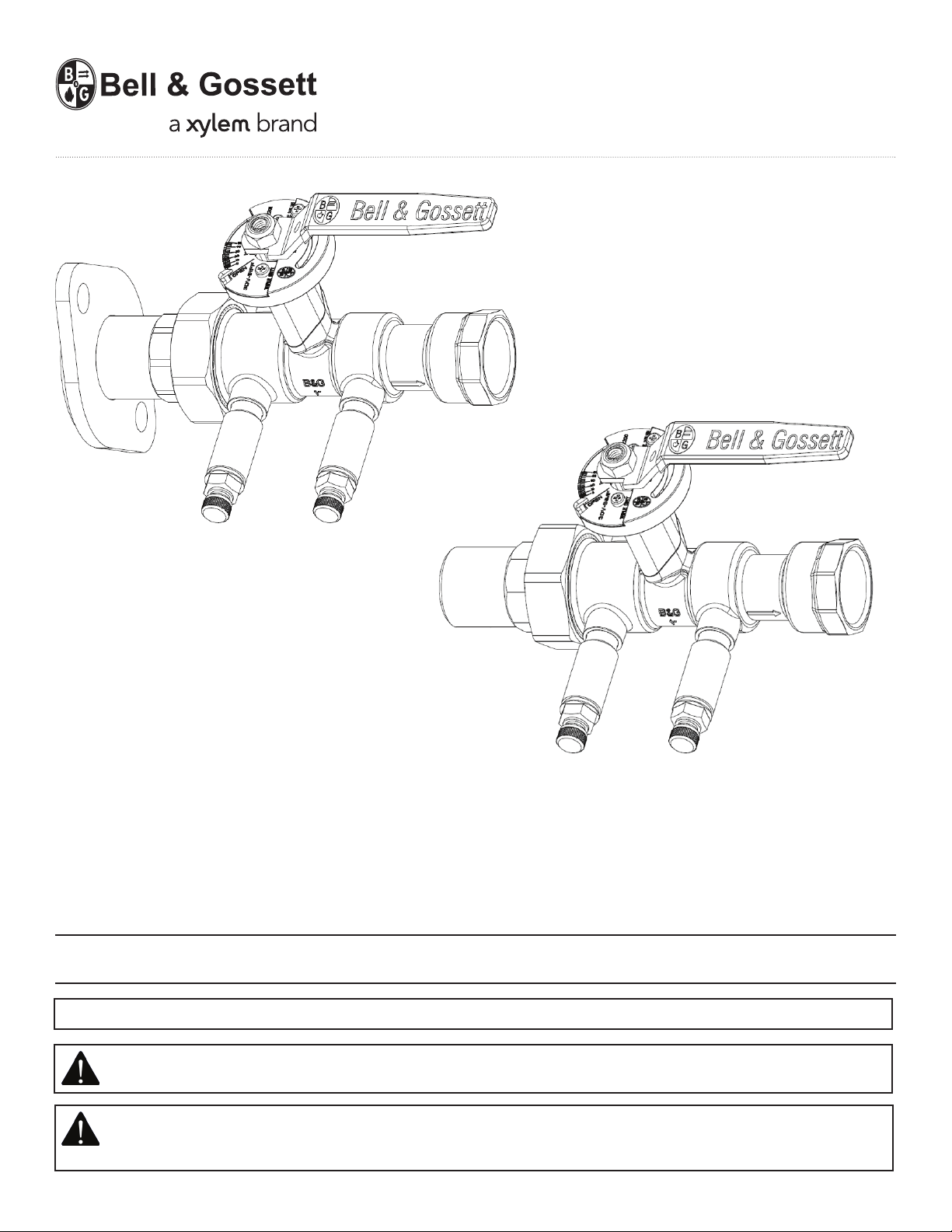
Rotatable Flange Tailpiece
Male NPT Tailpiece
Triple Duty Valve
Model 3DV Calibrated Balance Valves
INSTALLER: PLEASE LEAVE THIS MANUAL FOR THE OWNER’S USE.
NOTE: Bell & Gossett does not recommend Model 3DV Triple Duty Valve components to be used for potable water.
WARNING: This product may contain chemicals known to the State of California to cause cancer, or birth
defects or other reproductive harm.
SAFETY INSTRUCTION: This safety alert symbol will be used in this manual to draw attention to safety related
instructions. When used, the safety alert symbol means ATTENTION! BECOME ALERT! YOUR SAFETY IS
INVOLVED! FAILURE TO FOLLOW THE INSTRUCTIONS MAY RESULT IN A SAFETY HAZARD.
Page 2
A
B
Safety Message Level
Indication
DANGER:
WARNING:
CAUTION:
ELECTRICAL HAZARD:
NOTICE:
Operational Limits
Valve Temperature Max Working Pressure
Triple Duty Valve
NPT -4°F (-20°C) to 250°F (120°C) 200 PSI (1379 kPa)
A hazardous situation, which if not avoided, will result in death or serious injury.
A hazardous situation, which if not avoided, will result in death or serious injury.
A hazardous situation, which if not avoided, will result in major or minor injury.
The possibility of electrical risks if instructions are not followed in a proper
manor.
• A hazardous situation, which if not avoided, will result in an indescribable
result or state.
• A practice not related to personal injury.
Description
Bell & Gossett Model 3DV Triple Duty Valves are precision engineered valves used in heating and cooling systems which
perform all of the functions normally required on the discharge side of hydronic pump systems.
The valve serves as a non-slam check valve as needed for zoned pumping, parallel and standby pumping, and
condenser water applications. The spring-loaded internal check valve prevents valve chatter, and assures positive
shut-off.
Bell & Gossett’s Model 3DV Triple Duty Valve has a calibrated nameplate for general system balancing. It is also
equipped with P/T readout ports for more accurate system balance capabilities. The calibrated nameplate allows the
valve to be returned to the original balanced position after shut-off. Turning the valve to the closed position provides
positive shut-off.
Installation
Model 3DV Triple Duty Valves must be installed on the discharge side of the system or zone pump with the valve facing
the direction of flow as indicated by the arrow on the valve body.
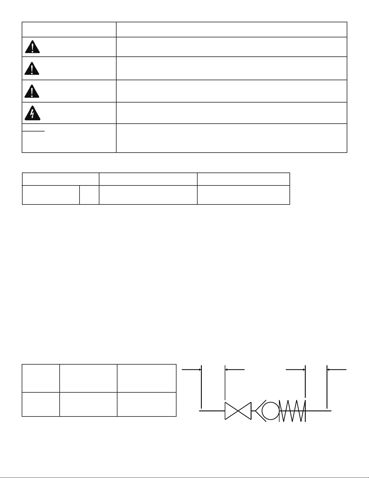
To retain calibrated accuracy, a minimum length of unrestricted straight pipe adjacent to the valve should be
maintained as follows:
Size
Upstream ”A”
(In pipe diameter)
Downstream ”B”
(In pipe diameter)
1/2” - 3” 5 2
Page 3
How to use Bell & Gossett model 3DV Triple Duty Valves for pre-set flow balancing
CAUTION: Hot un-insulated surfaces can cause burns to the skin. Do not touch hot surfaces. Failure to follow
these instructions could result in personal injury.
1. Identify the zone within a given circuit or circuit within a given system with the highest head loss.
2. Establish the value of the head loss in feet of water.
3. Establish the corresponding required GPM.
4. Select the appropriate size Triple Duty Valve (normally line size) for the required GPM.
5. Move the adjustment handle until the position indicator aligns with the OPEN position on the calibration plate.
6. Energize the zone, circuit and/or system pump(s) as applicable so that fluid is flowing through the Triple Duty Valve.
Make sure that all of the air has been directed to the compression tank (closed system) or vented to the atmosphere
(open system or closed system utilizing diaphragm or bladder tanks).
7. Using Bell & Gossett RP-250B readout probes, sequentially attach a Bell & Gossett differential pressure readout kit to
the readout valves (P/T ports) on the Triple Duty Valve.
WARNING: Hot water leakage can occur from readout valves (P/T ports) during probe insertion and during
hookup of readout kit. Follow the instruction manuals supplied with readout probes and readout kits for safe
use. Failure to follow these instructions could result in serious personal injury or death and property damage.
8. Read the differential pressure across the Triple Duty Valve.
9. Refer to the appropriate Triple Duty Valve performance curve in Performance Curve Booklet B-860B or Cv rating table
to determine flow based on the results from Step #4 and valve position indicator.
10. If the GPM does not agree with the specified (required) GPM, close the Triple Duty Valve accordingly. Repeat Steps
#4, #5, and #6 until the required results have been achieved.
11. Adjust pump flow so that circuits are receiving their design flow. This can be accomplished by adjusting the Triple
Duty Valve installed on the pump discharge or by changing the pump impeller size.
CAUTION: It is possible, depending on the age or condition of the stem seal, for some liquid to escape
during Triple Duty Valve adjustment. Do not have eyes or face on a level with the sides of the Triple Duty Valve.
Failure to follow this caution could result in serious personal injury.
NOTICE: If a high degree of throttling of flow at pump discharge is required, Bell & Gossett recommends that
the pump impeller be sized to produce design flow. This will reduce electrical energy consumption
NOTE: If the system contains a liquid with a specific gravity and/or viscosity higher or lower than that of water, apply
the appropriate correction factor noted in these instructions to obtain the actual GPM for the system liquid.
How to use Bell & Gossett model 3DV Triple Duty Valves as an isolation valve
1. Move the adjustment handle until the position indicator aligns with the CLOSED position on the calibration plate.
2. Close the isolation valve on the other side of the equipment to be serviced.
3. Drain the system between the Triple Duty Valve and the second isolation valve.
WARNING: Check for proper sealing when using as an isolation valve. If the seat is not sealing properly, liquid
will continue to flow from the valve. In this case, the Model 3DV Triple Duty Valve must be isolated from the
system and replaced. Failure to follow these instructions could result in serious personal injury or death and
property damage.
Page 4

How to use the memory stop feature
1. Make the final degree of closure setting.
2. Loosen the memory stop locking screw in the slot on the top of red knob.
3. Slide the memory stop screw in the slot clockwise until screw stops.
4.Tighten the memory stop screw.
Service Instructions
Periodically inspect the Model 3DV Triple Duty Valve for signs of leakage or corrosion.
WARNING: Corrosion or leakage are indications that the Model 3DV Triple Duty Valve must be replaced. Failure
to follow these instructions could result in serious personal injury or death and property damage.
The P/T readout ports and drain plugs found on Bell & Gossett Model 3DV Triple Duty Valves come pre-assembled with
a leading industrial thread sealant, Loctite 567, and are tightened to appropriate levels. With that in mind, the following information should help to clarify questions regarding the adjustment or servicing of those components when
required.
CAUTION: Installation and maintenance must be preformed by a qualified professional. Service should not
be preformed on any valve in an active Hydronic loop. Before attempting to make any required adjustments,
properly isolate and drain the branch loops that require service and allow the valves to reach a safe handling
temperature and zero pressure condition. Use proper safety equipment including gloves, goggles, or similar
tools to avoid contact with system fluids and common hazards. Failure to follow these instructions could result
in personal injury and property damage.
Any field adjustment of factory installed components will break the original thread seal and could cause leakage. This
will necessitate the removal, cleaning, and resealing of those parts per the instructions below.
Should any adjustment or servicing of P/T readout ports or drain plugs be required, please take the following steps:
1. Completely remove the desired component from the valve.
2. Taking care not to damage any threads on the component or the valve, clean off all of the old thread sealant. Use a
wire brush and gentle abrasion if necessary. Allow the valve and the component to dry.
Note: If the component or valve appears to have been damaged, replace it.
3. Starting with the second thread of the NPT male valve component, apply a 360° bead of Loctite 567 thread sealant/
lubricant as shown below. Follow Loctite handling precautions as noted on the product labeling.
4. If Loctite 567 is unavailable, we recommend RectorSeal No. 5 pipe thread sealant for all non-glycol based
applications, or any PTFE thread sealing tape. Be sure to follow the manufacturer specific handling precautions and
application instructions as noted on the product labeling.
5. Thread component into valve until it is finger tight.
6. Apply torque to the following specification:
Page 5

Loctite and Loctite 567 are registered trademarks of Henkel AG & Co. RectorSeal No. 5 is a registered trademark of
RectorSeal Corporation.
Component Torque
Size Type
1/4” NPT P/T Readout Port, Drain Plug
NOTICE: The use of thread sealants/lubricants on threads also provides lubricity. Over application of torque
may cause damage to the valve port or component.
7. Properly assembled valve components will immediately seal to moderate pressure (100 PSI or less). For maximum
pressure resistance, allow the Loctite 567 or Rector Seal No. 5 thread sealant to cure for 24 hours. PTFE tape typically
does not require curing to achieve maximum pressure resistance.
Insulation
Bell & Gossett recommends that insulation be attached to the Model 3DV Triple Duty Valve after the system has been
balanced and the completed V1000265 tag has been wired to the Triple Duty Valve.
NOTE: Tape or other acceptable means should be used to secure the insulation to the Model 3DV Triple Duty Valve.
9.0 ft.-lbs + 3.0 ft.-lbs. / -0
Page 6
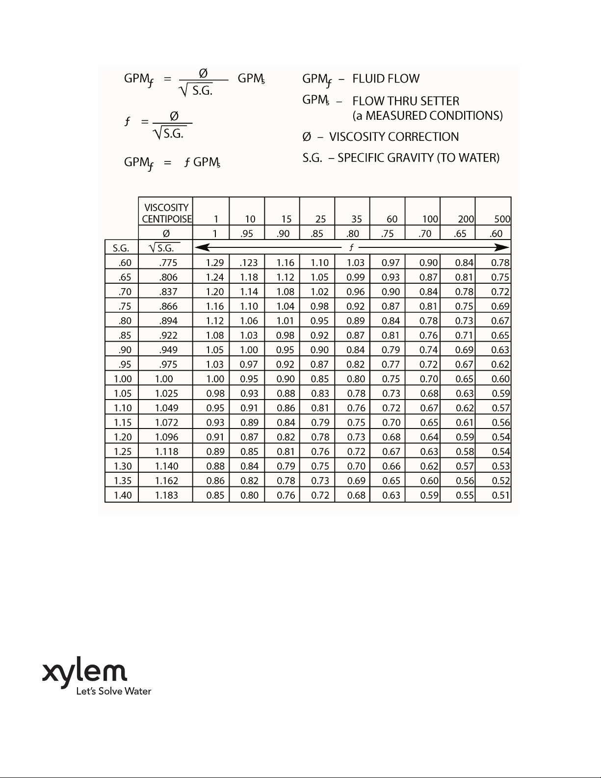
B&G Triple Duty Valve correction factors for viscosity and specific gravity
Xylem Inc.
8200 N. Austin Avenue
Morton Grove, Illinois 60053
Phone: (847) 966-3700
Fax: (847) 965-8379
www.xyleminc.com/brands/bellgossett
Bell & Gossett is a trademark of Xylem Inc. or one of its subsidiaries.
© 2012 Xylem Inc. V1000188B May 2012
 Loading...