

Page 1
INSTRUCTION MANUAL
V1000187C
1/2” to 3” NPT size
1/2” to 2” Sweat size
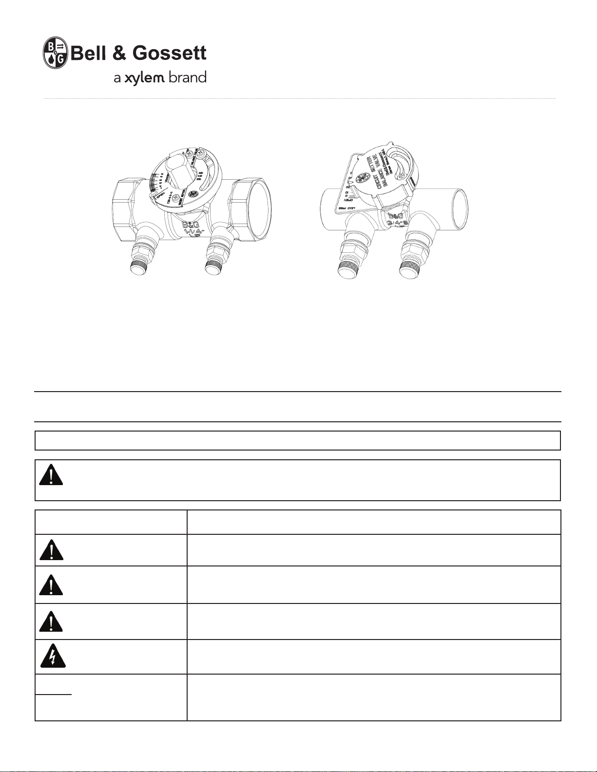
Circuit Setter® Plus Calibrated Balance Valves
CSA Certified: AB1953; Vermont S152; Maryland House Bill 372 (Statute 12-605)
NSF/ANSI-372
INSTALLER: PLEASE LEAVE THIS MANUAL FOR THE OWNER’S USE.
NOTE:
Bell & Gossett recommends Lead Free Brass or Stainless Steel Booster Pumps be used for pumping potable water.
SAFETY INSTRUCTION: This safety alert symbol will be used in this manual to draw attention to safety related
instructions. When used, the safety alert symbol means ATTENTION! BECOME ALERT! YOUR SAFETY IS
INVOLVED! FAILURE TO FOLLOW THE INSTRUCTIONS MAY RESULT IN A SAFETY HAZARD.
Safety Message Level
DANGER:
Indication
A hazardous situation, which if not avoided, will result in death or serious injury.
WARNING:
CAUTION:
ELECTRICAL HAZARD:
NOTICE:
A hazardous situation, which if not avoided, will result in death or serious injury.
A hazardous situation, which if not avoided, will result in major or minor injury.
The possibility of electrical risks if instructions are not followed in a proper
manor.
• A hazardous situation, which if not avoided, will result in an indescribable
result or state.
• A practice not related to personal injury.
Page 2
Operational Limits
Valve Temperature Max Working Pressure
Circuit Setter
Type Solder Maximum Limitations 1/2” - 1” Maximum Limitations 1-1/4” - 2”
95-5
Tin-Antimony
Description
Bell & Gossett Circuit Setter Plus Balance Valves are precision engineered valves used in heating and cooling systems
which function as precise system balancing valves and highly accurate variable orifice flow meters.
Installation Instructions
Circuit Setter Balance Valves are bi-directional valves and can be installed in most attitudes; however, they should be
installed in a position to facilitate the ease of balancing the system.
NPT and sweat style Circuit Setter Balance Valves are equipped with 1/4” NPT plugged drain port. If the drain port is to
be used to drain a riser on the downstream side of a terminal unit, it should be situated on the terminal unit side of the
riser when installing the Circuit Setter.
NPT -4°F (-20°C) to 250°F (120°C) 400 PSI (2758 kPa)
Sweat Based on Solder Type ASTM Std. B16.18
Pressure PSI (kPa) Temp °F (°C) Pressure PSI (kPa) Temp °F (°C)
300 (2069) 200 (93) 300 (2069) 175 (79)
250 (1724) 225 (107) 250 (1724) 200 (93)
200 (1379) 250 (121) 175 (1207) 250 (121)
NOTICE: Bell & Gossett Circuit Setter Balance Valves are not recommended for use with meter connections pointing
down. Dirt and debris will collect in the connections and foul up the readout valves and readout meters.
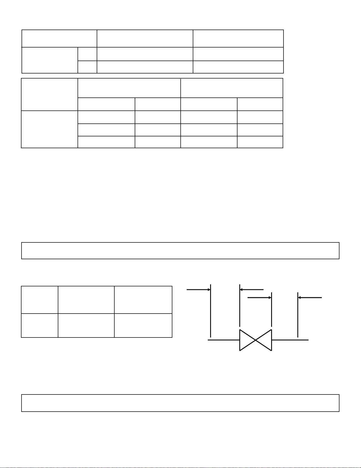
To retain calibrated accuracy, a minimum length of unrestricted straight pipe adjacent to the valve should be
maintained as follows:
A
Size
1/2” - 3” 3 1
When installing the Circuit Setter in a coil hook-up kit, the valve should be installed on the return side of the coil with
union end adapter on the upstream side and other end on the downstream side, except when used on the bypass line.
Be aware of water weight in the valve and connected piping when installing your system.
NOTICE: Never use the valve itself as a form of piping support. Please support valves and piping according to the local building code. Failure to follow these instructions may result in property damage.
Upstream ”A”
(In pipe diameter)
Downstream ”B”
(In pipe diameter)
B
Circuit Setter Balance Valves With Sweat Connections
1. Use a torch with a sharp pointed flame.
2. Clean tube ends and Circuit Setter connections thoroughly.
3. Use 95-5 (Tin-Antimony) solder and a good grade of flux.
Page 3

CAUTION:
Heat associated with the use of silver
not use silver solder. Failure to follow these
personal injury.
solder may damage a Circuit Setter voiding the
instructions could result in property damage and/or
warranty. Do
moderate
CAUTION:
Excessive use of solder in a vertical
not use excessive flux. Failure to follow these
installation may result in damage to the valve seat
instructions could result in property damage and/or
and ball. Do
moderate
personal injury.
4. When sweating the joints, first wrap the valve body with a
jecting the Circuit Setter to excessive heat. Allow the valve
RV-125A Readout Valves packaged with the Circuit Setter
CAUTION:
should be taken to prevent overtightening of
The use of PTFE impregnated pipe
compound and PTFE tape on threads provides
the readout valves which may damage the Circuit Setter.
5. Check soldered connections for leaks. If resoldering is
cool wet rag, then direct the flame with care to avoid sub-
body to cool below 200°F before installing the (2) Model
Balance Valve.
lubricity. Care
required, remove the readout valves before applying the
torch to the connection(s).
Circuit Setter Balance Valves With Connections
1. Apply pipe compound conservatively to male connecting
CAUTION:
The use of PTFE impregnated pipe
should be taken to prevent overtightening of
NPT
fittings only.
compound and PTFE tape on threads provides
lubricity. Care
the readout valves which may damage the Circuit Setter.
2. Check connections for leaks.
How to use Bell & Gossett Circuit Setter Balance Valves for pre-set flow balancing
All Circuit Setter balance valves within a common zone, circuit, or system, with a common pump, are brought into
balance with each other by establishing a common BALANCE GOVERNING HEAD LOSS as noted.
CAUTION: Hot un-insulated surfaces can cause burns to the skin. Do not touch hot surfaces. Failure to follow
these instructions could result in personal injury.
1. Identify the zone within a given circuit or circuit within a given system with the highest head loss.
2. Establish the value of the head loss in feet of water.
3. Establish the corresponding required GPM.
4. Select the appropriate size Circuit Setter balance valve (normally line size) for the required GPM.
5. Using Side #1 of the V91483 Circuit Setter Balance Valve Calculator, set the degree of closure hairline in the red
section of the Calculator over the 0° setting for the appropriate size Circuit Setter and read the head loss opposite the
required GPM. The setting for this Circuit Setter will remain 0°.
6. Add the head loss in Step #5 to the head loss in Step #2 to establish the Balancing Governing Head Loss for the
zone or circuit.
7. Subtract the required head loss for each zone circuit from the Balance Governing Head Loss in Step #6 to establish
the head loss difference for each zone or circuit which is to be brought into balance with Step #6.
8. The head loss difference in Step #7 and the required GPM in Step #3 are lined up in the white section of Side #1
of the Calculator and the degree of closure for the specific Circuit Setter balance valve is shown under the degree of
closure hairline in the red section of the Calculator for the appropriate size Circuit Setter.
9. Adjust the Circuit Setter by turning the red know by hand on sizes ½” thru 1” or by placing a wrench on the wrench
flats provided on sizes 1-1/4” thru 3” to set the position determined by the preceding procedure.
CAUTION: It is possible, depending on the age or condition of the stem seal, for some liquid to escape during
Circuit Setter adjustment. Do not have eyes or face on a level with the sides of the Circuit Setter. Failure to
follow this caution could result in serious personal injury.
Notes:
• Head Loss in Steps #6 and #2 are a fixed head requirement the zone, circuit, or system pump, as required must
overcome.
• Refer to the G95872 pre wired tag packaged with the Circuit Setter balance valve and fill in the appropriate
information. Attach the tag to the Circuit Setter for future reference.
Page 4

How to use Bell & Gossett Circuit Setters to proportionally Balance a system
1. Open fully all Circuit Setters on a single pump system.
2. If more than one branch circuit is used, start the balance procedure by reading all of the flows to the units in a
branch. Each unit (coil) should have its own Circuit Setter for flow balancing. Using Bell & Gossett RP-250B readout
probes, sequentially attach a Bell & Gossett differential pressure readout kit to the readout valves (P/T ports) on each
Circuit Setter balance valve.
WARNING: Hot water leakage can occur from readout valves (P/T ports) during probe insertion and during
hookup of readout kit. Follow the instruction manuals supplied with readout probes and readout kits for safe
use. Failure to follow these instructions could result in serious personal injury or death and property damage.
3. Using Side #2 of the Bell & Gossett Circuit Setter Balance Valve Calculator (V91483), with the top hairline set on zero
for the size Circuit Setter being read, read the flow corresponding to the pressure drop read with the readout kit.
4. Calculate the ratio of the actual flow to the design flow for each unit in the branch. This is the proportional flow
rate. (Actual flow divided by design flow).
5. Select the Circuit Setter with the lowest proportional flow rater. This Circuit Setter is left in the full open position.
Every other Circuit Setter in the branch is then reset to the same proportional flow rate.
6. If there are additional branches, repeat the Steps #3, #4, and #5 above for each branch.
7. After all branches have been proportionally balanced, measure the full open flows on the Circuit Setters installed on
the risers. Calculate the proportional ratio of each riser Circuit Setter and select the one with the lowest proportional
ratio. This Circuit Setter is left fully open and the other riser Circuit Setters are adjusted to this same ratio as described
in Step #5 above.
8. Adjust pump flow so that circuits are receiving their design flow. This can be accomplished by adjusting a Circuit
Setter balance valve installed on the pump discharge or by changing the pump impeller size.
NOTICE: If a high degree of throttling of flow at pump discharge is required, Bell & Gossett recommends
that the pump impeller be sized to produce design flow. This will reduce electrical energy consumption.
How to use Bell & Gossett Circuit Setter Balance Valves as flow meters
1. Energize the zone, circuit, and/or system pump(s) as applicable.
2. Using Bell & Gossett Model RP-250B Readout Probes, sequentially attach a Bell & Gossett differential pressure read
out kit to the readout valves on each Circuit Setter Balance Valve.
WARNING: Hot water leakage can occur from readout valves (P/T ports) during probe insertion and during
hookup of readout kit. Follow the instruction manuals supplied with readout probes and readout kits for safe
use. Failure to follow these instructions could result in serious personal injury or death and property damage.
3. Read the differential pressure across the orifice of the Circuit Setter balance valve.
4. Using Side #2 of the Circuit Setter Balance Valve Calculator (V91483), set the hairline over the degree of closure as
indicated by the part of the red plastic knob or indicator plate parallel to the degree of closure noted on the calibration
plate, and read actual GPM flowing through the Circuit Setter opposite the gauge reading head loss noted in the white
section of Side #2.
NOTE: If the system contains a liquid with a specific gravity and/or viscosity higher or lower than that of water, apply
the appropriate correction factor noted in these instructions to obtain the actual GPM for the system liquid.
How to use Bell & Gossett Circuit Setter Balance Valves as an isolation valve
1. Move the adjustment knob or stem until the position indicator aligns with the closed position on the calibration
plate.
2. Close the isolation valve on the other side of the equipment to be serviced.
3. Open the drain valve to drain the system between the Circuit Setter and the second isolation valve.
WARNING: Check for proper sealing when using as an isolation valve. If the seat is not sealing properly, liquid
will continue to flow from the drain valves. In this case, the Circuit Setter must be isolated from the system
and replaced. Failure to follow these instructions could result in serious personal injury or death and property
damage.
How to use the memory stop feature
1. Make the final degree of closure setting.
2. Loosen the memory stop locking screw in the slot on the top of red knob.
3. Slide the memory stop screw in the slot (counter-clockwise for ½” thru 1” sizes and clockwise for 1-1/4” thru 3”
sizes) until screw stops.
4. Tighten the memory stop screw.
Page 5

Service Instructions
Periodically inspect the Circuit Setter for signs of leakage or corrosion.
WARNING: Corrosion or leakage are indications that the Circuit Setter must be replaced. Failure to follow
these instructions could result in serious personal injury or death and property damage.
The P/T readout ports and drain plugs found on Bell & Gossett Circuit Setter Plus calibrated balance valves come
pre-assembled with a leading industrial thread sealant, Loctite 567, and are tightened to appropriate levels. P/T readout
ports on Sweat model Circuit Setters are shipped loose and will need to be installed as per the instructions below. With
that in mind, the following information should help to clarify questions regarding the adjustment or servicing of those
components when required.
WARNING: Installation and maintenance must be performed by a qualified professional. Service should not be
performed on any valve in an active Hydronic loop. Before attempting to make any required adjustments,
properly isolate and drain the branch loops that require service and allow the valves to reach a safe handling
temperature and zero pressure condition. Use proper safety equipment including gloves, goggles, or similar
tools to avoid contact with system fluids and common hazards. Failure to follow these instructions could result
in personal injury and property damage.
Any field adjustment of factory installed components will break the original thread seal and could cause leakage. This
will necessitate the removal, cleaning, and resealing of those parts per the instructions below.
Should any adjustment or servicing of P/T readout ports or drain plugs be required, please take the following steps:
1. Completely remove the desired component from the valve.
2. Taking care not to damage any threads on the component or the valve, clean off all of the old thread sealant. Use
a wire brush and gentle abrasion if necessary. Allow the valve and the component to dry. Note: If the component or
valve appears to have been damaged, replace it.
3. Starting with the second thread of the NPT male valve component, apply a 360° bead of Loctite 567 thread sealant/
lubricant as shown below. Follow Loctite handling precautions as noted on the product labeling.
4. If Loctite 567 is unavailable, we recommend Rector Seal No. 5 pipe thread sealant for all non-glycol based
applications, or any PTFE thread sealing tape. Be sure to follow the manufacturer specific handling precautions and
application instructions as noted on the product labeling.
5. Thread component into valve until it is finger tight.
6. Apply torque to the following specification:
Component Torque
Size Type
1/4” NPT P/T Readout Port, Drain Plug
NOTICE: The use of thread sealants/lubricants on threads also provides lubricity. Over application of torque
may cause damage to the valve port or component.
9.0 ft.-lbs + 3.0 ft.-lbs. / -0
Page 6

7. Properly assembled valve components will immediately seal to moderate pressure (100 PSI or less). For maximum
pressure resistance, allow the Loctite 567 or Rector Seal No. 5 thread sealant to cure for 24 hours. PTFE tape typically
does not require curing to achieve maximum pressure resistance.
Loctite and Loctite 567 are registered trademarks of Henkel AG & Co. RectorSeal No. 5 is a registered trademark of
RectorSeal Corporation.
Insulation
Bell & Gossett recommends that insulation be attached to the Circuit Setter after the system has been balanced and the
completed G95872 tag has been wired to the Circuit Setter.
NOTE: Tape or other acceptable means should be used to secure the insulation to the Circuit Setter balance valve.
B&G Circuit Setter correction factors for viscosity and specific gravity
Xylem Inc.
8200 N. Austin Avenue
Morton Grove, Illinois 60053
Phone: (847) 966-3700
Fax: (847) 965-8379
www.xyleminc.com/brands/bellgossett
Bell & Gossett is a trademark of Xylem Inc. or one of its subsidiaries.
Bell & Gossett is a trademark of Xylem Inc. or one of its subsidiaries.
© 2013 Xylem Inc. V1000187C July 2013
 Loading...