

Page 1
BELL & GOSSETT
INSTRUCTION MANUAL
*
*
*
ThermoMate
*
®
* WARNING: Label Part No. V56871
must be installed in this location.
If missing, must be replaced.
Thermostatic Control Valves
Installation, Operation and Service Instructions
V02300
Revision D
INSTALLER: PLEASE LEAVE THIS MANUAL FOR THE OWNER’S USE.
DESCRIPTION
ThermoMate Thermostatic Control Valves are silent, efficient,
energy saving non-electric control valves that provide reliable
temperature control for hydronic and low pressure steam terminal units. The temperature range of ThermoMate Control Valves
is adjustable between 46°F (7.8°C) and 79°F (26.1°C). A drop in
room temperature causes the operator to open the valve.
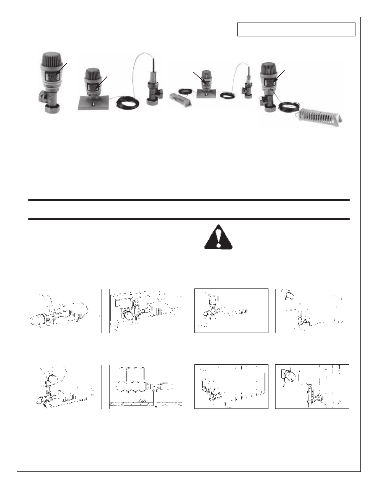
FIG. A
Baseboard radiation with Model TM42 angle pattern
valve body and Model TM51 self-contained thermostatic operator. (Thermostatic operator mounted thru
the side panel of the terminal unit cover.)
FIG. B
Baseboard radiation with Model TM12 angle pattern
valve body and Model TM51 self-contained thermostatic operator attached to the TM91 remote mounting base a nd sen sing element. (Remote mounting
base and operator mounted thru the front panel of the
terminal unit cover.)
SAFETY
INSTRUCTION
This safety alert symbol will be used in this manual to draw
attention to safety related instructions. When used, the safety
alert symbol means ATTENTION! BECOME ALERT! YOUR
SAFETY IS INVOLVED! FAILURE TO FOLLOW THESE INSTRUCTIONS MAY RESULT IN A SAFETY HAZARD.
Convector with Model TM21 straight pattern valve
body and Model TM61 thermostatic operator with
remote sensing bulb. (Mounted inside the terminal
unit cover.) Solder adaptor not furnished with valve.
D .GIFC .GIF
Convector with Model TM12 angle pattern valve body
and Model TM51 self-contained thermostatic operator
attached to the TM91 remote mounting base and
sensing element. (Remote mounting base and operator mounted on the wall outside of the terminal unit.)
FIG. E
Convertor with Model TM21 st raight pattern valve
body and Model TM61 t hermostatic operator with
remote sensing bulb attached to the TM91 remote
mounting base. (Remote mounting base and the operator mounted thru the front panel of the terminal unit
cover.)
© COPYRIGHT 1981, 1995
FIG. F
Free standing radiator with Model TM42 angle pattern
valve body and Model TM51 self-contained thermostatic
operator mounted on the radiator.
Free standing radiator with Model TM12 angle pattern
valve body and Model TM61 thermostatic operator
with remote sensing bulb mounted on the wall alongside of the terminal unit.
FIG. HFIG. G
Free standing radiator with Model TM12 angle pattern
valve body and Model TM61 thermostatic operator
with r emote sensing bulb attached to the TM91
remote mounting base. (Remote mounting base and
the operator are mounted on the wall alongside of the
unit.)
Bell & Gossett
Morton Grove, IL, U.S.A.
Page 2
MAXIMUM OPERATING LIMITATIONS
Temperature: 250°F (121°C)
Steam Pressure: 15 PSI (103.43 kPa)
Working Pressure: 200 PSI (1,379 kPa)
Differential Pressure:
1
/2" Valves 25 PSI (172.38 kPa)
3
/4" Valves 20 PSI (137.90 kPa)
1" Valves 15 PSI (103.43 kPa)
5. As shown in Figures C and G, the TM61 remote sensing
bulb may be installed inside the terminal unit below the
radiation or on a wall. Remove the plastic housing protecting the remote sensing bulb by pulling gently on the housing while holding the mounting base. Carefully remove the
sensing bulb from the mounting base and mount the base
to a wall or terminal unit. Replace sensing bulb and cover.
Coil excess capillary tubing and protect it from damage.
INSTALLATION INSTRUCTIONS
1. Fig. A through Fig. H shows the various ways the ThermoMate may be installed. Install the ThermoMate valve body
by attaching each end to the mating NPT pipe thread using
a pipe joint compound and tighten with a wrench. If a
sweat connection is used, outlet union connection should
be sweated to the terminal unit before union nut is connected to the ThermoMate.
CAUTION: The generous use of pipe joint com-
pound will foul the operating mechanism and prevent the ThermoMate from functioning properly. When
piping ThermoMate valve bodies to the system, apply
pipe compound to male threads only. Failure to follow
this instruction could result in property damage and/or
moderate personal injury.
CAUTION: The heat from supply piping of terminal
unit, solar heat or drafts from windows can cause the
temperature sensing element of the TM51 or TM61 to misinterpret the need for heat. If the TM51 operator is to be
used, it must be installed so that it is in a horizontal position or is protected from convection currents rising up the
supply pipe. Failure to follow this instruction could result in
property damage and/or moderate personal injury.
CAUTION: Overtightening and breakage can be
caused by the use of Teflon impregnated pipe compound or Teflon tape on pipe threads. Use caution when
tightening pipe joints with Teflon materials applied.
Failure to follow these instructions could result in property damage and/or moderate personal injury.
2. If heat is not immediately required from the terminal unit,
and the valve operator is to be installed at a later date,
leave the red plastic protective cap tightly assembled to
the valve to isolate the terminal unit and protect the operating mechanism. However, temporary heating can be provided by loosening the protective cap which allows the
ThermoMate Valve to Stay Open.
3. The TM51 or TM61 operators are installed as follows: Remove the red plastic protective cap from the valve body.
While pushing the operator down on the brass hex packing
nut, rotate it until mating slots in the operator engage the
hex nut. Secure the union nut onto the ThermoMate valve
body while continuing to push down on the operator. The
installation of the operator is simplified by setting the operator to the #6 temperature setting.
4. As shown in Figure B and D, the TM91 remote mounting
base and sensing element can be mounted either on the
terminal unit cover or a wall. Use the remote sensing element as a template to mark the location of mounting holes.
If mounted on a terminal unit, drill a 1
centered between the two mounting holes. This will allow
the operator to pass through and be mounted on the valve
body. Coil the excess capillary tube and secure so that it
does not get damaged.
5
/16" diameter hole
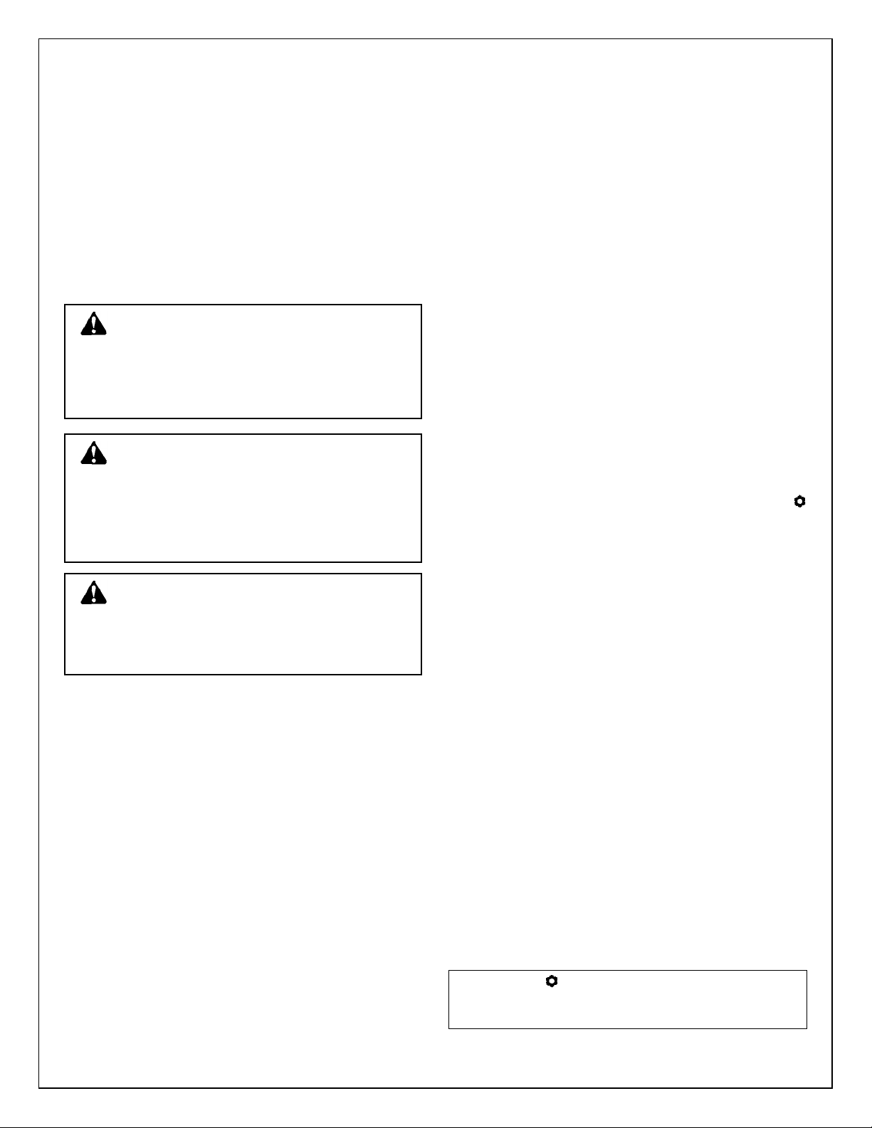
OPERATING INSTRUCTIONS
1. The room temperature can be changed by rotating the cap
(Fig. J) on the operator until the desired number on the cap
lines up with the index pointer in the bezel window. The
number on the operator cap correspond to temperature
settings as shown in fig. H.
2. Using memory feature (day/night temperature)
a) Turn cap to desired day temperature number setting.
Example: Set pointer to #4 for 68°F or 20°C daytime
temperature.
b) Pull the night set back ring up off of the bezel.
c) You will note that the night set back ring has a sun sym-
bol and a moon symbol. The sun symbol indicates the
daytime temperature setting and the moon the night
time setting. The night time setting will be 5.4°F (3°C)
lower than the daytime temperature. Replace the night
set back ring so that the sun symbol lines up with the
pointer on the bezel. For night time setting, rotate the
cap so that the moon symbol lines up with the pointer.
3. Limiting the maximum set temperature
a) Rotate the cap so that the indicator points to the
position.
b) Pull the shroud down from the bezel.
c) Note that numbers are molded into the bezel diameter
which is covered by the shroud. These numbers from 10
to 28 correspond to maximum temperature in °C. Fig. I
shows this relationship in °F. Beneath these numbers
are slots that correspond to the numbers. The lock and
range lever is inserted into one of the slots. To change
the maximum temperature set point pull the locks range
lever out of its slot and insert into the new maximum
temperature slot.
d) Reassemble the shroud to the bezel. The small notch on
the shroud must be on the opposite side of the bezel cut
out indicator where the setting is displayed. Another way
to line up the shroud to reassemble it to the bezel is to
line up the notch in the shroud with the long slot in the
bottom of the bezel which is just past the number 28.
4. Locking set temperatures
a) Set the desired temperature at the pointer in the bezel
window. For example, a setting of 4 is equal to 68°F
(20°C). Refer to Fig. H for other settings.
b) Slide the shroud down off the operator which will reveal
numbers molded into the bezel which was covered by
the shroud. To lock the set temperatures to 68°F (20°C)
put lock and range levers in slots 20 and 22. Refer to
Fig. K for other settings.
c) Reinstall the shroud by lining up the notch in the shroud
with the long slot in the bottom of the bezel which is just
past the number 28.
0 123456
Approx. 0 8 11 14 17 20 23 28 °C
32 46 52 57 63 68 73 79 °F
FIG. H
2
Page 3

Max Temp. °C
(Adj 10 11 12 13 14 15 16 17 18 19 20 21 22 23 24 25 26 27 28
Setting)
Max Temp. °F
46 48 50 52 53.6 55.3 57 59 61 63 64.6 66.3 68 69.6 71.3 73 75 77 79
Min. Temp °F
46 48 46 46 46 46 46 46 46 46 46 46 46 46 46 46 46 46 46
FIG. I
123456
11, 13 14, 16 17, 19 20, 22 23, 25 26, 28
FIG. K
ADJUSTMENT RANGE
b) Remove the bonnet and gland assembly by turning the
chrome plated bonnet hex nut in a counterclockwise
direction.
c) Inspect the valve seat and remove any foriegn material
that might prevent the ThermoMate from providing positive shut off. If the valve seat is corroded, the valve
body must be replaced.
d) Install the new bonnet and gland assembly and tighten
securely.
e) Return system to normal operation.
f) Inspect the bonnet and gland assembly for leaks and
tighten additionally if necessary.
g) Reassemble the ThermoMate operator to the valve
body by pushing it down on the brass hex gland and
rotating the operator until you feel the slots in the actu-
ator engage the gland nut. While continuing to push
down, engage and tighten the knurled union nut to
the valve body. It is helpful if the operator is set to the
highest temperature.
2. Replacement of Gland Assembly
a) If the gland assembly is leaking it can be replaced while
the ThermoMate is still pressurized if the valve disc is in
good condition and is backseating properly.
b) Remove the valve operator as in 1(a) above.
WARNING: Hot system fluid can be hazardous.
Allow the system to cool to 100°F (37.8°C) or below
before removing the gland assembly. Failure to follow this
instruction could result in serious personal injury or death
and property damage.
FIG. J
SERVICE INSTRUCTIONS
WARNING: Leakage or corrosion of ThermoMate
are signs of an impending serious failure of the
ThermoMate. Periodically inspect the ThermoMate for
signs of leakage or corrosion. If noted, the failed part or
assembly must be replaced. Failure to follow this instruction could result in serious personal injury or death and
property damage.
1. Replacement of Bonnet and Gland Assembly
WARNING: Hot system fluid can be hazardous.
Allow the system temperature to cool to 100°F
(37.8°C) or below before attempting any service. Isolate
the ThermoMate from the system or drain system. If system is not drained, relieve pressure from the ThermoMate.
Leave drain open during servicing. If servicing a steam
system, make sure that all electrical power is disconnected.
Failure to follow this instruction could result in property
damage and/or moderate personal injury.
a) Remove the valve operator by pushing down on the
operator and turning the knurled union nut counterclockwise.
c) Slowly loosen the brass hex gland nut and check for
leakage.
WARNING: If fluid escapes it is a sign that the valve
disc is not backseating properly and a hazardous
condition exists. If leakage is found, STOP. Isolate the
ThermoMate or drain the system before proceeding.
Failure to follow this instruction could result in serious
personal injury or death and property damage.
d) Finish removing the gland assembly.
e) Inspect the bonnet assembly for signs of damage or
corrosion. Replace the bonnet assembly as noted in 1 if
damage is found.
f) Install the new gland assembly and tighten securely.
g) Return the system to normal operation.
h) Check the gland assembly for leakage. Tighten addi-
tionally if necessary.
i) Replace the operator as in 1(g) above.
3. Replacement of Operator
a) Move the operator to the highest temperature setting.
Push down on the operator and unscrew the knurled
union nut (counterclockwise) that attaches the operator
to the valve body.
b) Examine the valve stem and gland assembly for signs of
leakage, if foun replace the gland assembly.
c) Install the new operator by pushing operator down on
the brass hex gland nut while slowly rotating the opera-
tor until you feel the slots in the operator engage the
hex of the gland nut. While continuing to push down,
engage and tighten the knurled nut to the valve body.
d) Set the operator to the desired temperature setting.
3
Page 4

INSTALLATION INSTRUCTIONS
FOR TAMPER PROOF COVER (See Fig. L)
1. Remove the night set back ring and the shroud from the
operator. The set back ring is removed by pulling it up and
the shroud is removed by pulling it down. To remove the
shroud operator must be removed from the valve body.
2. Mount the operator on the valve body and set to desired
temperature. If it is desired to lock the set temperature
refer to Section 4 under operating instructions.
3. Place the tamper proof cover over the operator so that the
window lines up with the temperature scale.
4. Place the tamper proof cover retaining collar halves over
the valve body, operator nut and tamper proof cover lip.
Notch in retaining collar must be fitted over lug on valve
body.
5. Hold the two halves of the retaining collar together and
lock in place with two supplied screws. Two sets of screws
are supplied. A standard set of machine screws and a set
of screws which require drilling out to remove if you want
to make it more difficult to remove tamper proof cover.
OPERATING INSTRUCTIONS
WITH TAMPER PROOF COVER
Once tamper proof cover is installed changes in temperature
setting can only be made by removing cover.
SERVICE INSTRUCTIONS
WITH TAMPER PROOF COVER
1. The tamper proof cover can be removed to service the
valve or the operator by removing the two screws holding
the two halves of the retaining collar together and then
removing the cover by pulling it up. If the permanent type
screws were used, they will have to be drilled out to remove
the retaining collar.
2. To complete the servicing of the ThermoMate refer to the
service instructions elsewhere in this manual.
TAMPER PROOF COVER
RETAINING
COLLAR
NIGHT
SET BACK
RING
SHROUD
SCREW
VALVE BOOT
NOTCH
FIG. L
PRINTED IN U.S.A. 8-95
For further information, contact Bell & Gossett, 8200 N. Austin Avenue, Morton Grove, IL 60053,
Phone (847) 966-3700 – Facsimile (847) 966-9052.
Bell & Gossett
Morton Grove, IL, U.S.A.
 Loading...