

Page 1
®
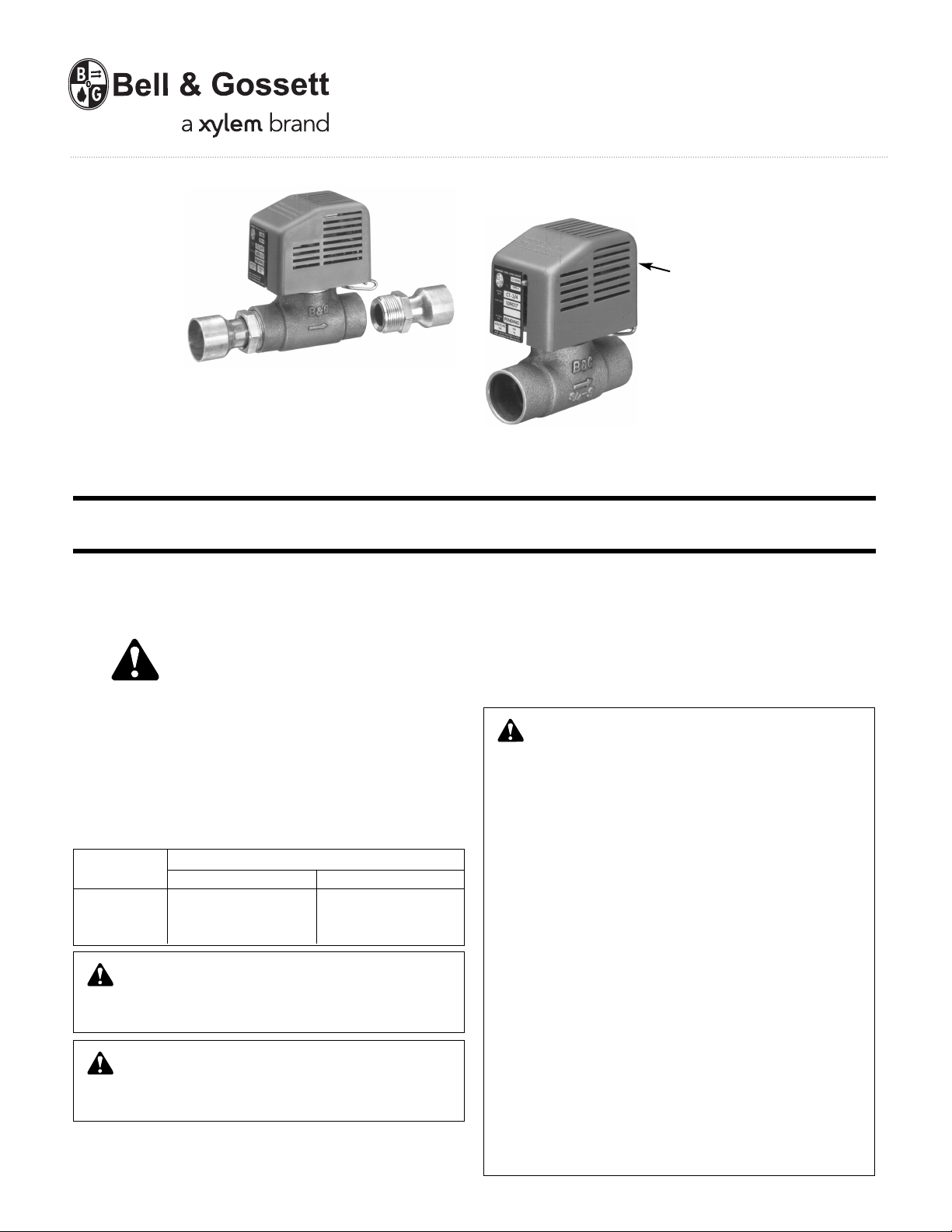
Comfort-Trol
PATENT NO’S. 4,553,733 AND 4,560,140
Zone Control Valve
INSTALLER: PLEASE LEAVE THIS MANUAL FOR THE OWNER’S USE.
INSTRUCTION MANUAL
V01348H
WARNING LABEL PART NO. V56871
INSTALLED IN THIS LOCATION.
IF MISSING IT MUST BE REPLACED.
DESCRIPTION
A two wire heat motor operated valve designed for Hydronic Heating/
Cooling Systems.
SAFETY
INSTRUCTION
This safety alert symbol will be used in this manual to draw attention
to safety related instructions. When used, the safety alert symbol
means ATTENTION! BECOME ALERT! YOUR SAFETY IS INVOLVED!
FAILURE TO FOL LOW T HE INST RUCTION S MAY RESU LT IN A
SAFETY HAZARD.
PERFORMANCE CHARACTERISTICS:
Maximum differential shut off pressure: 35 PSIG
WORKING PRESSURE & TEMPERATURE LIMITS
(SOLDER TYPE LIMITS FOR ASTM STD. B16.18)
TYPE OF
SOLDER PRESSURE PSI TEMPERATURE °F
95-5
TIN- 125 240
ANTIMONY
CAUTION: Heat associated with the use of silver solder will
damage the Comfort-Trol and void the product warranty.
Use only the low temperature solder specified. Failure to follow
these instructions could result in property damage and/or moderate personal injury.
WARNING: Solder joints will fail if used at pressures or tem-
peratures above those listed in the above table. Do not
exceed the temperature and pressure limitations. Failure to follow
the above instruction can cause the joint to fail resulting in serious
personal injury and/or property damage.
Maximum ambient temperature: 125°F.
Electrical rating: 24 Volt 50/60 Cycle, 1Ø, 15VA AC
MAXIMUM LIMITATIONS
THERMOSTAT
24 Volt two wire with 0.6 ampere heat anticipator setting.
TRANSFORMER
115/24 volt rated at 40 VA for a maximum of three Comfort-Trol Zone
Valves. Note: This transformer must be dedicated to the Comfort-Trol
Zone Valves and not be used to power any other device.
WARNING: Hazardous conditions could occur if the following notes are not adhered to:
READ PRIOR TO INSTALLING COMFORT-TROL
1. Do not install Comfort-Trol in a dusty area or in an area where
the flow of air to the operator is restricted because erratic
operation or premature failure may occur.
2. Use 95-5 (Tin-Antimony) solder and a good grad of flux to
solder the Comfort-Trol valve body into the system.
NOTE: a. Remove the brass bonnet and retainer assembly
3. Do not install a jumper wire between terminals #1 and #2
because the thermostat heat anticipator may burn out when
the Comfort-Trol operator is energized.
4. Keep external wiring from contacting the Comfort-Trol operator
cover by securing the wiring to a nearby support.
5. Use only silicone grease to lubricate the valve gland pin and
O-ring seals. Do not use lubricants with a petroleum base. The
use of a petroleum base lubricant will cause swelling and failure of U-rings.
6. Do not insulate the Comfort-Trol Zone Valve Operator.
7. Use of additives to the system may be harmful to the Comfort-Trol.
Failure to follow these instructions could result in serious personal
injury or death and property damage.
from the valve body before applying heat to the
body. Failure to do so will damage the valve seals
and discs.
b. Excessive use of solder in a vertical installation may
result in damage to the valve seat.
c. Avoid excessive use of flux.
d. Heat associated with the use of silver solder may
damage the Comfort-Trol.
WARNING NOTES:
Page 2
INSTALLATION INSTRUCTIONS
The B&G Comfort-Trol Zone Valve can be installed horizontally or vertically. However, the following precautions should be taken: When
installing the valve in a vertical position, the electrical connections
must be at the top of the operator. On chilled water applications the
operat or should be above the pipe cen terline . If the valv es are
installed near the boiler, locate them a sufficient distance from the
breeching so they are not affected by flue temperatures.
4. Check solder connections for leaks. If resoldering is neede d,
remove the bonnet assembly and resolder.
5. Assemble the Comfort-Trol operator onto the valve body (the operator can be rotated 360° after it is installed) by pushing down on
the operator until the wire retainers into the operator frame (Fig. 3,
Item E) snap into the retaining groove on the brass bonnet (Fig. 3,
Item C).
6. Electrically wire the Comfort-Trol to the system as described in one
of the following wiring diagrams.
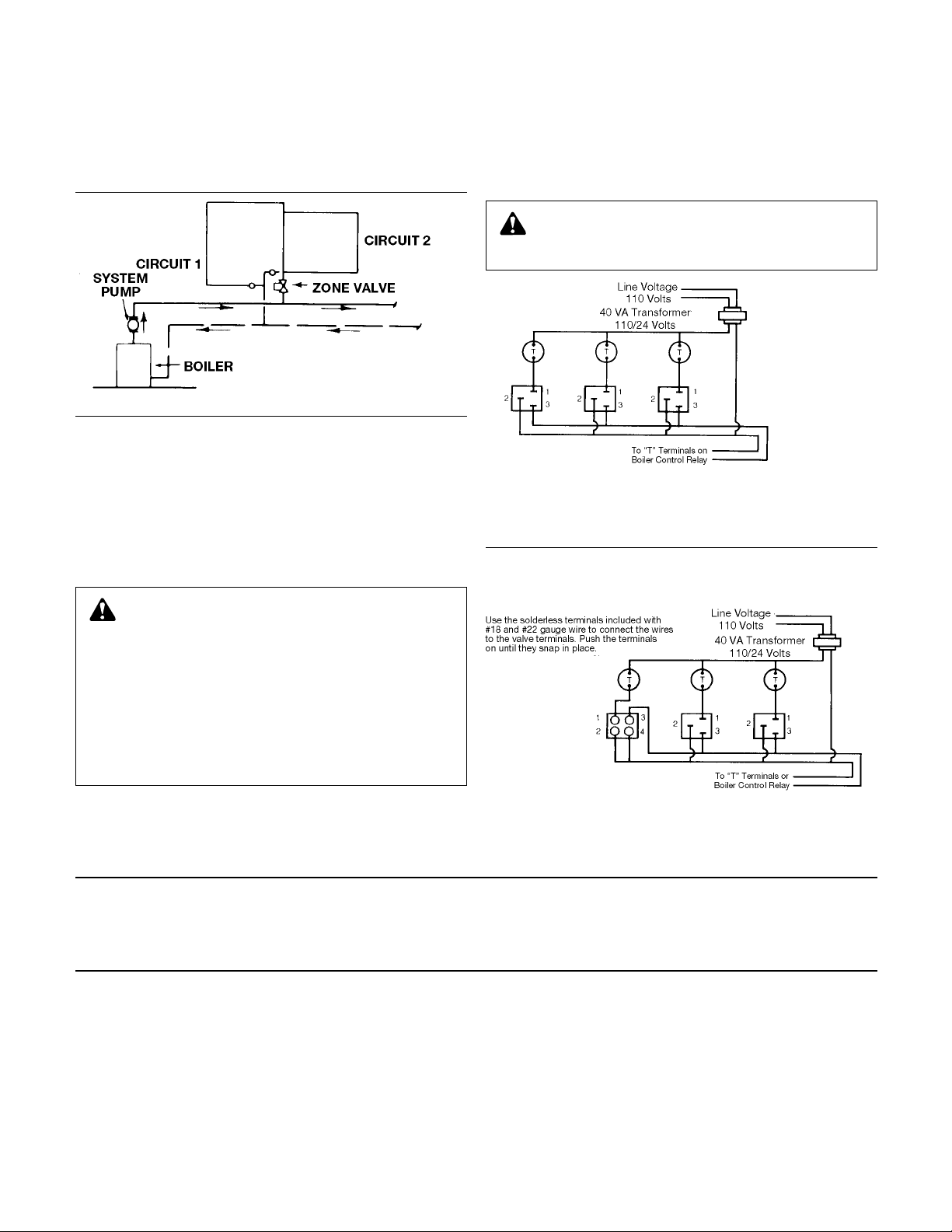
FIG. 1
ote: When two circuits are used in a
N
single zone, always join the circuits to
a common return as shown in Figure 1.
There can be no flow in circuit 1 or 2
hen the zone valve is closed.
w
1. Remove the brass bonnet and retainer assembly from the valve
body as shown in Figure 3.
NOTE: Model w it h flare connect or s can be left ass em bled if
Comfort-Trol is removed from piping before soldering connectors
in place.
2. Solder the valve body into position with the arrow on the body
pointing downstream.
a. Clean the tube ends and Comfort-Trol valve body connections
thoroughly.
b. Use 95-5 (Tin-Antimony) solder, a good grade of flux and a torch
with a sharp pointed flame.
WARNING: Damage to Comfort-Trol body or bonnet may
occur from improper installation, which can cause leakage
or failure of Comfort-Trol.
a. Avoid excessive use of flux and solder when installing Comfort-
Trol in a vertical position because damage to the valve seat
may occur.
b. When soldering the joints, direct the flame with care to avoid
subjecting the valve body to excessive heat.
c. Allow the valve body to cool below 100°F before installing the
bonnet and retainer assembly.
Failure to follow these instruction could result in serious personal
injury or death and property damage.
3. Insert the bonnet assembly with retainer into the valve body and
secure with the two retaining screws. Be careful not to damage the
O-ring seal when inserting the bonnet assembly (Fig. 3, Item A). If a
lubricant is required, apply silicone grease to the bonnet assembly
below the retainer. Do not use lubricants with a petroleum base.
CAUTION: Transformer overload. Do not wire more than
three Comfort-Trol or Modumate Zone Control Valves to
one 40 VA Transformer. Failure to follow these instructions could
result in property damage and/or moderate personal injury.
ote: This transformer
N
ust be dedicated to
m
omfort-Trol use only.
C
No other controls are
to be powered from it.
Improper operation of
omfort-Trol will result.
C
ote: Terminal 3 is not
N
sed if a continuously
u
perating pump is used.
o
FIGURE 2A
1, 2 OR 3 COMFORT-TROLS – SINGLE TRANSFORMER
INTERMITTENT PUMP OPERATION
IMPORTANT: Figure 2B is correct
only when the ModuMate was wired
per factory recommendations.
Note: Terminal 3 is not
used if a continuously
operating pump is used.
See Transformer
Note in Fig. 2A
FIGURE 2B
COMFORT-TROL AND MODUMATE WIRED
TO THE SAME TRANSFORMER
INTERMITTENT PUMP OPERATION
OPERATING INSTRUCTIONS
The Com fo rt-Trol is opened by a heat motor, therefore, the re is
approximately a two minute period between the time the thermostat
closes, calling for heat, and the time the Comfort-Trol opens. As long
MANUAL OPERATION
A power failure may necessitate manual operation of the Comfort-Trol.
If required, please follow these instructions:
1. Turn the switch bringing power to the Comfort-Trol operator to the
OFF position.
2. Squeeze the two formed wire release tabs together and lift up to
remove the operator. See Figure 3.
3. The valve is now fully o pe n and will allow g ra vi ty circulation
through the system.
2
as heat is required, the Comfort-Trol is kept in the open position by a
built in control switch, which meters small amounts of electricity to the
Comfort-Trol heat motor. When the thermostat opens, indicating that
the need for heat has been satisfied, a return spring in the ComfortTrol slowly closes the Comfort-Trol.
NOTE: After power is restored, return the Comfort-Trol to normal
operation by:
1. Assembling the operator to the valve by installing the operator over
the bonnet assembly and pressing down until the wire form tabs
both engage the slots on the bonnet assembly. This is the reverse
of the process used to remove the operator from the Comfort-Trol.
Do not squeeze the two formed release tabs when reassembling
the operator to the Comfort-Trol.
2. Turn the power switch for the Comfort-Trol to the ON position.
Page 3

SERVICE INSTRUCTIONS
Comfort-Trol Zone Control Valves are designed for fast and easy maintenance with a standard screwdriver and pliers. It is recommended
that the Comfort-Trol be inspected periodically for signs of leakage,
corrosion or other damage.
WARNING: Corrosion or leakage are indications that the
Comfort-Trol may be about to cause serious damage from
leakage or rupture. It should be periodically inspected and if noted
the Comfort-Trol must be serviced or replaced. Failure to follow
these instructions could result in serious personal injury or death
and property damage.
The exploded view of the Comfort-Trol in Figure 3 will aid in performing service or maintenance.
To inspect and service the Comfort-Trol follow the steps listed below:
CAUTION: Burn Hazard. Turn off the power to the Comfort-
Trol and allow Comfort-Trol operator to cool to 100°F or
less. This could take 10 to 30 minutes or longer depending on the
ambient temperature. The heat motor is surrounded by an electrical heater which can become very hot so care needs to be exercised to avoid being burned. Failure to follow these instructions
could result in property damage and/or moderate personal injury.
1. Identify the power leads (#1, #2 and #3 as shown in Fig. 2), and
disconnect them by pulling them off the blade type connectors.
2. Remove the Comfort-Trol operator by squeezing the formed wire
release tabs (Fig. 3) together and lifting up.
3. Remove the operator cover by spreading the cover at the bottom
to disengage the locking tabs and lifting up.
4. The following components can now be inspected and replaced if
required.
A. Seal Kit
In examining the valve seat at the top of the bonnet (Fig. 3, Item
B), look for evidence of leakage around the stem and on the
underside of the knurled head. If there is an indication of leakage, replace the seal. Failure to replace the seal may cause
erratic valve operation resulting in failure of the valve to open.
Comfort-Trol is a backseating valve which permits replacing the
seal without draining the system. Using a pliers, loosen and
remove the seal. Carefully insert the replacement seal kit without disturbing the spring loaded valve disc (Fig. 3, Item D) or
system fluid may be discharged from the valve.
WARNING: Accidental discharge of hot water fluid. Do not
jar or move the valve disc during replacement of the Seal
Kit. Backseating of valve disc is by spring load only. Failure to follow these instructions could result in serious personal injury or
death and property damage.
Tighten the seal kit, without excessive force, until it is reasonably
secure.
B. Heat motor (power pill with heater)
The large end of the heat motor is wrapped with a black material
which secures the heater element to the power pill. The normal
color of the power pill under the heater is copper. If it turns gray
or black and there appears to be leakage around the piston,
replace the heat motor. See the instructions for replacing the
heat motor.
C. Operator
If the heat motor or switches have failed the entire operator
may be replaced rather than replacing the components. This is
accomplished by simply placing a new operator on the valve
body and pressing down until the wire retainers inside the operator frame (Fig. 3, Item E) snaps into the retaining groove on the
brass bonnet (Fig. 3, Item C).
5. After servicing the Comfort-Trol, follow the steps below to return it
to operation.
a. Replace the cover on the Comfort-Trol operator so that the
wide section of the operator frame at the switch end of the
operator (Fig. 3, Item F) slips between the end cover and the
raised guides located inside and on both sides of the cover.
Push down on the cover until the two 3/16" long raised tabs at
the bottom of the cover lock over the underside of the operator.
b. Assemble the Comfort-Trol operator onto the valve body (the
operator can be rotated 360° after it is installed) by pushing
down on the operator until the wire retainers inside the operator
frame (Fig. 3, Item E) snap into the retaining groove on the
brass bonnet (Fig. 3, Item C).
c. Reconnect terminal leads #1, #2, and #3 as required by push-
ing the connectors onto the blade terminals until the locking
catch snaps into place.
d. Restore power.
INSTRUCTIONS FOR REPLACING THE HEAT MOTOR
Two versions of the operator frame can be encountered. The design is
identical except for a heat motor access hole at the switch end of the
frame.
UNITS WITH HEAT MOTOR ACCESS HOLE
1. Turn off power to the Comfort-Trol operator.
2. Disconnect power leads from the blade switch terminals.
WARNING: Burn Hazard. Do not touch the heat motor until
it has cooled to 100°F or less. This could take 10 to 30
minutes or longer depending on the ambient temperature. It is
heated by an electrical heater which can become very hot. Failure
to follow these instructions could result in serious personal injury
or death and property damage.
3. If the valve cover has cooled sufficiently, remove it by spreading
the cover at the bottom to disengage the locking tabs and lifting
up.
WARNING: Do not insert screwdrivers or other objects into
the operator body to pry the cover off. Movement in the leaf
springs will cause the operator to lose calibration and will cause a
failure in the Comfort-Trol.
4. Disconnect the heater leads at the solderless terminals on the
switch inside the operator (Fig. 4, Item 1).
5. Remove retaining clip (Fig. 4, Item 9).
6. Pull heat motor thru access hole.
7. Replace the heat motor with a V01370 replacement heat motor
and secure in place with the retaining clip.
8. Reattach the heater leads to the solderless terminals on the
switch assembly (Fig. 4, Item 1), making sure the leads do not
contact the operator frame.
9. Replace cover.
10. Restore power.
3
Page 4

{
05263:V01348 11/11/02 6/17/09 1:33 PM Page 4
FIG. 3
SQUEEZE
FORMED WIRE
RELEASE TABS
AND LIFT UP
TO REMOVE
OPERATOR
F
E
SPREAD COVER
AT BOTTOM TO
DISENGAGE
LOCKING TABS
AND LIFT UP TO
REMOVE COVER
POSITION
INDICATOR
COMFORT-TROL
OPERATOR
189139 (CARTON OF
6 V01372)
V01372
BONNET &
RETAINER
ASSEMBLY
COMFORT-TROL
VALVE BODY
B
SEAL GLAND
C
BONNET &
RETAINER
ASSEMBLY
LESS SEAL
GLAND
D
A
UNITS WITHOUT HEAT MOTOR ACCESS HOLE
1. Turn Off power to the Comfort-Trol operator.
2. Disconnect power leads from the blade switch terminals.
CAUTION: Burn Hazard. Do not touch the heat motor until
it has cooled to 100°F or less. This could take 10 to 30 minutes or longer depending on the ambient temperature. It is heated
by an electrical heater which can become very hot. Failure to follow these instructions could result in property damage and/or
moderate personal injury.
3. If the valve cover has cooled sufficiently, remove it by spreading the
cover at the bottom to disengage the locking tabs and lifting up.
WARNING: Do not insert screwdrivers or other objects into
the operator body to pry the cover off. Movement in the leaf
springs will cause the operator to lose calibration and will cause a
failure in the Comfort-Trol.
4. Disconnect the heater leads at the solderless terminals on the
switch assembly inside the operator (Fig. 4, Item 1).
5. The operating spring (Fig. 4, Item 2) is under load and requires
caution when unloading it. Disconnect the spring legs from the
lever by alternately gripping the legs with a pliers (be careful not to
score the spring with the pliers) and forcibly lift them out of their
notch on the lever (Fig. 4, Item 4) lowering them to the frame. In
this position the spring legs will rest on the operator frame outside
of the coated ends of the lever (Fig. 4, Item 3).
6. Disengage the switch plate locking feature (Fig. 5, Item 5) by placing a common screwdriver under the bottom of the overlapping
tab and lifting up.
CAUTION: Disassembly of the Comfort-Trol Operator will
likely cause the operator to come out of calibration. Replacement of the power pill should be done by a professional with
proper calibration equipment.
7. Before disassembling the operator, note the position of the bottom of the heat motor retaining bracket to the coated ends of the
operating lever (Fig 4, Item 10).
8. Remove the heat motor and bracket assembly.
9. Rotate the heat motor until the notch in the side of the unplated
retaining clip is exposed beyond the plated bracket. Remove the
retaining clip by placing a common screwdriver in the notch and
twisting the screwdriver until the retaining clip pops off.
10. Replace the heat motor with a V01370 replacement heat motor.
The small end of the heat motor must point in the same direction
as the two support legs near the bottom of the plated bracket.
Secure the heat motor by attaching the unplated retaining clip to
the heat motor (Fig, 4, Item 6) on the side of the plated bracket
opposite the large end of the heat motor.
11. Raise the coated ends of the lever, position the heat motor and
bracket assembly so that the small end of the heat motor appears
in the cutout of the main operator assembly (Fig. 4, Item 7
the heat motor bracket support legs are situated under the coated
ends of the lever (Fig. 4, Item 10).
12. Attach the switch plate assembly by sliding the side of the assembly to which the switch is attached between the formed wire
release tabs and the main operator assembly until the locking
tabs engage the slots in the switch plate assembly.
13. Complete assembly of the Comfort-Trol operator by closing the
switch plate assembly to the main operator assembly and noting
the following:
a. The two pins or screws under the switch must engage the two
holes in the bottom of the main operator assembly.
b. The finger on one coated end of the lever must be situated
between the two contact arms on the switch (Fig. 4, Item 11).
c. The tab at the bottom of the heat motor retaining bracket must
be seated in the mating seat slot on the bottom of the main
operator assembly (Fig. 4, Item 8).
d. The top of the heat motor retaining clip must be in the top verti
cal position (Fig. 4, Item 9).
e. The spring legs must be outside the coated ends of the lever
(Fig. 4, Item 3).
14. Squeeze both sections of the operator together until the locking
tabs at the top of the switch plate assembly lock over the mating
tab section at the top of the main operator assembly (Fig. 4, Item 5).
15. Attach the heater leads to the solderless terminals on the switch
assembly inside the operator (Fig 4, Item 1), making sure the leads
do not contact the operator frame.
16. Load the valve spring by alternately gripping the legs with a pliers
(be careful not to score the spring with the pliers) and forcibly lifting them off the frame and placing them in their notch in the lever
(Fig. 4, Item 4).
17. Replace the cover by placing the cover on the operator so that
the wide section of the operator frame at the switch end of the
operator (Fig 3, Item F) slips between the end of the cover and the
raised guides located inside and on both sides of the cover. Push
down on the cover until the 3/16" long raised tabs at the bottom
of the cover lock over the underside of the operator.
18. Connect power leads to the blade terminals on the Comfort-Trol
operator by pushing the connectors onto the blades until the locking catch snaps into place.
19. Restore power.
) and
FIG. 4
Xylem Inc.
8200 N. Austin Avenue
Morton Grove, Illinois 60053
Phone: (847) 966-3700
Fax: (847) 965-8379
www.xyleminc.com/brands/bellgossett
Bell & Gossett is a trademark of Xylem Inc. or one of its subsidiaries.
© 2012 Xylem Inc. V01348H April 2012
 Loading...