

Page 1
INSTRUCTION MANUAL
S14367
REVISION B
INSTALLER: PLEASE LEAVE THIS MANUAL FOR THE OWNER’S USE.
Technologic® Constant Speed
Pump Controller
Page 2

NOTE: The information contained in this manual is intended to assist operating personnel by providing information on the characteristics of the purchased equipment.
It does not relieve the user of the responsibility to adhere to local codes and ordinances and the use of accepted practices in the
installation, operation and maintenance of this equipment.
Further information pertaining to the installation, operation and maintenance of your Technologic Constant Speed Pump Controller
can be found in the instruction manuals for the associated equipment provided. See Section 1.1, Maintenance, for a list of
relevant manuals.
Page 3

Table of Contents
Section 1 — General
1.1 Purpose of Manual …………………………………………………………………………… 6
1.2 Safety …………………………………………………………………………………………… 6
1.2.1 Safety Alert Symbol …………………………………………………………………………… 6
1.2.2 Safety Instruction Decal ……………………………………………………………………… 6
1.2.3 Hazardous Voltage …………………………………………………………………………… 6
1.2.4 Pump/Motor Safety …………………………………………………………………………… 6
1.2.5 Closed System Safety Measures …………………………………………………………… 6
1.3 Storage ………………………………………………………………………………………… 6
1.4 Handling ………………………………………………………………………………………… 7
1.5 Foundation ……………………………………………………………………………………… 7
1.6 Leveling ………………………………………………………………………………………… 7
1.7 Location ………………………………………………………………………………………… 7
1.8 Piping …………………………………………………………………………………………… 7
1.9 Temperature and Ventilation ………………………………………………………………… 7
1.10 Incoming Power and Ground Wiring ………………………………………………………… 7
Section 2 — Operator Interface Panel
2.1 Key Functionality ……………………………………………………………………………… 8
2.2 LEDs …………………………………………………………………………………………… 8
2.3 I/O ……………………………………………………………………………………………… 9
2.3.1 Analog Inputs …………………………………………………………………………………… 9
2.3.2 Powered Analog Inputs ………………………………………………………………………… 9
2.3.3 RTD Inputs ……………………………………………………………………………………… 9
2.3.4 Digital Inputs …………………………………………………………………………………… 9
2.3.5 Relay and Power Monitor Rack ……………………………………………………………… 10
2.3.5.1 Digital Output Module ………………………………………………………………………… 10
2.3.5.2 Power Measurement Module ………………………………………………………………… 10
2.3.5.3 Current Transformer …………………………………………………………………………… 10
Section 3 — Operation
3.1 Power-Up ……………………………………………………………………………………… 10
3.2 Basics of Screen Navigation and User Setup ……………………………………………… 10
3.3 Pump Operation ………………………………………………………………………………… 11
3.3.1 Manual Pump Operation ……………………………………………………………………… 11
3.3.2 Automatic Pump Operation …………………………………………………………………… 11
3.4 Status Screens ………………………………………………………………………………… 11
3.4.1 Tech Status ……………………………………………………………………………………… 11
3.4.2 Pump Status …………………………………………………………………………………… 11
3.4.3 Sensor Status …………………………………………………………………………………… 12
3.4.4 Staging ………………………………………………………………………………………… 12
3.4.5 Timers …………………………………………………………………………………………… 12
3.4.6 Power …………………………………………………………………………………………… 12
Technologic® Constant Speed Pump Controller Installation, Operation and Maintenance Manual 3
Page 4

3.4.7 Optional Sensors ……………………………………………………………………………… 13
3.5 Alarms/Events ………………………………………………………………………………… 13
Section 4 — Setup Menu
4.1 Sensor Setup …………………………………………………………………………………… 15
4.2 Pump Setup Menu ……………………………………………………………………………… 15
4.2.1 Number of Pumps ……………………………………………………………………………… 15
4.2.2 Pump Nameplate Data ………………………………………………………………………… 15
4.3 System Setup Menu …………………………………………………………………………… 16
4.3.1 Stage Menu …………………………………………………………………………………… 16
4.3.1.1 Primary Staging ………………………………………………………………………………… 16
4.3.1.2 Secondary Staging …………………………………………………………………………… 17
4.3.1.3 Force Destage/Minimum Pump Run Time ………………………………………………… 17
4.3.2 Alternation ……………………………………………………………………………………… 17
4.3.3 Pump Exercise ………………………………………………………………………………… 18
4.3.4 Start/Stop ……………………………………………………………………………………… 18
4.3.5 Scheduling ……………………………………………………………………………………… 19
4.3.6 Date/Time ……………………………………………………………………………………… 19
4.3.7 Password ……………………………………………………………………………………… 19
4.3.8 Relay Outputs Setup …………………………………………………………………………… 19
4.3.9 Save/Load Menu ……………………………………………………………………………… 20
4.3.9.1 Save to Flash …………………………………………………………………………………… 20
4.3.9.2 Load from Flash ………………………………………………………………………………… 20
4.3.9.3 Load Defaults …………………………………………………………………………………… 20
4.3.10 Communications ……………………………………………………………………………… 20
4.3.10.1 BACnet MS/TP ………………………………………………………………………………… 20
4.3.10.2 Metasys N2 ……………………………………………………………………………………… 21
4.3.10.3 Modbus ………………………………………………………………………………………… 21
4.3.10.4 Lonworks ………………………………………………………………………………………… 21
4.3.10.5 Analog Input Override ………………………………………………………………………… 22
4.3.11 Tech 350 ………………………………………………………………………………………… 22
4.4 Test Menu ……………………………………………………………………………………… 22
4.4.1 Digital Input Test ……………………………………………………………………………… 22
4.4.2 Digital Output Test ……………………………………………………………………………… 22
4.4.3 Analog Input Test ……………………………………………………………………………… 22
4.4.4 LED Test ………………………………………………………………………………………… 22
4.4.5 Key Test ………………………………………………………………………………………… 23
4.4.6 Display Test …………………………………………………………………………………… 23
4.4.7 Comm Test ……………………………………………………………………………………… 23
4.5 Alarms/Events Menu …………………………………………………………………………… 23
4.5.1 Pump Failure …………………………………………………………………………………… 23
4.5.2 Low System Pressure ………………………………………………………………………… 23
Table of Contents
Technologic® Constant Speed Pump Controller Installation, Operation and Maintenance Manual 4
Page 5

Table of Contents
4.5.3 High System Pressure ………………………………………………………………………… 24
4.5.4 Low Suction Pressure ………………………………………………………………………… 24
4.5.5 High Suction Pressure ………………………………………………………………………… 24
4.5.6 No Flow Shutdown …………………………………………………………………………… 25
4.5.7 High Temperature Cutout ……………………………………………………………………… 25
4.5.8 Low Level ……………………………………………………………………………………… 26
4.5.9 Volts Tolerance ………………………………………………………………………………… 26
4.6 EZ-Start ………………………………………………………………………………………… 26
4.7 Log Menu ……………………………………………………………………………………… 27
4.7.1 Alarm Log ……………………………………………………………………………………… 27
4.7.2 Pump Log Menu ……………………………………………………………………………… 27
4.7.2.1 Pump State Log ………………………………………………………………………………… 27
4.7.2.2 Pump Runtime Log …………………………………………………………………………… 27
4.7.2.3 Reset Pump Runtime ………………………………………………………………………… 27
4.7.3 Data Log ………………………………………………………………………………………… 27
4.7.4 Data Log Rate ………………………………………………………………………………… 28
4.7.5 Operation Log Menu …………………………………………………………………………… 28
4.7.5.1 Operation Mode Changes Log ……………………………………………………………… 28
4.7.5.2 Power Cycles Log ……………………………………………………………………………… 28
4.7.5.3 Events Log ……………………………………………………………………………………… 28
4.7.5.4 Purge Log ……………………………………………………………………………………… 28
4.7.5.5 Exercise Log …………………………………………………………………………………… 29
4.7.5.6 Operating Hours ……………………………………………………………………………… 29
4.7.6 Totals …………………………………………………………………………………………… 29
4.7.7 Reset Totals …………………………………………………………………………………… 29
4.7.8 Log Book ………………………………………………………………………………………… 29
Section 5 — Maintenance
5.1 Battery …………………………………………………………………………………………… 30
5.2 Signal Generator (analyzer) - recommended ……………………………………………… 30
5.3 Field Repair …………………………………………………………………………………… 30
5.4 Program Updating ……………………………………………………………………………… 30
5.5 Info Screens …………………………………………………………………………………… 30
5.6 Troubleshooting ………………………………………………………………………………… 31
Section A — Parameter List ……………………………………………………………………………………………… 32
Section B — BACnet Protocol Implementation Conformance Statement for BACnet MS/TP …………………… 35
Section C — Serial Communications Points …………………………………………………………………………… 37
Section D — Procedure for Field Balancing 70E/70M PRVs ………………………………………………………… 39
Section E — Electrical Wiring and Control Settings – Final Check List ……………………………………………… 39
Section F — System Piping and Unit Installation - Final Check List ………………………………………………… 40
Section G — Quick Startup Check List ………………………………………………………………………………… 40
Section H — Drawings …………………………………………………………………………………………………… 42
Technologic® Constant Speed Pump Controller Installation, Operation and Maintenance Manual 5
Page 6
Section 1 — General
1.1 Purpose of Manual
This m a n u al describes the op e r a t i o n of the
Technologic® Constant Speed Pump Controller for
control of constant speed pump systems.
The control panel consists of an operator interface
panel (OIP), a disconnect switch, control transformer,
motor starters, motor branch circuit protection
including fuses or circuit breakers and thermal overloads, a 24VDC power supply, and terminal blocks
for customer connections.
Further information pertaining to the system can be
found in the following IOMs:
1. Bell & Gossett 1510 # P81673
2. Bell & Gossett 1531 # P81567
3. CLA-VAL Pressure Reducing Valve # TM90-01
4. McDonnell & Miller Series 750B and 750BM
Condu c tan c e Ac t u ate d L e v el Con t r ols #
MM-248(C)
5. McDonnell & Miller FS250 General Purpose
Liquid Flow Switch # MM-625
6. Squa re D Differe ntial Pres sure Switche s #
65013-009-32C
7. United Electric Cont rols 54 Series Pressu re
Switches # IMP54-03
1.2 Safety
1.2.1 Safety Alert Symbol
SAFETY INSTRUCTION
This safely alert symbol will be used in this manual to draw attention to safety related instructions.
When used, the safety alert symbol means
ATTENTION, BECOME ALERT! YOUR
SAFETY IS INVOLVED! FAILURE TO
FOLLOW THIS INSTRUCTION MAY RESULT
IN A SAFETY HAZARD.
1.2.2 Safety Instruction Decal
Your Technologic
should have a safety instruction dec al (part #
S11550) located on the front of the enclosure near
the disconnect switch. If the decal is missing or illegible contact your local B&G representative for a
replacement.
1.2.3 Hazardous Voltage
Only qualified electricians should perform electrical
service of any kind on the control panel or pumping
system. Visually inspect the control panel for loose or
stranded wires and for damaged components or wires
prior to performing electrical service. Never troubleshoot or perform service on a live control panel. Do
not turn the disconnect switch on while the enclosure
door is open. Live voltage is still connected to the
incoming side of the disconnect switch even when the
®
Constant Speed Pump Controller
disconnect switch is off. Turn off and lock out the
incoming power prior to troubleshooting or performing service on this control panel.
WARNING: High Voltage! Do not work
on live control panels. Disconnect the
incoming power prior to performing service on
this unit. FAILURE TO FOLLOW THIS
INSTRUCTION MAY RESULT IN DEATH OR
PROPERTY DAMAGE.
1.2.4 Pump/Motor Safety
All electrical installation or service on the motors
should be performed by a qualified electrician.
Ground fault protection should be sized properly.
Refer to local electrical codes for sizing and selection.
Refer to the I.O.M. for the motors for specific installation information. Even when the Pum ps are
stopped, they should be considered alive as long as its
controller is energized. Keep hands away from the
pumps until the power is disconnected from the
pump controller.
1.2.5 Motor Control Equipment Safety
Do not install and operate a pumping package in a
closed system unless the system is constructed with
properly sized safety and control devices. Such devices include the use of properly sized and located pressure relief valves, compression tanks, pressure controls, temperature controls and flow controls as
appropriate. If the system does not include these
devices, consult the responsible engineer or architect
before making pumps operational.
DANGER: The heating of water and
other fluids causes volumetric expansion.
The associated forces may cause failure of system
components and release of high temperature fluids. This will be prevented by installing properly
sized and located pressure relief valves and compression tanks. FAILURE TO FOLLOW THESE
INSTRUCTIONS CAN RESULT IN SERIOUS
PROPERTY DAMAGE AND SERIOUS
PERSONAL INJURY OR DEATH.
1.3 Storage
For long periods of storage, the pumping package
should be covered to prevent corrosion and contamination from dirt. It should be stored in a clean, dry
location between -20 and +60º C. The relative
humidity should not exceed 95%. The unit should be
checked periodically to ensure that no condensation
has formed. After storage, check that it is dry before
applying power.
1.4 Handling
Care should be taken to prevent damage due to drop-
ping or jolting when moving any panel or pumping
package. Transportation damage should be brought
to the carrier’s attention immediately upon receipt.
Technologic® Constant Speed Pump Controller Installation, Operation and Maintenance Manual 6
Page 7
General
The unit should be unloaded and handled by qualified personnel. A pumping package that includes this
panel may be top heavy due to the position of the
motors. Lift the unit with slings placed under the unit
base rails. Be sure not to load the lifting mechanism
beyond its rated limits. Use the motor eyebolts to stabilize the unit while lifting to prevent overturning.
DANGER: Heavy load, may drop if
not lifted properly. Do not load cables,
chains or hoists beyond their rated limits.
FAILURE TO FOLLOW THESE INSTRUCTIONS COULD RESULT IN SERIOUS
PERSONAL INJURY, DEATH AND/OR
PROPERTY DAMAGE.
1.5 Foundation
A concrete base weighing at least 2.5 times the weight
of the pumping package is recommended. Check the
shipping ticket for the unit weight. Tie the concrete
pad in with the finished floor. Use foundation bolts
and larger pipe sleeves to give room for final bolt
location.
1.6 Leveling
Place the pumping package on its concrete founda-
tion, supporting it with steel wedges or shims totaling
1” in thickness. These wedges or shims should be put
on both sides of each anchor-bolt to provide a means
of leveling the base.
1.7 Location
Install the pumping package appropriately for ease of
inspection, maintenance and service. Observe local
electrical codes concerning control panel spacing.
1.8 Piping
Be sure to eliminate any pipe strain on the pumping
package. Support all pipes independently by use of
pipe hangers near the unit. Ordinary wire or band
hangers are not adequate to maintain alignment. It is
very important to provide a strong, rigid support for
the suction and discharge lines. A saddle hanger is
recommended. Do not attempt to force the suction
or discharge lines into position. Refer to the assembly
drawing for customer piping connections.
Inspect all unit piping connections. Joints may also
become loose during transit due to vibration and
shock. All joints should be checked for tightness.
Flanged joints should be checked for proper torque
of all flange bolts prior to filling the system with
fluid.
Eccentric increasers may be used in the suction lines
when increasing the pipe size, with the straight sides
of the increaser on top to eliminate air pockets.
For critical installations, equipment for absorbing
expansion and vibration should be installed in the
inlet and outlet connections of the unit.
Drain plugs are placed in a cloth bag and secured to
the unit prior to shipping from the factory. Reinstall
the drain plugs prior to filling the system with fluid.
On an open system with a suction lift, use a foot
valve of equal or greater area than the pump suction
piping. Prevent clogging by using a strainer at the
suction inlet next to the foot valve. The strainer
should have an area three times that of the suction
pipe. Provisions must be made to prime the pump
suction piping on start up. Do not start the pump
unless all suction piping is full of water.
A thermal relief valve is installed on the discharge
header to prevent potentially dangerous thermal
buildup in the package. This valve acts as a safety
device and it should never be removed or tampered
with. It is factory set to open and discharge when the
water temperature in the discharge header exceeds
125°F. The 3/8” NPT opening of this valve must be
piped to a floor drain.
Before starting, all pumps and motors should be
checked for proper lubrication.
1.9 Temperature and Ventilation
The operating temperature range for this unit is 0 to
50°C. The relative should be kept between 10% and
90% non-condensing. The unit should not be operated outside these extremes.
1.10 Incoming Power and Ground Wiring
A qualified electrician should bring incoming power
and ground wiring to the disconnect switch. If holes
are drilled in the control panel, be sure to not contaminate electrical components with metal filings. A
grounding terminal is provided next to the disconnect switch for an incoming ground wire connection.
Wire types and sizes must be selected according to
the National Electrical Code and all local codes and
restrictions. Refer to the input current and voltage as
listed on the nameplate on the enclosure door when
sizing the power wires. Only copper (Cu) wire rated
for 75°C (minimum) may be used for the power connections. The voltage tolerance is +10/-5% and
phase to phase voltage must not have an imbalance
greater than 5 VAC.
WARNING: Prevent electrical shocks.
Disconnect the incoming power supply to
the control panel before beginning installation.
FAILURE TO FOLLOW THESE INSTRUCTIONS MAY RESULT IN DEATH OR
PROPERTY DAMAGE.
WARNING: Conduit grounds are not
adequate. A separate ground wire must be
attached to the ground lug provided in the enclosure to avoid potential safety hazards. FAILURE
TO FOLLOW THESE INSTRUCTIONS
COULD RESULT IN SERIOUS PERSONAL
INJURY, DEATH AND/OR PROPERTY
DAMAGE.
Technologic® Constant Speed Pump Controller Installation, Operation and Maintenance Manual 7
Page 8
1
Yes
2 3
Setup
4No5
Log
6
7 8
Info9Alt
Clear
0
Enter
Tec hnolog ic® Const ant Sp eed Pu mp Con troll er
NextPrev
GREEN = RUN
OFF = STOP
GRE EN = A UT O
OFF = M AN UA L
ON SOLID-PUMP RUNNING
OFF-PUMP DISABLED
FLASH SLOW-PUMP READY
FLASH FAST-PUMP FAILED
Start /
Stop
Pump 1
Enabled
Pump 2
Enabled
Pump 3
Enabled
Reset /
Silence
Auto /
Manual
Pump 4
Enabled
Pump 5
Enabled
Pump 6
Enabled
Help
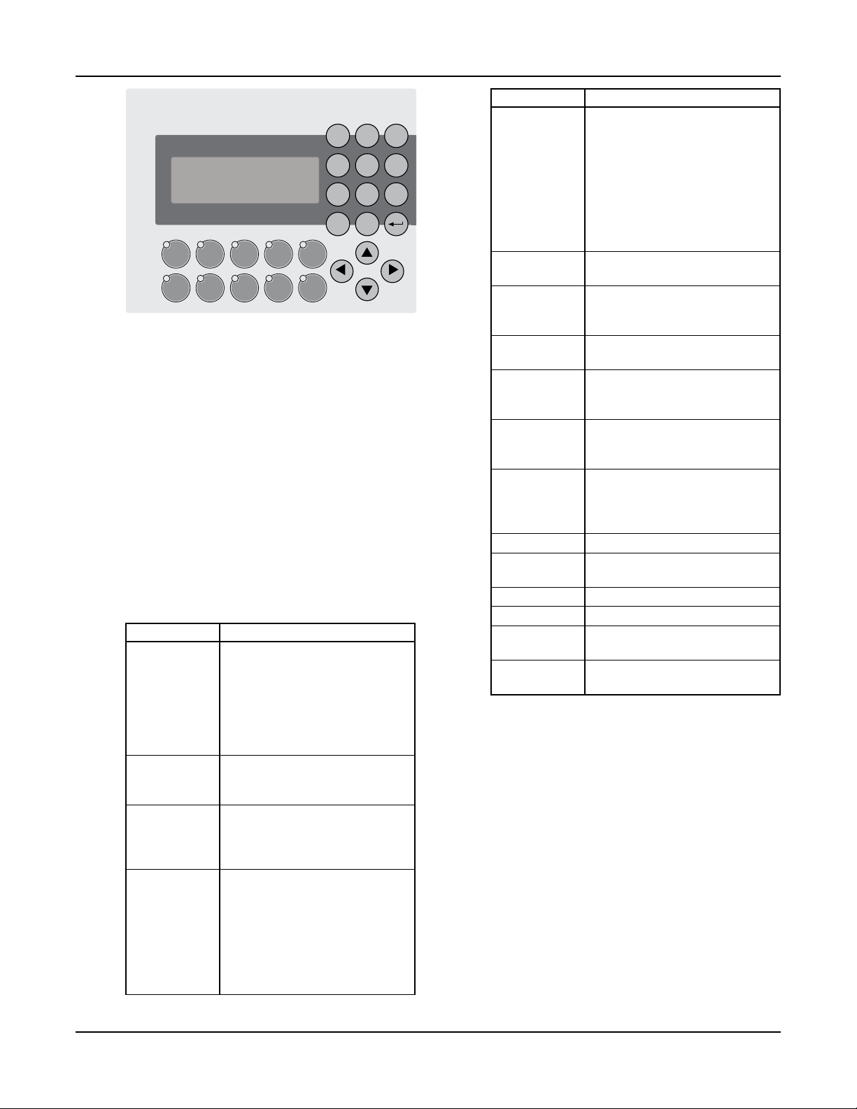
Section 2 — Operator Interface Panel
The OIP consists of a 4 x 20 character LCD screen
and a 26 button keypad with LEDs which display system status. It also is equipped with onboard I/O
including (16) 24VDC digital inputs, (4) 4-20mA
analog inputs, (2) PT100 RTD inputs, and an RS232/
RS485 serial port for communications all mounted
on the back of the OIP. The OIP communicates
through a CAN bus to the relay and power monitor
rack.
2.1 Key Functionality
The names of the keys on the Operator Interface
Panel (OIP) are shown as CAPITAL LETTERS in this
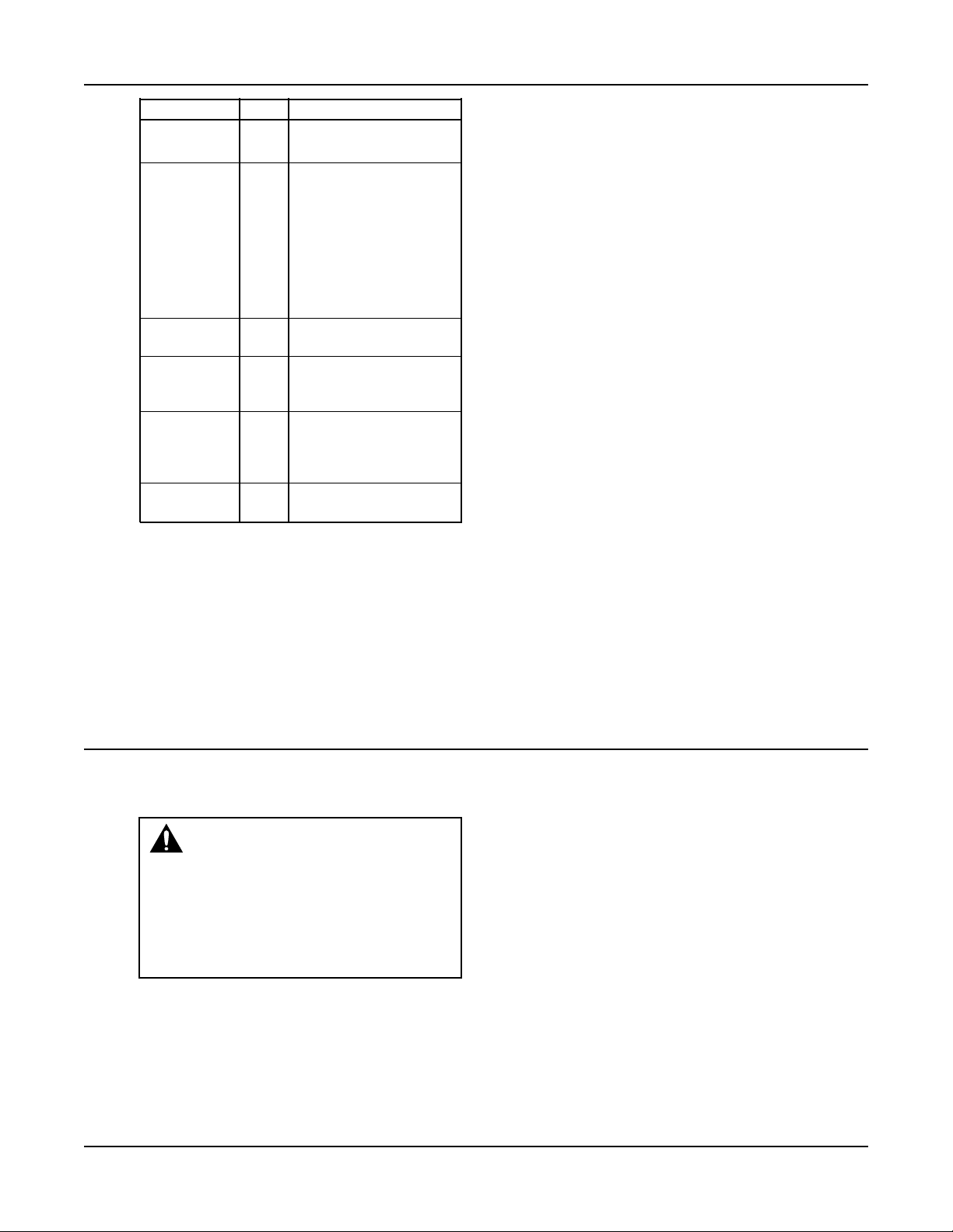
manual. Table 1 shows the functionality of the keys
on the OIP.
Note: The contrast can be adjusted from any screen
by pressing the UP and DOWN arrows while holding
the ENTER key.
Key Name Functionality
START/STOP Starts or stops the system. When
the Start/Stop method is not
“Keypad”, pressing the START/
STOP key will toggle between
“Ready” and “Stop”. “Ready”
indicates the system is waiting
for a remote signal to start.
AUTO/ Toggles the operation mode. The
MANUAL system must be stopped to
change the operation mode.
PUMP 1-6 Enables or disables the
ENABLE corresponding pump. Pumps
cannot be disabled while they
are failed.
RESET/ This key is used to reset pumps
Technologic® Constant Speed Pump Controller Installation, Operation and Maintenance Manual 8
SILENCE and alarms. When the A/V Alarm
relay output (section 4.3.8) is
set, initial pressing of this key
opens the relay to silence the
horn or turn off the pilot light.
Pressing a second time resets the
pumps and alarms.
Key Name Functionality
HELP Press the HELP button, from the
status screens, to view alarms or
events while the HELP LED is
flashing. While in the Alarm
screen, press the HELP button
again to view help messages for
active alarms. Press HELP any
other time to view screen
specific help messages.
YES/1 Press YES at OK prompts to
accept values and proceed
SETUP/3 Press SETUP, from the status
screens, to bring up the Setup
Menu shown in section 4
NO/4 Press NO at OK prompts to edit
the parameters
LOG/5 Press LOG, from the status
screens, to bring up the Log
Menu, shown in section 4.7
INFO/8 Press INFO, from the status
screens, to bring up the Info
screens, shown in section 5.5
ALT/9 Press ALT, from the status
screens, to manually alternate
the pump staging sequence, see
section 4.3.2
ENTER Confirms entries
CLEAR Clears entries or used to exit
some screens
PREV (←) Navigates to neighboring screens
NEXT (→) Navigates to neighboring screens
UP (↑) Used to modify values and
navigate to neighboring screens
DOWN (↓) Used to modify values and
navigate to neighboring screens
Table 1: Key Functionality
Page 9

2.2 LEDs
Table 2 gives the meaning of the LED states.
LED Description
START/STOP On = Start
Off = Stop
Blink Slow = Ready (waiting for
remote method)
AUTO/ On = Auto
MANUAL Off = Manual
PUMP 1-6 On = Pump On
Off = Pump Disabled
Blink Slow = Pump Ready
Blink Fast = Pump Failed
RESET/ Off = OK
SILENCE Blink Slow = Reset Required
Blink Fast = A/V Alarm output
is active
LED Description
HELP Off = OK
Blink Slow = Event (press HELP
from the status
screens to view)
Blink Fast = Alarm (press HELP
from the status
screens to view)
Table 2: LED Functionality
2.3 I/O
2.3.1 Analog Inputs
The Technologic
is equipped with 4 analog input channels. The analog
inputs must provide a 4-20mA signal. Typically, analog inputs will be powered by the 24V power supply
within the panel. For analog inputs which source
their own power, see the following section. See section 4.1 for more information on sensor setup.
Shielded 22 AWG cable should be installed for all
analog input wiring. The shield must be terminated
in the Technologic
Do not connect the shield at the other end of the
cable! Insulate the shield so that no electrical connection is made at the other end of the cable. A twisted
pair of #22 AWG conductors can be used in place of
shielded cable. The cable length must be limited to
5,000 feet for #22 AWG wire.
®
Constant Speed Pump Controller
®
Constant Speed Pump Controller.
Operator Interface Panel
1) Turn off all power to the Technologic
Speed Pump Controller.
2) Refer to the appropriate controller wiring diagram
that was shipped with unit. Locate the analog
input sensors on the wiring diagram that will be
rewired. They are labeled AI1 – AI4.
3) Remove the 24 VDC positive (+) wire from TB 40
for the respective analog input sensor connection.
This wire needs to be removed completely or terminated if used as a jumper. This will prevent any
accidental contact with a negative (-) voltage
source (i.e. control panel) and avoid becoming a
short circuit. Care should be taken to ensure that
24 VDC positive (+) voltage is still provided to
any remaining sensors that will be powered by the
Technologic
®
Constant Speed Pump Controller.
4) Remove the 24 VDC negative (-) wire from TB 41
for the respective analog input sensor connection.
This wire needs to be removed completely or terminated if used as a jumper. This will prevent any
accidental contact with a positive (+) voltage
source and avoid becoming a short circuit. Care
should be taken to ensure that 24 VDC (-) negative voltage is still provided to any remaining sensors that will still be powered by the Technologic®
Constant Speed Pump Controller.
5) Terminate the negative (-) wire of the sensor to TB
41 of the respective analog input sensor connection. Terminate the positive (+) wire of the sensor
to the terminal block which is connected to the
positive (+) terminal shown on the Analog input
card.
Note: Be certain that the power supplied to other
terminal blocks has not been interrupted! The wires
that were removed in the preceding steps may have
been used as jumpers.
2.3.3 RTD Inputs
®
The Technologic
Constant Speed Pump Controller
is equipped with (2) PT100 RTD input channels. (2)
RTDs will be shipped with standard units. The system RTD will be factory mounted, on the suction
header, unless the control panel is sold separate from
the pump package. The suction RTD will be shipped
loose inside the control panel and will need to be
field mounted upstream of the suction header.
®
Constant
2.3.2 Powered Analog Inputs
The following steps describe the general procedure
for wiring an analog input when the sensor’s power
source is not the Technologic
®
Constant Speed Pump
Controller.
2.3.4 Digital Inputs
The Technologic
is equipped with (16) 24VDC digital input channels.
This signal voltage must be obtained from the 24VDC
power supply mounted to the subpanel. It is not rec-
®
Constant Speed Pump Controller
ommended that other power sources be used without
WARNING: Prevent electrical shocks.
Disconnect the power supply before begin-
ning installation. FAILURE TO FOLLOW
factory approval. All digital inputs are automatically
assigned based on Table 3. See the typical wiring diagram in Appendix H.
THESE INSTRUCTIONS COULD RESULT IN
SERIOUS PERSONAL INJURY, DEATH AND/
OR PROPERTY DAMAGE.
Technologic® Constant Speed Pump Controller Installation, Operation and Maintenance Manual 9
Page 10
Operator Interface Panel
Functionality DI # Description
1M-6M 1-6 Motor starter feedbacks
Feedback (generate overload alarm)
Start/Stop Sw 7 Remote contact can be
used to start/stop the
system. The start/stop
method must be set to
Remote. See section 4.3.4.
“Rem” will be displayed in
the Tech Status screen
shown in section 3.4.1
when this method is active.
Flow Switch 8 Used for no flow shut-
down, see section 4.5.6.
Pressure Sw 9 Used to detect low suction
pressure alarm or event,
see section 4.5.4.
Low Level 10 Low level relay to sense a
low level condition in a
tank. All pumps will stop
when active.
DP 1-6 11-16 Differential pressure
switches
Table 3: Digital Inputs Functionalities
# 22 AWG cable should be installed for all field wir-
ing to digital inputs.
2.3.5 Relay and Power Monitor Rack
The relay and power monitor rack consists of an
EX270 CAN bus controller, a DO722 digital output
module and an AI984 power measurement module.
2.3.5.1 Digital Output Module
The digital output module consists of 8 normally
open single pole single throw relays rated at 2.5A at
either 240VAC or 24VDC. One relay will be used to
energize the coil of each motor starter. These will be
factory wired. Customer connections are made directly to the terminals mounted on the digital output
module. If a relay is defective, the digital output
module must be replaced. Refer to section 4.3.8 for
relay output setup.
2.3.5.2 Power Measurement Module
The power measurement module calculates total
power by measuring the incoming voltage and the
total current from the current transformer.
2.3.5.3 Current Transformer
The current transformer (ct) comes in three different
sizes measuring up to 40A, 150A, or 400A. It plugs
directly into the AI984 module on the relay and
power monitor rack. The ct measures the total amp
draw of all motors in the system. The four digit hex
numbers displayed on the label on the current transformer are calibration values, unique to each ct, that
have been input into the controller prior to shipment.
See section 5.5 to view the values used.
Section 3 — Operation
3.1 Power-Up
Turn the disconnect switch “ON” to power up the controller.
WARNING: Electrical shock hazard.
Inspect all electrical connections prior to
powering the unit. Wiring connections must be
made by a qualified electrician in accordance with
all applicable codes, ordinances and good practices. FAILURE TO FOLLOW THESE INSTRUC-
TIONS COULD RESULT IN SERIOUS
PERSONAL INJURY, DEATH AND/OR
PROPERTY DAMAGE.
In order to recover from a power loss, the controller
will start up in the operating mode that it was in
prior to the last shutdown. On power up, the controller will display the Tech Status screen shown in
section 3.4.1.
Technologic® Constant Speed Pump Controller Installation, Operation and Maintenance Manual 10
3.2 Basics of Screen Navigation and User
Setup
Numeric inputs (represented by the # symbol) must
be input from the numeric keypad. Text fields (represented by the $ symbol) must be modified by using
the UP and DOWN arrow keys. For numeric or text
fields, ENTER must be pressed to confirm values.
The arrow keys are also be used to navigate to neigh-
boring screens. Flashing arrows shown on the display
indicate when the corresponding arrow keys are
active.
An OK prompt is used in most user setup screens.
Press NO (the number 4 key) followed by ENTER at
the OK prompt to edit the parameters shown, or
press YES (the number 1 key) followed by ENTER to
accept the values and exit the screen.
The YES/1 and NO/4 keys are also used for text
inputs for some parameters. They will appear as “Y”
or “N” when a text input is required.
Page 11

Operation
The CLEAR key is also used to exit some screens
including: Log screens, Test screens, Info screens, and
the Alarm screen.
3.3 Pump Operation
The pumps can be controlled manually or automati-
cally. See the following sections for instructions on
both types of operation.
3.3.1 Manual Pump Operation
To manually control the pumps with the controller,
the operation mode must be set to Manual by pressing the AUTO/MANUAL key. Note that this key is
not allowed unless the system is stopped. The Auto/
Manual LED will be off to indicate manual operation. The system must also be started by pressing the
START/STOP key. The Start/Stop LED will be on to
indicate the system is started.
Pumps are automatically disabled when operation
mode is changed to manual. Press the corresponding
PUMP ENABLE keys to start or stop pumps. The
corresponding LED will turn solid green to indicate a
pump is on.
3.3.2 Automatic Pump Operation
To automatically control the pumps with the control-
ler, the operation mode must be set to Auto by pressing the AUTO/MANUAL key. Note that this key is
not allowed unless the system is stopped. The Auto/
Manual LED will be on to indicate automatic operation. The system must also be started by pressing the
START/STOP key. The Start/Stop LED will be on to
indicate the system is started.
During automatic pump operation, the pumps will
turn on or off based on the primary staging method.
If more pumps are required to meet the system
demand, they will stage on as required. When the
system demand is met, and the minimum pump run
timer is met, the pumps will destage until only one
pump is running. When there is no demand in the
system, the no flow shutdown alarm or event will
occur, shutting down the last running pump. During
this sequence, alarms may occur that shut down a
specific pump or all of the pumps. Various automatic
pump alternation methods may be used to alternate
the pump sequence at any time.
View the status screens, shown in section 3.4, to get
system information including on/off or auto/manual
status, pump status, sensor values, or staging status.
3.4 Status Screens
The status screens are the main level in screen naviga-
tion and show most of the relevant system information. The status screens can be scrolled by pressing
PREV or NEXT.
The Setup Menu(3), Log Menu(5), Info screens(8),
Ma n ua l Al t er na ti on scr ee n( 9) , and Ala r m
screen(HELP) are only accessible from the status
screens.
All of the status screens will display “Alm”, “Evt”, or
“NFSD” in the lower right corner if an alarm or
event or NFSD condition exists. If this message is
flashing, press the HELP key for more details.
3.4.1 Tech Status
The Tech Status screen, shown below, is the first of
the status screens. This screen is displayed on power
up. See Table 4 below for a description of the Tech
Status variables.
← TECH STATUS →
HH:MMam MM/DD/YY
Stop :(Method)
Manual Alm
Variable Description
Start/Stop/ Stop: System is stopped. Pumps
Ready will not start.
Start: System is started. The
pumps can be controlled manually
or automatically.
Ready: System is waiting for
remote start/stop method,
see section 4.3.4.
Press the START/STOP button
to toggle.
Method System Start/Stop Method, see
section 4.3.4.
Key: Keypad
Rem: Remote contact
Sch: Scheduled start/stop
Ser: Serial Communications
Auto/Manual Manual: System is in manual
operation mode. The user can
manually start and stop the pumps
by pressing the corresponding
Pump On/Off key.
Auto: The system is in automatic
operation mode. The pumps will
be controlled automatically based
on the user setup info.
Press the AUTO/MANUAL key
to toggle.
Table 4: Tech Status Variables
3.4.2 Pump Status
Pressing NEXT, the controller will display the Pump
Status screen shown below. See Table 5 for a description of the Pump Status variables.
← PUMP STATUS →
1:On 2:On 3:Off
4:Rdy 5:Fail 6:Rdy
Alm
Technologic® Constant Speed Pump Controller Installation, Operation and Maintenance Manual 11
Page 12

Operation
Variable Description
P1-P6 On: pump is running
Off: pump is disabled from the
keypad
Rdy: pump is enabled but not
running
Fail: pump is failed
Table 5: Pump Status Variables
3.4.3 Sensor Status
Pressing NEXT, the controller will display the Sensor
Status screen shown below. See Table 6 for a description of the Sensor Status variables.
←Suc Press= ###→
Sys Press= ###
Suc Temp=###.#
Sys Temp=###.# Alm
Variable Units Description
Suc Press PSI Suction Pressure
Sys Press PSI System (discharge) Pressure
Suc Temp °F Suction Temperature
(mounted upstream of the
suction header)
Sys Temp °F System Temperature
(mounted on the suction
header)
Table 6: Sensor Status Variables
3.4.4 Staging
Pressing NEXT, the controller will display the Staging
screen shown below. See Table 7 for a description of
the Staging variables.
←STAGING: (Type)→
Stg Seq:1-2-3-4-5-6
Dstg: #### Stg: ####
Actual: ###.# Alm
Variable Description
Type Type will display the active staging
method.
Stg Seq Pump staging sequence from left
to right. A 0 indicates that a pump
is failed or disabled. See section
4.3.2 for information on alternat ing the staging sequence.
Stg Next staging value (N/A indicates
end of staging sequence or no
staging values set up)
Variable Description
Dstg Next destaging value (N/A indi-
cates end of destaging sequence
or no destaging values set up)
Actual Current value of the staging
variable
Table 7: Staging Variables
Note: “Stg” and “Dstg” will be displayed in units of
the active staging method shown in the “Type” field.
To change the staging type or values, see section
4.3.1.
3.4.5 Timers
Pressing NEXT, the controller will display the Timers
screen shown below. The numeric values on the left
are elapsed times, and the numeric values on the right
are the limits that they must reach prior to performing their respective action. See Table 8 for a description of the Staging variables.
←Pump MnRn:##/##m→
NFSD MnRn:###/###m
Stg PT:##/##
Dstg PT:##/## Alm
Variable Units Description
Pump Min Minutes Pump minimum run time,
Run see section 4.3.1.3. When the
timer reaches its limit pumps
will be allowed to destage.
NFSD Minutes No flow shutdown minimum
MnRn run time, see section 4.5.6.
When the timer reaches its
limit, a no flow shutdown
will be allowed to occur. Note
that the timer immediately
resets to zero after expiring.
Stg PT Seconds Staging proof timer, see
section 4.3.1.1. When the
timer reaches its limit,
another pump will stage on.
Dstg PT Seconds Destaging proof timer, see
section 4.3.1.1. When the
timer reaches its limit, a
pump will stage off.
Table 8: Timers Variables
3.4.6 Power
Pressing NEXT, the controller will display the Power
screen shown below.
← POWER→
HP= ###.# PF= #.##
Volts= ###.#
Amps = ###.# Alm
Technologic® Constant Speed Pump Controller Installation, Operation and Maintenance Manual 12
Page 13

Operation
Variable Units Description
HP Horse- Total power measured by
power the power module
Volts Volts Average voltage measured by
the power module
Amps Amps Total current measured by the
power module
PF N/A Power factor measured by the
power module
Table 9: Power Variables
3.4.7 Optional Sensors
Pressing NEXT, the controller will display the
Optional Sensors screen shown below if any optional
sensors are set up. If they are not, the Optional
Sensors screen will be skipped. See section 4.1 for
information on sensor setup.
←OPTIONAL SENSORS→
Temp =### Flow=#####
Diff Temp= ###
Pressure = ### Alm
Variable Units Description
Temp °F Optional temperature
Diff Temp °F Optional differential
temperature
Pressure PSI Optional pressure
Flow GPM Optional flow
Table 10: Optional Sensor Variables
3.5 Alarms/Events
Some conditions can be defined as alarms or events,
while others are predefined to be alarms. See section
4.5 for alarm setup. Alarms are logged in the Alarm
Log and events are logged in the Events Log. See section 4.7 for logging. An alarm triggers the General
Alarm serial communications point and the A/V
Alarm relay output. An event will not trigger either
of these. See Appendix C for the serial communications points list and section 4.3.8 for relay outputs
setup.
Some alarms or events will cause one or all of the
pumps to shut down. For Low System Pressure, the
user can define if the pumps will shut down or not.
All alarms or events require either a manual or auto-
matic reset. The RESET/SILENCE LED will flash
when a manual reset is required. Press the RESET key
to manually reset the system.
The values in parentheses in Table 11 are the default
values.
Technologic® Constant Speed Pump Controller Installation, Operation and Maintenance Manual 13
Page 14

Operation
Description Alarm or Event Pump Shutdown Reset Conditional Upon Help Message
Pump 1-6 DP Alarm Individual Manual Started Check DP switch, im Fail peller, coupler, motor
Pump 1-6 Alarm Individual Manual Started Check motor amp
Overload Fail draw and use manual
reset if ok
Low System User Defined User Defined (No) Auto always active, Started and Auto Check PRV setting
Pressure (Event) Manual reset is and trip point
allowed if Stop
Pumps or Alarm is
set to “Y”
High System Alarm Yes Manual Started and Auto Check PRV setting
Pressure and trip point
Low Suction User Defined Yes Manual always Started and Auto Check suction pressure
Pressure (AI) (Event) active, auto reset is and trip point
allowed if “Auto
Reset” is set to “Y”
Low Suction User Defined Yes Manual always Started and Auto Check suction pressure
Pressure (Sw) (Event) active, auto reset is and trip point
allowed if “Auto
Reset” is set to “Y”
High Suction User Defined Yes Auto Started and Auto Check suction pressure
Pressure (Event) and trip point
No Flow Shut User Defined Yes Auto Started and Auto and NFSD is active, check
Down (AI) (Event) only 1 pump on restart pressure
No Flow Shut User Defined Yes Auto Started and Auto and NFSD is active, check
Down (Sw) (Event) only 1 pump on restart pressure
High Alarm Yes Auto Started and Auto Check water temp Temperature erature and trip point
Low Level Alarm Yes Auto Started and Auto Check water level in
holding tank
AI 1-4 Fail Alarm No Auto Always active Check wiring, piping,
polarity and continuity
RTD 1-2 Fail Alarm No Auto Always active Check wiring and
continuity
Battery Alarm No Auto Always active Replace OIP battery
CAN Fail Alarm No Auto Always active Set EX270 switches
C (top), 2 (bottom),
check wiring
Volt Tol. Alarm Yes Auto Always active Check voltage reading
and trip point
Voltage Alarm No Auto Always active Check AI984 connec tion and voltage inputs
Table 11: Alarms/Events
The LED on the HELP key will flash to indicate that an alarm or event exists. The Status screens will also flash “Alm”,
“Evt”, or “NFSD” in the lower right corner to indicate that an alarm or event exists. Pressing the HELP key, while in the
status screens, will display all of the active alarms or events as shown in the screen below. Blinking arrows will indicate
UP/DOWN can be pressed to view more alarms or events. Press CLEAR to exit this screen, or press HELP again while in
the Alarms screen to view help messages for each alarm.
Pump1 Ovld Press ↑
AI#1 Fail Clear to
Pump2 Fail Exit
Hi Sys Pr ↓
Technologic® Constant Speed Pump Controller Installation, Operation and Maintenance Manual 14
Page 15

Section 4 — Setup Menu
From the status screens, shown in section 3.4, press
the SETUP key to get to the Setup Menu shown
below. Field values columns are provided to record
user setup information for future reference. For the
remainder of this manual, the path to navigate to a
particular screen will be given as follows: Path: Status
Screens/Setup(3).
Setup Menu: # 0=Exit
1=Sensors 4=Test
2=Pumps 5=Alrm/Evt
3=System 6=EZ-Start
4.1 Sensor Setup
Path: Status Screens / Setup (3) / Sensors (1)
← Sensor Setup→
AI#:# (Type)
Span= #### Zero=####
OK? $ (Y/N)
While the left and right arrows are flashing, press
PREV or NEXT to scroll through all of the analog
inputs and RTDs that can be set up. Press UP/DOWN
to modify the sensor type when it is flashing. Input
the span (the sensor value that corresponds to a
20mA signal), then input the Zero (the sensor value
that corresponds to a 4mA signal). Table 12 shows
the default values for each analog input or RTD.
Table 13 shows all of the possible analog input or
RTD types.
Sensor Default Default Default Field Field Field
Number Type Span Zero Type Span Zero
AI #1 Suc Press 100 0
AI #2 Sys Press 300 0
AI #3 None 0 0
AI #4 None 0 0
RTD #1 Suc Temp N/A N/A
RTD #2 Sys Temp N/A N/A
Table 12: Sensor Setup Variables
Analog Input Types RTD Types
None None
Suc Press Suc Temp
Sys Press Sys Temp
Flow Sup Temp
Temp Ret Temp
Press
Diff Temp
Table 13: Possible Sensor Types
Note: Only one sensor of each type can be set up. If
a type is chosen that is already used for another sen-
sor or RTD channel, the other sensor or RTD input
will be given a type of “None”.
4.2 Pump Setup Menu
Path: Status Screens / Setup (3) / Pumps (2)
Pump Menu: # 0=Exit
1=Number of Pumps
2=Nameplate Data
3=Reset Pmp Runtime
4.2.1 Number of Pumps
Path: Status Screens / Setup (3) / Pumps (2) / Number
of Pumps(1)
Total # Pumps: #
# Jockey Pumps: #
# Standby Pumps: #
OK? $ (Y/N)
See Table 14 for a description of the variables.
Variable Description
Value Value
Total # The total number of 3 1-6
Pumps pumps in the system.
# Jockey pumps will always 0 0-5
Jockey be first in the staging
Pumps sequence. Alternation will
not change this designation.
Jockey Pumps will be
assigned to the lowest
pump numbers starting
with Pump # 1.
# A standby pump will only 0 0-5
Standby operate if a duty pump
Pumps fails. The last pumps in the
staging sequence will be
designated as the standby
pumps.
Table 14: Number of Pumps Variables
4.2.2 Pump Nameplate Data
Path: Status Screens / Setup (3) / Pumps (2) /
Nameplate Data (2)
← Pump# 1 Data →
HP : ###.#
Amps: ###.#
GPM : #### OK? $
Press PREV or NEXT to scroll though all of the
pumps. See Table 15 for a description of the variables.
Default
Range
Field
Technologic® Constant Speed Pump Controller Installation, Operation and Maintenance Manual 15
Page 16

Setup Menu
Variable Description
Value Value
HP Enter the horsepower from Actual 0 the nameplate of the motor. 999.9
These values are required
for power staging.
Amps Enter the full load amps 0 0 from the motor nameplate. 999.9
These values are required
for amps staging.
GPM Enter the maximum GPM 0 0 from the pump nameplate. 999.9
These values are required
for flow staging.
Table 15: Pump Nameplate Data Variables
Note: All values will be copied to the next screen by
pressing NEXT. They will only be copied the first
time the screens are visited.
Default
Range
Field
4.3 System Setup Menu
Path: Status Screens / Setup (3) / System (3)
System Menu: # ↑
0=Exit
1=Staging
2=Alternation ↓
System Menu: # ↑
3=Exercise
4=Start/Stop
5=Scheduling ↓
System Menu: # ↑
6=Date/Time
7=Password
8=Relay Outputs ↓
System Menu: # ↑
9=Save/Load
*10=Communications
*11=Tech 350 ↓
Press UP/DOWN to view the entire menu.
*Note: depending on factory setup, menu items 10
and 11 may or may not be available
4.3.1 Stage Menu
Path: Status Screens/Setup(3)/System(3)/Staging(1)
Stage Menu:# 0=Exit
1=Primary Staging
2=Secondary Staging
3=Force Dstg/Min Run
4.3.1.1 Primary Staging
Path: Status Screens / Setup (3) / System (3) / Staging
(1) / Primary Staging (1)
Pri Stg Mthd: Method
Stg :###(U) PT: ##s
Dstg:###(U) PT: ##s
Dynamic Stg:$ OK? $
See Table 16 for a description of the Primary Staging
variables
Variable Units Description
Value Value
Pri Stg N/A Primary staging Power Power,
Mthd method. Power, Amps, Amps,
and flow staging Press,
require nameplate D Temp,
data to be set up. See Flow,
section 4.2.2. Temp
Stg (U) The value at which 80 0-999
pumps will stage on.
The units depend on the
staging type. This is the
stage 1-2 value and will
be used for each staging
occurrence unless Dy namic Stg is set to “Y”.
Dstg (U) The value at which 72 0-999
pumps will stage off.
The units depend on
the staging type. This is
the destage 2-1 value
and will be used for
each destaging occurr-
ence unless Dynamic
Stg is set to “Y”.
PT Sec- The proof timer that
onds will elapse before
staging pumps on/off. 5 5-99
Dynamic N/A Select “Y” for Dynamic N Y/N
Stg Stg to choose different
staging and destaging
values for each staging
occurrence. A separate
screen will be displayed
to allow for these inputs.
Table 16: Primary Staging Variables
If “Y” was selected for Dynamic Stg, the screen
shown below will be displayed.
Default
Range
Field
←Method Value Time→
Stg1-2: ###(U) ##s
Dst2-1: ###(U) ##s
OK? $ (Y/N)
Technologic® Constant Speed Pump Controller Installation, Operation and Maintenance Manual 16
Page 17

Setup Menu
The staging method chosen will be displayed in the
upper left corner. Press PREV or NEXT to scroll
through each staging occurrence. The staging num-
bers will increment to indicate which occurrence is
being shown. Set the value and the proof time for
each staging occurrence.
4.3.1.2 Secondary Staging
Path: Status Screens / Setup (3) / System (3) / Staging
(1) / Secondary Staging (2)
Sec Stg Mthd: Method
Stg :###(U) PT: ##s
Dstg:###(U) PT: ##s
Dynamic Stg:$ OK? $
See Table 17 for a description of the Secondary
Staging variables
Variable Units Description
Value Value
Sec Stg N/A Secondary staging Pressure Power,
Methd method. This will be Amps,
used if the sensor for Press,
the primary method D Temp,
fails. Power, Amps Flow,
and flow staging Temp
require nameplate
data to be set up.
See section 4.2.2.
Stg (U) The value at which System 0-999
pumps will stage on. Pressure
The units depend on the – 10
staging type. This is the
stage 1-2 value and will
be used for each staging
occurrence unless Dy namic Stg is set to “Y”.
Dstg (U) The value at which System 0-999
pumps will stage off. Pressure
The units depend on the – 3
staging type. This is the
destage 2-1 value and
will be used for each
destaging occurrence
unless Dynamic Stg is
set to “Y”.
PT Sec- The proof timer that 5 5-99
onds will elapse before
staging pumps on/off.
Dynamic N/A Select “Y” for Dynamic “N” Y/N
Stg Stg to choose different
staging and destaging
values for each staging
occurrence. A separate
screen will be displayed
to allow for these inputs.
Table 17: Secondary Staging Variables
Default
Range
Field
If “Y” was selected for Dynamic Stg, the screen
shown below will be displayed.
←Method Value Time→
Stg1-2: ###(U) ##s
Dst2-1: ###(U) ##s
OK? $ (Y/N)
The staging method chosen will be displayed in the
upper left corner. Press PREV or NEXT to scroll
through each staging occurrence. The staging numbers will increment to indicate which occurrence is
being shown. Set the value and the proof time for
each staging and destaging occurrence.
4.3.1.3 Force Destage/Minimum Pump Run Time
Path: Status Screens / Setup (3) / System (3) / Staging
(1) / Force Dstg / Min Run (3)
Force Dstg/Min Run
Force Dstg Tmr=##Min
Min Run Timer =##Min
OK? $ (Y/N)
See Table 18 for a description of the Force Destage/
Minimum Pump Run Time variables.
Variable Units Description
Value Value
Force Min- Maximum time a lag 60 0-99
Dstg utes pump will run prior
Tmr to destaging auto matically, a value of 0
disables forced
destaging. See section
3.4.5 for display of
timer status.
Min Min- Minimum time a lag 5 0-99
Run utes pump must run prior
Timer to destaging, a value
of 0 effectively dis ables the minimum
run timer. See section
3.4.5 for display of
timer status.
Table 18: Force Destage/Minimum Pump Run Time Variables
4.3.2 Alternation
Path: Status Screens / Setup (3) / System (3) /
Alternation (2)
Default
Range
Field
Alt Method: $$$$$
Basis:$$$$$ Dur:##s
Time:##:## Day: ##
Period:###Hrs OK? $
Technologic® Constant Speed Pump Controller Installation, Operation and Maintenance Manual 17
Page 18

Setup Menu
The pump staging sequence, which is shown in sec-
tion 3.4.4, may be alternated automatically or manu-
ally. To manually alternate the sequence, press ALT
from the status screens, then press “Y” and ENTER
at the prompt. Automatic and manual alternation
methods use the Basis and Dur variables shown
be low. See Table 19 for a d escrip t ion of t he
Alternation variables.
Variable Units Description
Value Value
Alt N/A Automatic Alter- None None,
nation Method Timed,
None: disables Daily,
automatic alternation Weekly,
Timed: alternates Monthly
based on the “Period”
Daily: alternates daily
based on the “Time”
Weekly: alternates
weekly based on the
“Time” and the “Day”
Monthly: alternates
monthly based on the
“Time” and the “Day”
Basis N/A Seq: the next pump in Seq Seq,
the sequence will Pmp
become the lead pump Tm
after alternation
Pmp Tm: the pump
with the lowest run time
will become the lead
pump after alternation
Dur Sec- Amount of time that 10 0-99
onds the running pumps will
remain on during
alternation
Time N/A Time, in 24hr format, 0:00 0:00 at which the pumps will 23:59
be alternated for daily,
weekly, or monthly
alternation
Day N/A Day of the week (1= 1 1-28
Monday…7=Sunday)
or month (day of month)
on which the pumps
will be alternated
Period Hours Time between pump 168 0-999
alternations when using
“Timed” alternation
Table 19: Alternation Variables
4.3.3 Pump Exercise
Path: Status Screens / Setup (3) / System (3) /
Exercise (3)
Default
Range
Field
Pump Exercise
Period : ###Hr
Duration : ###Sec
OK? $
Pump exercising will ensure that no pumps go for
long periods of time without running. Note that
automatic alternation can also provide this functionality. Pump exercising will only occur when the system is started and in automatic operation. All pumps
which need exercising will exercise on startup. All
exercising events will be logged in the Exercise Log
shown in section 4.7.5.5. See Table 20 for a description of the Exercise variables.
Variable Units Description
Value Value
Period Hours Amount of time between 0 0-999
automatic exercising of
the pumps, a value of 0
disables pump exercising
Dur- Sec- Amount of time pumps 0 0-999
ation onds will be exercised, all
pumps which have not
run in the last period
will be exercised
simultaneously
Table 20: Pump Exercise Variables
4.3.4 Start/Stop
Path: Status Screens / Setup (3) / System (3) / Start /
Stop (4)
Default
Range
Field
Start/Stop
Method: $$$$$$$$$
OK? $
The controller can be started or stopped in a variety
of ways. This method will always be displayed next
to the start/stop/ready status in the Tech Status screen
shown in section 3.4.1. See Table 21 for a description
of the Start/Stop Methods.
Variable Description
Value Value
Method Keypad: Use the keypad to Keypad Keypad,
start and stop the system Remote,
Remote: Use “Start/Stop
Sw” tied to DI #7
Serial: Use “System Start/
Stop” shown in appendix C
Scheduled: Use scheduling
to start and stop the system,
see section 4.3.5
Default
Table 21: Start/Stop Variables
Range
Serial,
Sched-
uled
Field
Technologic® Constant Speed Pump Controller Installation, Operation and Maintenance Manual 18
Page 19

Setup Menu
Note: When the Start/Stop Method is anything other
than “Keypad”, the START/STOP key must be
pressed to set the system “Ready” prior to using the
desired method. When the chosen method is active,
the START/STOP key can be pressed to start or stop
the system. If the chosen method is inactive, the
Start/Stop Method must be set back to “Keypad” to
start the system from the keypad.
4.3.5 Scheduling
Path: Status Screens / Setup (3) / System (3) /
Scheduling (5)
← Scheduling →
Day
ON @ : ##:##AM
Off @: ##:##AM OK? $
Press PREV or NEXT to change the day for which
scheduling will be set up. See Table 22 for a descrip-
tion of the Scheduling variables.
Variable Description
ON @ Time at which the system will
automatically start. Set the hour to
0 to prevent the system from starting
on this day.
Off @ Time at which the system will
automatically stop. Set the hour to
0 to prevent the system from stopping
on this day.
AM/PM Press UP/DOWN to select AM/PM
Table 22: Scheduling Variables
Note: Scheduling must be set up as the start/stop
method, for it to take effect. See section 4.3.4 for
more information on the start/stop method. Also, the
controller must be powered up at the specified times,
or it will remain in the previous state until the next
scheduled on or off time.
4.3.6 Date/Time
Path: Status Screens / Setup (3) / System (3) /
Date/Time (6)
Date: MM/DD/YYYY
Time: HH:MM:SS am/pm
Daylite Saving Tm:$
OK? $ (Y/N)
Variable Description
MM Current month (two digits), example:
Jan. should be created as 01
DD Current date (two digits), example:
the 6th should be entered as 06
YYYY Current year using all 4 digits
HH Hours
MM Minutes
am/pm Use UP/DOWN to toggle am/pm
Daylite Enter “Y” for automatic set back
Saving Tm during daylight saving time.
Table 23: Date/Time Variables
4.3.7 Password
Path: Status Screens / Setup (3) / System (3) /
Password (7)
Enable Password
For Setup Menu?: $
OK? $ (Y/N)
If the above is set to YES, the user will be prompted
to input a password prior to entering the Setup
Menu. Upon exiting the above screen, the user will
be prompted to define and confirm a new password.
The password must be a numeric value (0-99999).
Record it here or somewhere else!
_______________________
4.3.8 Relay Outputs Setup
Path: Status Screens / Setup (3) / System (3) /
Relay Outputs (8)
← Digital Outputs →
DO# 1 Locked
(Functionality)
OK? $
Press PREV or NEXT to scroll through the digital
outputs. Its output number and functionality will be
displayed. If a digital output is “Unlocked”, it may be
modified. Use UP or DOWN to modify the functionality. Multiple outputs may have the same functionality.
See Table 23 for a description of the Date/Time Setup
variables.
Technologic® Constant Speed Pump Controller Installation, Operation and Maintenance Manual 19
Page 20

Setup Menu
Functionality Description
1M-6M Relay used to energize motor starter
Output coil or can be used as pump run
status
General Relay closes to indicate an “alarm”
Alarm condition exists (will not indicate
an “event”)
System On Relay closes when the system is
started
System Auto Relay closes when the system is in
automatic mode
A/V Alarm Relay closes to indicate an “alarm”
condition exists (will not indicate an
“event”), this output is intended to
be connected to a pilot light or a
horn. When this output is active,
the RESET/SILENCE LED will blink
fast to indicate it should be pressed
to deactivate this output. Once this
output is deactivated, the RESET/
SILENCE key will function
normally to reset pumps and alarms.
Table 24: Optional Digital Outputs
Note: 1M-6M outputs will be automatically assigned
to digital outputs according to the appropriate wiring
diagram depending on the number of pumps that are
set up. These outputs will always be “locked” and
cannot be modified.
4.3.9 Save/Load Menu
Path: Status Screens / Setup (3) / System (3) /
Save/Load (9)
Sav/Ld Menu:# 0=Exit
1=Save to Flash
2=Load from Flash
3=Load Defaults
4.3.9.1 Save to Flash
Path: Status Screens / Setup (3) / System (3) /
Save/Load (9) / Save to Flash (1)
PREVIOUS SAVED
DATA WILL BE
OVERWRITTEN!
Proceed? $
Press YES and ENTER to save all of the user setup to
the flash memory. Saving to flash will overwrite any
data that was previously saved. A load from flash will
have to be performed to recover this saved data. See
the following section.
4.3.9.2 Load from Flash
Path: Status Screens / Setup (3) / System (3) /
Save/Load (9) / Load from Flash (2)
ALL USER SETUP
DATA WILL BE
LOADED FROM FLASH
Proceed? $
Press YES and ENTER to overwrite all of the current
user setup information with the data that was previously saved to the flash memory.
4.3.9.3 Load Defaults
Path: Status Screens / Setup (3) / System (3) /
Save/Load (9) / Load Defaults (3)
ALL USER SETUP
DATA WILL BE
OVERWRITTEN BY
DEFAULTS! Proceed? $
Press YES and ENTER to overwrite all of the current
user setup information with the factory defaults.
4.3.10 Communications
Selecting 10 from the System Setup Menu will dis-
play the appropriate communications setup screen
shown in the following sections. If no communications were set up by the factory, this menu option
will not be available. If the communication type displayed is not the type of communications desired, call
your Bell & Gossett representative for assistance in
changing it.
Refer to Appendix C for the list of serial communica-
tions points that are available for each protocol.
4.3.10.1 BACnet MS/TP
Path: Status Screens / Setup (3) / System (3) /
BACnet (10)
Enable BACnet: $
Baud,8,1,1,N Slave
MAC=### Inst=###
AI Ovrd: $ OK?$
The Technologic® Constant Speed Pump Controller
communicates using 8 bit data packets, 1 stop bit, 1
sta r t bit a nd n o p ar i ty. See t he P r ot o co l
Implementation Conformance statement in appendix
D for details on the supported objects and services.
Technologic® Constant Speed Pump Controller Installation, Operation and Maintenance Manual 20
Page 21

Setup Menu
Variable Description
Value Value
Enable This must be set to “Y” to Y Y/N
BACnet utilize RS-485 communi cations. It should only be
set to “N” to upload
software upgrades.
Baud The baud rate is user 9600 9600,
adjustable 19200,
38400
MAC The MAC address or node 10 1-255
Address number should be supplied
by the BMS.
Inst Unique instance numbers 100 0-9999
should be assigned for
every device on a BACnet
network.
AI Select “Y” to override N Y/N
Ovrd analog inputs through the
communications port.
See section 4.3.10.5.
Table 25: BACnet MS/TP Variables
4.3.10.2 Metasys N2
Path: Status Screens / Setup (3) / System (3) /
JC N2 (10)
Default
Range
Field
Enable Metasys N2: $
9600,8,1,1,N VND
Node=###
AI Ovrd: $ OK?$
See Table 26 for a description of the Metasys N2
variables.
®
The Technologic
communicates using 9600 bps baud rate, 8 bit data
packets, 1 stop bit, 1 start bit and no parity.
Constant Speed Pump Controller
4.3.10.3 Modbus
Path: Status Screens / Setup (3) / System (3) /
Modbus (10)
Enable Modbus: $
9600,8,1,1,N VND
Node=###
AI Ovrd: $ OK?$
See Table 27 for a description of the Modbus vari-
ables.
®
The Technologic
communicates using 9600 bps baud rate, 8 bit data
packets, 1 stop bit, 1 start bit and no parity.
Variable Description
Value Value
Enable This must be set to “Y” to Y Y/N
Modbus utilize RS-485 communi cations. It should only be
set to “N” to upload
software upgrades.
Node The node number should 10 0-255
be supplied by the BMS.
AI Select “Y” to override N Y/N
Ovrd analog inputs through the
communications port.
See section 4.3.10.5.
Table 27: Modbus Variables
4.3.10.4 Lonworks
Path: Status Screens / Setup (3) / System (3) /
Lonworks (10)
Constant Speed Pump Controller
Default
Range
Field
Enable Lonworks: $
AI Ovrd: $
OK?$
Variable Description
Value Value
Enable This must be set to “Y” to Y Y/N
Metasys utilize RS-485 communi N2 cations. It should only be
set to “N” to upload
software upgrades.
Node The node number should 10 0-255
be supplied by the BMS.
AI Select “Y” to override N Y/N
Ovrd analog inputs through the
communications port.
See section 4.3.10.5.
Technologic® Constant Speed Pump Controller Installation, Operation and Maintenance Manual 21
Default
Table 26: Metasys N2 Variables
Range
Field
See Table 28 for a description of the Lonworks vari-
ables.
®
The Technologic
communicates using Modbus over RS-232 media
through a gateway, supplied with the panel, which
converts the protocol to Lonworks.
Note: Lonworks requires additional hardware.
Variable Description
Value Value
Enable This must be set to “Y” Y Y/N
Lon- to enable Lonworks
works communications.
AI Select “Y” to override N Y/N
Ovrd analog inputs through the
communications port.
See section 4.3.10.5.
Table 28: Lonworks Variables
Constant Speed Pump Controller
Default
Range
Field
Page 22

Setup Menu
4.3.10.5 Analog Input Override
If “Y” was entered for “AI Ovrd” in any of the com-
munication setup screens above, the following screen
will be automatically displayed.
AI Override
Suc P:$ D Temp:$
Sys P:$ Press:$
Flow :$ Temp:$ OK?$
Enter a “Y” next to each analog input type that will
be overridden through the communications port.
4.3.11 Tech 350
Path: Status Screens / Setup (3) / System (3) /
Tech 350 (11)
Tech 350
Purge Time: ##Min
Purge Num Pumps: #
App Type: $$$$ OK?$
This setup menu will only be available for closed sys-
tems. If purging is enabled, purging will occur every
time the system is started in automatic mode. Every
time purging occurs it will be logged. See section
4.7.5.4 for purge logging. See Table 29 for a descrip-
tion of the Tech 350 variables.
Variable Units Description
Value Value
Purge Min- Time that the pumps 10 0-30
Time utes will run immediately
after starting the
system in automatic
mode, a value of 0
disables purging
Number N/A Number of pumps 1 0-6
of that will turn on when
Pumps purging is active
App N/A The application type Cool Heat,
Type is required if staging Cool
will be based on
temperature.
Table 29: Tech 350 Variables
Default
Range
Field
4.4.1 Digital Input Test
Path: Status Screens / Setup (3) / Test (4) / DI (1)
Digital Input Test
1234567890123456
################
Press Clear to Exit
The 0 below each corresponding input will change to
a 1 upon receiving a 24VDC digital input on that
channel. Press CLEAR to exit the test.
4.4.2 Digital Output Test
Path: Status Screens / Setup (3) / Test (4) / DO(2)
Digital Output Test
12345678
########
Enter DO# # (0=Exit)
Press the numeric key corresponding to the digital
output for which the state is to be changed, and then
press ENTER to change it. Pressing ENTER multiple
times will toggle between 0 and 1. A 1 indicates that
the corresponding relay is closed. When the relay is
closed, the corresponding LED on the digital output
module will be lit. Press 0 and ENTER to exit the
test.
Note: Motors will start if the corresponding relay is
actuated.
4.4.3 Analog Input Test
Path: Status Screens / Setup (3) / Test (4) / AI (3)
Analog Input Test
AI1=###% AI4 =###%
AI2=###% RTD1=###.#F
AI3=###% RTD2=###.#F
The signal received on the corresponding analog input
channel will be indicated in percent next to each
input. 0mA = 0%, and 20mA = 100%. Analog inputs
1-4 are 4-20mA inputs. RTD1 and RTD2 are for
PT100 resistive temperature devices. RTD1 and RTD2
are displayed in °F. Press CLEAR to exit the test.
4.4 Test Menu
Path: Status Screens / Setup (3) / Test (4)
Test Menu: #
0=Exit 3=AI 6=Disp
1=DI 4=LED 7=Comm
2=DO 5=Key
Press the numeric key corresponding to the desired
sub-menu, and press ENTER.
Technologic® Constant Speed Pump Controller Installation, Operation and Maintenance Manual 22
4.4.4 LED Test
Path: Status Screens / Setup (3) / Test (4) / LED (4)
LED Test
*** LED ON ***
*** LED OFF ***
*** LED BLINK ***
All of the LED’s on the keypad will turn on, off, and
then flash. The current status will be displayed on the
screen. The LED test is self terminating.
Page 23

Setup Menu
4.4.5 Key Test
Path: Status Screens / Setup (3) / Test (4) / Key (5)
Key Test
Press a key to test
Press clear to exit
Press any key except for the CLEAR key, and the dis-
play will confirm that the key is working by display-
ing the key name. Press CLEAR to exit.
4.4.6 Display Test
Path: Status Screens / Setup (3) / Test (4) / Disp (6)
The display will show all black characters. Press
CLEAR to exit.
4.4.7 Comm Test
Path: Status Screens / Setup (3) / Test (4) / Comm (7)
Comm Test
ITT Read: ####
ITT Write: ####
Press Clear to Exit
If the controller is communicating properly with the
building automation system, both numbers will con-
tinue increasing in value. For Modbus protocol, the
read and write numbers should be equal and increas-
ing with every poll. For BACnet, both numbers
should be increasing, but they will not be equal. The
write value will increase even when not connected.
For the Metasys N2 protocol, both numbers should
be increasing but may not be equal. This test feature
is not supported for Lonworks. If both numbers are
not increasing in value, the controller is not commu-
nicating properly. Check the wiring at the terminal
blocks. See section 4.3.10 for more information on
communications setup. Press CLEAR to exit this test.
4.5 Alarms/Events Menu
Path: Status Screens / Setup (3) / Alrm/Evt (5)
Alarm Menu: # 0=Exit
4=Low Suction ↑
5=High Suction ↓
6=NFSD
Alarm Menu: # 0=Exit
7=High Temp ↑
8=Low Level ↓
9=Volts Tolerance
Press UP/DOWN to view the entire menu.
4.5.1 Pump Failure
Path: Status Screens / Setup (3) / Alrm/Evt (5) /
Pump Failure (1)
Pump Failure
DP Switch Pr Tm: ##s
OK? $ (Y/N)
See Table 30 for a description of the Pump Failure
variables.
Variable Units Description
Value Value
DP Sec- Proof timer prior to 10 0-99
Switch onds setting a pump fail
Pr Tm alarm after receiving
a continuous high sig nal from a DP switch
Table 30: Pump Failure Variables
4.5.2 Low System Pressure
Path: Status Screens / Setup (3) / Alrm/Evt (5) /
Low System (2)
Default
Range
Field
Low Sys Press: ##PSI
Low Sys Pr Tm: ##s
Alarm:$ Stop Pumps:$
OK? $ (Y/N)
See Table 31 for a description of the Low System
Pressure variables.
Alarm Menu: # 0=Exit
1=Pump Failure ↑
2=Low System ↓
3=High System
Technologic® Constant Speed Pump Controller Installation, Operation and Maintenance Manual 23
Page 24

Setup Menu
Variable Units Description
Value Value
Low PSI The pressure below ½ 0-999
Sys which an alarm or System
Press event will be set Pressure
Low Sec- The proof timer prior 0 0-255
Sys onds to setting an alarm or
Pr Tm event. A value of 0
disables this alarm or
event.
Alarm N/A Set this value to “Y” N Y/N
to consider low system
pressure an alarm, or
set it to “N” to
consider it an event.
Stop N/A Set this value to “Y” N Y/N
Pumps to stop all pumps in
the event of a low
system pressure alarm
or event. Set it to “N”
to continue operation
normally during this
alarm or event.
Table 31: Low System Pressure Variables
4.5.3 High System Pressure
Path: Status Screens / Setup (3) / Alrm/Evt (5) /
High System (3)
Default
Range
Field
High Sys Press: ##
High Sys Pr Tm: ##s
OK? $ (Y/N)
See Table 32 for a description of the High System
Pressure variables.
Variable Units Description
Value Value
High PSI The pressure above 1.5 x 0-999
Sys which an alarm will System
Press be set Pressure
High Sec- The proof timer prior 20 0-255
Sys onds to setting an alarm.
Pr Tm A value of 0 disables
this alarm.
Table 32: High System Pressure Variables
4.5.4 Low Suction Pressure
Path: Status Screens / Setup (3) / Alrm/Evt (5) /
Low Suction (4)
Default
Range
Field
Low Suct Press: ##
Pr Tm: ##s Alarm:$
Auto Reset: $
Reset Press: ## OK?$
See Table 33 for a description of the Low Suction
Pressure variables.
Variable Units Description
Value Value
Low PSI The pressure below 5 0-999
Suct which an alarm or
Press event will be set for
the analog input
method
Pr Tm Sec- The proof timer prior 20 0-255
onds to setting an alarm or
event. A value of 0
will disable this alarm.
Used for analog input
and pressure switch
methods.
Auto N/A Select “Y” to allow Y Y/N
Reset this alarm or event to
be automatically reset.
The analog input
method resets using
the “Reset Press”. The
pressure switch
method resets on a
low signal on the low
suction pressure
switch digital input.
Reset PSI The pressure at which 10 0-999
Press the controller will
automatically reset
when the suction
pressure rises above it.
Used for the analog
input method only.
Alarm N/A Set this value to “Y” to N Y/N
consider low suction
pressure an alarm, or
set it to “N” to consider
it an event. Used for
analog input and
pressure switch
methods.
Table 33: Low Suction Pressure Variables
Note: The analog input and pressure switch methods
can be used simultaneously.
4.5.5 High Suction Pressure
Path: Status Screens / Setup (3) / Alrm/Evt (5) /
High Suction (5)
Default
Range
Field
High Suc Press: ##
High Suc Pr Tm: ##s
Reset Pressure: ##
Alarm:$ OK? $ (Y/N)
See Table 34 for a description of the High Suction
Pressure variables.
Technologic® Constant Speed Pump Controller Installation, Operation and Maintenance Manual 24
Page 25

Setup Menu
Variable Units Description
Value Value
High PSI The pressure above System 0-99
Suc which an alarm or Pressure
Press event will be set
High Sec- The proof timer prior 0 0-255
Suc onds to setting an alarm or
Pr Tm event. A value of 0
disables this alarm.
Reset PSI The controller will 0.9 0-999
Press automatically reset times
when the suction System
pressure falls below Pressure
the “Reset Press”
Alarm N/A Set this value to “Y”
to consider high
suction pressure an
alarm, or set it to “N”
to consider it an event. N Y/N
Table 34: High Suction Pressure Variables
4.5.6 No Flow Shutdown
Path: Status Screens / Setup (3) / Alrm/Evt (5) /
NFSD (6)
Default
Range
Field
Variable Units Description
Value Value
Min Min- Amount of time for 10 0-999
Run utes which the NFSD
Tm condition will be
ignored after restart ing the system from a
previous NFSD. Used
for differential temp erature and flow
switch methods. See
section 3.4.5 for
display of timer status.
Alarm N/A Set this value to “Y” N Y/N
to consider NFSD an
alarm, or set it to “N”
to consider it an event.
Used for differential
temperature and flow
switch methods.
Table 35: No Flow Shutdown Variables
Note: The analog input method and the flow switch
method can be used simultaneously. NFSD will only
occur when only one pump is running.
Default
Range
Field
Diff Temp:##F Alrm:$
NFSD Pr Tm: ###s
Rstrt PSI: ##PSI
Min Run Tm: ##m OK?$
See Table 35 for a description of the No Flow
Shutdown variables.
Variable Units Description
Value Value
Diff °F Differential tempera- 5 0-99
Temp ture limit, between
the suction and system
temperature sensors,
prior to setting a no
flow shutdown alarm
or event.
NFSD Sec- Proof timer prior to 10 0-999
Pr Tm onds setting a NFSD alarm
or event. Used for
differential tempera ture and flow switch
methods.
Restrt PSI Pressure at which the System 0-999
PSI controller will auto- Pressure
matically reset from a minus
NFSD when the 10
system pressure falls
below it. Used for
differential tempera ture and flow switch
methods.
Default
Range
Field
4.5.7 High Temperature Cutout
Path: Status Screens / Setup (3) / Alrm/Evt (5) /
High Temp (7)
High Temp:###F
High Temp Pr Tm: ##s
High Temp Reset:###F
OK? $ (Y/N)
Se e Table 3 6 for a description o f the High
Temperature Cutout variables.
Variable Units Description
Value Value
High °F The system tempera- 125 0-255
Temp ture above which a
High Temperature
alarm or event will
be set.
High Sec- The proof timer prior 20 0-255
Temp onds to setting a high
Pr Tm temperature alarm.
A value of 0 disables
this alarm.
High °F The system tempera- 100 0-255
Temp ture below which the
Reset high system tempera ture alarm will be
automatically reset.
Table 36: High Temperature Cutout Variables
Default
Range
Field
Technologic® Constant Speed Pump Controller Installation, Operation and Maintenance Manual 25
Page 26

Setup Menu
4.5.8 Low Level
Path: Status Screens/Setup(3)/Alrm/Evt(5)/Low
Level(8)
Low Level
Low Level PT: ##s
OK? $ (Y/N)
See Table 37 for a description of the Low Level vari-
ables.
Variable Units Description
Value Value
Time Sec- The proof time prior 0 0-99
onds to setting a low level
alarm, see section
4.3.8 to set up the
low level digital input
Table 37: Low Level Variables
Default
Range
Field
4.5.9 Volts Tolerance
Path: Status Screens / Setup (3) / Alrm/Evt (5) /
Volts Tolerance (9)
Volts Tolerance
Tolerance: ###%
Proof Time: ##s
OK? $
See Table 38 for a description of the Voltage vari-
ables.
Variable Units Description
Value Value
Toler- % This tolerance is 0 0-100
ance applied to the name plate voltage. A value
of 0 disables this
alarm.
Proof Sec- The proof timer prior 3 0-99
Time onds to setting a voltage
alarm.
Table 38: Voltage Variables
Default
Range
Field
4.6 EZ-Start
Path: Status Screens / Setup (3) / EZ-Start (6)
EZ-START →
Total # Pumps: #
OK?$
← EZ-START →
Pri Stg Mthd: (Meth)
Stage :###(U)
Destage:###(U) OK?$
Pressure
Temperature
Diff Temp
← EZ-START
No Flow Shutdown
Diff Temp:##F
Rstrt PSI:### OK?$
Power
Amps
GPM
← EZ-START →
Enter Nameplate Data
1:###.# 3:###.#
2:###.# OK?$
For more than
3 pumps
← EZ-START →
Enter Nameplate Data
4:###.# 6:###.#
5:###.# OK?$
EZ-Start will prompt the user for the parameters required to start up the system quickly. Some of these values will
already be correct due to the factory setup that is done for each Technologic
PREV and NEXT to navigate through these screens while the cursor is on the OK field. Press NO and ENTER at the OK
prompt to edit the values, or press YES and ENTER to accept and exit EZ-Start.
Technologic® Constant Speed Pump Controller Installation, Operation and Maintenance Manual 26
®
Constant Speed Pump Controller. Use
Page 27

Setup Menu
4.7 Log Menu
Path: Status Screens / Log (5)
Log Menu: # 0=Exit ↑
1=Alarm Log
2=Pump Log Menu
3=Data Log ↓
Log Menu: # 0=Exit ↑
4=Data Log Rate
5=Operation Menu
6=Totals ↓
Log Menu: # 0=Exit ↑
7=Reset Totals
8=Log Book
↓
Press UP/DOWN to view the entire menu.
4.7.1 Alarm Log
Path: Status Screens / Log (5) / Alarm Log (1)
MMDD HHMM (alarm)
MMDD HHMM (alarm)
MMDD HHMM (alarm)
MMDD HHMM (alarm)
Every alarm that occurs will be logged with a date
and time stamp. The forty most recent alarms will be
stored. The date is displayed in MMDD format and
the time in 24 hour HHMM format. The most recent
alarm is shown first. Press UP and DOWN to view
more log events. Press CLEAR to exit.
4.7.2 Pump Log Menu
Path: Status Screens / Log (5) / Pump Log Menu (2)
Pump Log:# 0=Exit
1=Pump State
2=Pump Runtime
3=Reset Pmp Runtime
Press the numeric key corresponding to the desired
sub-menu, and press ENTER.
4.7.2.1 Pump State Log
Path: Status Screens / Log (5) / Pump Log Menu (2) /
Pump State (1)
Pump State
Pump # 1 MM/DD
(state) HH/MM
Scr# 1
Each time a pump’s state changes, the date and time
are recorded along with the new pump state. The
sixty most recent pump state changes will be stored.
Possible states are ON, RDY, OFF, and FAIL. The
date is displayed in MMDD format and the time in
24 hour HHMM format. Press UP/DOWN to view
more log events. Press CLEAR to exit.
4.7.2.2 Pump Runtime Log
Path: Status Screens / Log (5) / Pump Log Menu (2) /
Pump Runtime (2)
Pump Run Time Log
P1:### P2:### P3:###
P4:### P5:### P6:###
OK? $ (Y/N)
The pump runtimes may be used to automatically
alternate the pump staging sequence so that the pump
with the lowest runtime will be the lead pump. See
section 4.3.2 for more information on alternation.
The runtime is continuously recorded for each pump
and is displayed in hours. To reset the pump runtimes
see section 4.7.2.3.
4.7.2.3 Reset Pump Runtime
Path: Status Screens / Log (5) / Pump Log Menu (2) /
Reset Pmp Runtime (3)
Reset Pump Runtime?
P1:$ P2:$ P3:$
P4:$ P5:$ P6:$
OK? $ (Y/N)
See Table 39 for a description of the variables.
Variable Description
P1-P6 Enter a “Y” next to each pump for
which the runtime will be reset. To
view the pump runtimes, see section
4.7.2.2.
Table 39: Reset Pump Runtime
4.7.3 Data Log
Path: Status Screens / Log (5) / Data Log (3)
AI/RTD# (Type)
Max=##### MM/DD
Min=##### HH:MM
Avg=##### Scr# 1
The Data Log screen will show the minimum, maxi-
mum and average values for each analog input and
RTD input channel. The sixty most recent data log
intervals will be stored. The analog input or RTD
channel along with the type of sensor set up for that
channel will be displayed on the top line. Press NEXT
Technologic® Constant Speed Pump Controller Installation, Operation and Maintenance Manual 27
Page 28

Setup Menu
and PREV to scroll through the analog input and
RTD channels. Press UP and DOWN to change the
Scr # showing the next log event for that sensor. The
date is displayed in MMDD format and the time in
24 hour HHMM format. See section 4.7.4 to change
the data log rate. Press CLEAR to exit.
4.7.4 Data Log Rate
Path: Status Screens / Log (5) / Data Log Rate (4)
Data Log Rate:$$$$$$
OK? $ (Y/N)
See Table 40 for a description of the Data Log Rate
variables.
Variable Description
Value Value
Data One data point for the data None None,
Log log is taken at the end of Minute,
Rate each interval defined by the Hour,
Data Log Rate Day
Week,
Month
Table 40: Data Log Rate Variable
Default
Range
Field
MMDD format and the time in 24 hour HHMM format. The most recent event will be shown first. Press
UP/DOWN to change the Scr # showing the next log
event. Press CLEAR to exit.
4.7.5.2 Power Cycles Log
Path: Status Screens / Log (5) / Operation Menu (5) /
Power Cycles (2)
MMDD HHMM Power Up
MMDD HHMM Power Down
MMDD HHMM Power Up
MMDD HHMM Power Down
Each time the controller is powered up or down, the
event will be logged. “Power Up” will be shown if
powered up, and “Power Down” will be shown if
powered down. The sixty most recent power cycles
will be stored. The date is displayed in MMDD format and the time in 24 hour HHMM format. The
most recent event will be shown first. Press UP/
DOWN to view the next log event. Press CLEAR to
exit.
4.7.5.3 Events Log
Path: Status Screens / Log (5) / Operation Menu (5) /
Events Log (3)
4.7.5 Operation Log Menu
Path: Status Screens / Log (5) / Operation Menu (5)
Op Log Menu:# 0=Exit
1=Op Mode Changes ↑
2=Power Cycles ↓
3=Events Log
Op Log Menu:# 0=Exit
4=Purge Log ↑
5=Exercise Log ↓
6=Operating Hours
Press UP/DOWN to view the entire menu.
4.7.5.1 Operation Mode Changes Log
Path: Status Screens / Log (5) / Operation Menu (5) /
Op Mode Changes (1)
Operation Mode
MM/DD
Start/Manual HH/MM
Scr# 1
Every time the START/STOP key or the AUTO/
MANUAL key is pressed, the event will be logged by
showing the state of both variables immediately after
the change. The sixty most recent operation mode
changes will be stored. The date is displayed in
MMDD HHMM Event
MMDD HHMM Event
MMDD HHMM Event
MMDD HHMM Event
Each time an event occurs, it will be logged. The
forty most recent events will be stored. The date is
displayed in MMDD format and the time in 24 hour
HHMM format. The most recent event is shown
first. Press UP/DOWN to view more log events. Press
CLEAR to exit.
4.7.5.4 Purge Log
Path: Status Screens / Log (5) / Operation Menu (5) /
Purge Log (4)
Purge MM/DD HH:MM
Log MM/DD HH:MM
MM/DD HH:MM
MM/DD HH:MM
Each time purging occurs, it will be logged. See sec-
tion 4.3.11 to set up purging. This option will only
be available for Tech 350 applications. The forty
most recent purges will be stored. The date is displayed in MMDD format and the time in 24 hour
HHMM format. The most recent event is shown
first. Press UP/DOWN to view more log events. Press
CLEAR to exit.
Technologic® Constant Speed Pump Controller Installation, Operation and Maintenance Manual 28
Page 29

Setup Menu
4.7.5.5 Exercise Log
Path: Status Screens / Log (5) / Operation Menu (5) /
Exercise Log (5)
Pump # MM/DD HH:MM
Pump # MM/DD HH:MM
Pump # MM/DD HH:MM
Pump # MM/DD HH:MM
Each time a pump is exercised, the pump number
along with a date and time stamp will be logged. The
forty most recent exercises will be stored. The date is
displayed in MMDD format and the time in 24 hour
HHMM format. The most recent event is shown
first. Press UP/DOWN to view more log events. Press
CLEAR to exit.
4.7.5.6 Operating Hours
Path: Status Screens / Log (5) / Operation Menu (5) /
Operating Hours (6)
Operating Since
MM/DD/YY
Total Hours=#######
Press Clear to Exit
The six digit date is displayed in the MM/DD/YYYY
format. The total number of hours that the unit has
been in operation is also displayed. See section 4.7.7
to reset the total hours. Press CLEAR to exit.
4.7.6 Totals
Path: Status Screens / Log (5) / Totals (6)
Total KW-Hrs=#######
Total Flow=#########
Total KBTUs=########
OK? $ (Y/N)
When the system is started and in automatic operation,
the totals will be updated continuously. The total pump
energy is displayed in KW-Hrs. The total flow is dis-
played in gallons. The total thermal energy dissipated in
a system is continuously updated and is displayed in
thousands of BTUs. A flow meter is required to calculate
Total flow and KBTUs. KBTUs are only practical for
closed HVAC systems in which a differential tempera-
ture measured by the RTDs will reflect the heat dissipat-
ed in the system. See section 4.7.7 to reset these totals.
4.7.7 Reset Totals
Path: Status Screens / Log (5) / Reset Totals (7)
Reset Totals
Op Hrs? $ Power? $
BTUs? $
Flow? $ OK? $
See section 0 to view the totals that are logged. See
Table 41 for a description of the Reset Totals variables.
Variable Description
Operating Select Y to reset the total operating
Hrs hours
BTUs Select Y to reset the total BTUs
Flow Select Y to reset the total Flow
Power Select Y to reset the total Power
Table 41: Reset Totals Variables
4.7.8 Log Book
Path: Status Screens / Log (5) / Log Book (8)
#### MM/DD HH:MM
#### MM/DD HH:MM
#### MM/DD HH:MM
#### MM/DD HH:MM
The Log Book records events on the CPU. These
include power cycles, clearing the memory, changing
the time, and software or hardware faults. The forty
most recent CPU events will be stored. A four digit
numeric code for these events will be displayed along
with the date in MMDD format and the time in 24
hour HHMM format. The numeric codes are for factory use, and they may be requested by the factory
for troubleshooting purposes. The most recent events
are shown from top to bottom. Press UP/DOWN to
view more log events. Press CLEAR to exit.
Technologic® Constant Speed Pump Controller Installation, Operation and Maintenance Manual 29
Page 30

Section 5 — Maintenance
5.1 Battery
The system memory, including all user setup data, is
buffered by a 3V lithium battery while the unit is off.
When the controller begins to detect low voltage on
the battery, it will display an alarm to give the user
adequate time to replace it. If the battery is not
replaced, the user setup data may be lost when the
unit is powered down.
5.2 Signal Generator (analyzer) -
recommended
The following signal generators are recommended:
Beta calibrator Model 434 20mA signal analyzer,
Altek calibrator Model 334 4-20mA loop analyzer or
Druck USP III loop calibrator. The instruments may
be p u r c h a s e d f r o m a L o c a l Proc e s s C o n t r o l
Distributor. If some other instrument is used it must
float above ground, and preferably be battery pow-
ered.
5.3 Field Repair
Typical field repairs include replacing fuses, replacing
input/output modules, and assuring connections are
correct and secure. See Table 42 for a list of spare
parts.
Description ITT Part Number
Low Level Relay 176309
Low Level Plug-In Module Socket 211161
Probes for indoor use 176203
Probes for outdoor use 179524
DP Switch S12221
Pressure Transducer (0-100PSI) S13203
Pressure Transducer (0-300PSI) S13204
RTD S13205
Flow Switch (NEMA 1) 120611
Flow Switch (NEMA 4) 120610
Horn S76699
Pilot Light (Red) DE1793
Thermal Relief Valve S51260
Table 42: Spare Parts
5.4 Program Updating
To update to a new version of software, the program
must be uploaded through the RS232 port on the
controller using a laptop. Consult the factory for any
updates.
DANGER: Troubleshooting live control
panels exposes personnel to hazardous
voltages. Electrical troubleshooting must only be
done by a qualified electrician. FAILURE TO
FO L LOW THE S E INSTRUC T IONS WILL
RESULT IN SERIOUS PERS ONAL INJURY,
DEATH, AND/OR PROPERTY DAMAGE.
Description ITT Part Number
Operator Interface Panel S14368
Relay and power monitor rack S14369
CT (40 Amp) S14370
CT (150 Amp) S14371
CT (400 Amp) S14372
AI984 S14373
EX270 S13268
DO722 S12572
Lithium Battery S12327
Power Supply (1 amp) BP0140
Low Suction Pressure Switch S76833
NEMA 1 (10-100psi)
Low Suction Pressure Switch BP0223
NEMA 4 (0-100psi)
5.5 Info Screens
Path: Status Screens / Info (8)
← INFO →
Job#:QM1234 Ver:1.0
Volts:460 App:70E
Comms:None 3Φ:$
← INFO →
Suc Pr:### CT:40
Sys Pr:### G:####
# Pumps:# # # O:####
← INFO →
HP1:###.# HP4:###.#
HP2:###.# HP5:###.#
HP3:###.# HP6:###.#
The Info screens contain all of the parameters that
have been factory set. See Table 43 for a description
of the variables.
Technologic® Constant Speed Pump Controller Installation, Operation and Maintenance Manual 30
Page 31

Maintenance
Variable Description Range
Job # QM or QB
service calls 0000-9999
Ver Software version number 1.0 – 9.99
Volts Incoming Voltage, used as the 208/230/
nominal value for the voltage 460/575
tolerance alarm
App Application type (70E = open 70E/350
system, 350 = closed system)
Comms Serial communication protocol BACnet,
Modbus,
JC N2,
Lonworks
3Φ “Y” should be selected for three Y/N
phase voltage and “N” should be
selected for single phase.
Suc Pr Suction Pressure 0-999
Sys Pr System Pressure, used to set default 0-999
alarm values for high suction
pressure, low system pressure, high
system pressure, and the restart
PSI for no flow shutdown
Job #, this will be helpful for
Variable Description Range
# Number of pumps that were 1-6
Pumps entered by the factory (Total
number, number of jockey pumps,
number of standby pumps), see
section 4.2.1.
CT Size of the current transformer in 40, 150, 400
amps, this must be correct for
proper amp and power
measurement.
G Gain for CT calibration (printed Hex values
on the label on the CT), this must 0-F
be correct for proper amp and
power measurement.
O Offset for CT calibration (printed Hex values
on the label on the CT), this must 0-F
be correct for proper amp and
power measurement.
HP1-6 Horsepower for each pump that 0-999.9
was entered by the factory, see
section 4.2.2.
Table 43: Info Screens Variables
Note: There are redundant setup screens for horse-
power and number of pumps. The values entered
here are used to set default values only. The actual
parameters used for operation are shown in section
4.2 and may be different than the values shown here.
5.6 Troubleshooting
Problem Solution
Service Mode LED Set the node switches on the controller to 0 and 0 and cycle power. Set the node switches
(blank screen) back to 1 and 1 and cycle power again.
Pump won’t start Check that the Start/Stop LED is on. Check that the pump status LEDs are blinking to
indicate that they are ready. Press the HELP key from the status screens to check the alarm
screen for any conditions that may prevent the pumps from running. If the RESET/
SILENCE LED is flashing, a manual reset of the system is required.
Pumps won’t stage on/off Check the Staging screen to see what the staging method is and what the next staging values
are. See section 3.4.4. Check the timers screen to be sure that the pump minimum run timer
is expired prior to destaging. See section 3.4.5.
No Flow Shutdown will Check the Timers screen to be sure that the NFSD minimum run time has expired. Only
not occur one pump must be running and the system pressure must be greater than the NFSD restart
pressure in order for NFSD to occur. See section 4.5.6.
Inaccurate amps, voltage Check that the calibration values printed on the label on the current transformer correspond
or power readings to the values shown in the Info screens. See section 5.5.
Technologic® Constant Speed Pump Controller Installation, Operation and Maintenance Manual 31
Page 32

Section A — Parameter List
Variable Description Section Default Value Field Value
AI #1 Type Type of sensor connected to this channel 4.1 Suc Press
AI#1 Span Sensor value that corresponds to a 20mA signal 4.1 100
AI#1 Zero Sensor value that corresponds to a 4mA signal 4.1 0
AI #2 Type Type of sensor connected to this channel 4.1 Sys Press
AI #2 Span Sensor value that corresponds to a 20mA signal 4.1 300
AI #2 Zero Sensor value that corresponds to a 4mA signal 4.1 0
AI #3 Type Type of sensor connected to this channel 4.1 None
AI #3 Span Sensor value that corresponds to a 20mA signal 4.1 0
AI #3 Zero Sensor value that corresponds to a 4mA signal 4.1 0
AI #4 Type Type of sensor connected to this channel 4.1 None
AI #4 Span Sensor value that corresponds to a 20mA signal 4.1 0
AI #4 Zero Sensor value that corresponds to a 4mA signal 4.1 0
RTD #1 Type Type of RTD connected to this channel 4.1 Suc Temp
RTD #2 Type Type of RTD connected to this channel 4.1 Sys Temp
Total # Pumps The total number of pumps in the system. 4.2.1 Factory Set
# Jockey Jockey pumps will always be first in the staging sequence. 4.2.1 0
Pumps Alternation will not change this designation. Jockey Pumps
will be assigned to the lowest pump numbers starting with
Pump # 1.
# Standby A standby pump will only operate if a duty pump fails. 4.2.1 0
Pumps The last pumps in the staging sequence will be designated
as the standby pumps.
HP Enter the horsepower from the nameplate of the motor. 4.2.2 Actual
These values are required for power staging.
Amps Enter the full load amps from the motor nameplate. 4.2.2 0
These values are required for amps staging.
GPM Enter the maximum GPM from the pump nameplate. 4.2.2 0
These values are required for flow staging.
Pri Stg Mthd Primary staging method. Power, Amps, and flow staging 4.3.1.1 Power
require nameplate data to be set up. See section 4.2.2.
Stg (primary) The value at which pumps will stage on. The units depend on 4.3.1.1 80
the staging type. This is the stage 1-2 value and will be used for
each staging occurrence unless Dynamic Stg is set to “Y”.
Dstg (primary) The value at which pumps will stage off. The units depend on 4.3.1.1 72
the staging type. This is the destage 2-1 value and will be used
for each destaging occurrence unless Dynamic Stg is set to “Y”.
PT (primary) The proof timer, in seconds, that will elapse before staging 4.3.1.1 5
pumps on/off.
Dynamic Stg Select “Y” for Dynamic Stg to choose different staging and 4.3.1.1 N
(primary) destaging values for each staging occurrence. A separate
screen will be displayed to allow for these inputs.
Sec Stg Mthd Secondary staging method. This will be used if the sensor 4.3.1.2 Pressure
for the primary method fails. Power, Amps, and flow stag ing require nameplate data to be set up. See section 4.2.2.
Stg (secondary) The value at which pumps will stage on. The units depend on 4.3.1.2 System
the staging type. This is the stage 1-2 value and will be used for Pressure – 10
each staging occurrence unless Dynamic Stg is set to “Y”.
Dstg The value at which pumps will stage off. The units depend on 4.3.1.2 System
(secondary) the staging type. This is the destage 2-1 value and will be used Pressure – 3
for each destaging occurrence unless Dynamic Stg is set to “Y”.
PT (secondary) The proof timer, in seconds, that will elapse before staging 4.3.1.2 5
pumps on/off.
Technologic® Constant Speed Pump Controller Installation, Operation and Maintenance Manual 32
Page 33

Parameter List
Variable Description Section Default Value Field Value
Dynamic Stg Select “Y” for Dynamic Stg to choose different staging and 4.3.1.2 “N”
(secondary) destaging values for each staging occurrence. A separate screen
will be displayed to allow for these inputs.
Force Dstg Maximum time, in minutes, a lag pump will run prior to 4.3.1.3 60
Tmr destaging automatically, a value of 0 disables forced destaging.
See section 3.4.5 for display of timer status.
Min Run Minimum time, in minutes, a lag pump must run prior to 4.3.1.3 5
Timer destaging, a value of 0 effectively disables the minimum run
timer. See section 3.4.5 for display of timer status.
Alt Method Automatic Alternation Method 4.3.2 None
None: disables automatic alternation
Timed: alternates based on the “Period”
Daily: alternates daily based on the “Time”
Weekly: alternates weekly based on the “Time” and the “Day”
Monthly: alternates monthly based on the “Time” and the “Day”
Basis Seq: the next pump in the sequence will become the lead pump 4.3.2 Seq
(Alternation) after alternation
Pmp Tm: the pump with the lowest run time will become the
lead pump after alternation
Dur Amount of time, in seconds, that the running pumps will 4.3.2 10
(Alternation) remain on during alternation
Time Time, in 24hr format, at which the pumps will be alternated 4.3.2 0:00
(Alternation) for daily, weekly, or monthly alternation
Day Day of the week (1=Monday…7=Sunday) or month (day of 4.3.2 1
(Alternation) month) on which the pumps will be alternated
Period Time, in hours, between pump alternations when using 4.3.2 168
(Alternation) “Timed” alternation
Period Time, in hours, between automatic exercising of the pumps, 4.3.3 0
(exercise) a value of 0 disables pump exercising
Duration Time, in seconds, pumps will be exercised, all pumps which 4.3.3 0
(exercise) have not run in the last period will be exercised simultaneously
Start/stop Keypad: Use the keypad to start and stop the system 4.3.4 Keypad
method Remote: Use “Start/Stop Sw” tied to DI #7
Serial: Use “System Start/Stop” shown in appendix C
Scheduled: Use scheduling to start and stop the system,
see section 4.3.5
ON @ Time at which the system will automatically start. Set the hour 4.3.5 0:00 am
(Scheduling) to 0 to prevent the system from starting on this day.
Off @ Time at which the system will automatically stop. Set the hour 4.3.5 0:00 am
(Scheduling) to 0 to prevent the system from stopping on this day.
Relay Output Relay output functionality for relays 1-8 4.3.8 1M-6M are
Functionality factory set
Enable This must be set to “Y” to utilize RS-485 communications. 4.3.10.1 Y
BACnet It should only be set to “N” to upload software upgrades.
Baud The baud rate is user adjustable 4.3.10.1 9600
MAC Address The MAC address or node number should be supplied 4.3.10.1 10
by the BMS.
Inst Unique instance numbers should be assigned for every device 4.3.10.1 100
on a BACnet network.
AI Ovrd Select “Y” to override analog inputs through the 4.3.10.1 N
communications port. See section 4.3.10.5.
Enable Metasys This must be set to “Y” to utilize RS-485 communications. 4.3.10.2 Y
N2 It should only be set to “N” to upload software upgrades.
Technologic® Constant Speed Pump Controller Installation, Operation and Maintenance Manual 33
Page 34

Parameter List
Variable Description Section Default Value Field Value
Node The node number should be supplied by the BMS. 4.3.10.2 10
AI Ovrd Select “Y” to override analog inputs through the 4.3.10.2 N
communications port. See section 4.3.10.5.
Enable This must be set to “Y” to utilize RS-485 communications. 4.3.10.3 Y
Modbus It should only be set to “N” to upload software upgrades.
Node The node number should be supplied by the BMS. 4.3.10.3 10
AI Ovrd Select “Y” to override analog inputs through the 4.3.10.3 N
communications port. See section 4.3.10.5.
Enable This must be set to “Y” to enable Lonworks communications. 4.3.10.4 Y
Lonworks
AI Ovrd Select “Y” to override analog inputs through the 4.3.10.4 N
communications port. See section 4.3.10.5.
Purge Time Time, in minutes, that the pumps will run immediately after 4.3.11 10
starting the system in automatic mode, a value of 0 disables
purging.
Number of Number of pumps that will turn on when purging is active. 4.3.11 1
Pumps (Purge)
App Type The application type is required if staging will be based on 4.3.11 Cool
temperature.
DP Switch Proof timer, in seconds, prior to setting a pump fail alarm after 4.5.1 10
Pr Tm receiving a continuous high signal from a DP switch
Low Sys Press The pressure, in PSI, below which an alarm or event will be set 4.5.2 ½ System
Pressure
Low Sys The proof timer, in seconds, prior to setting an alarm or event. 4.5.2 0
Pr Tm A value of 0 disables this alarm or event.
Alarm Set this value to “Y” to consider low system pressure an alarm, 4.5.2 N
(Low Sys Pr) or set it to “N” to consider it an event.
Stop Pumps Set this value to “Y” to stop all pumps in the event of a low 4.5.2 N
(Low Sys Press) system pressure alarm or event. Set it to “N” to continue
operation normally during this alarm or event.
High Sys The pressure, in PSI, above which an alarm will be set 4.5.3 1.5 x System
Press Pressure
High Sys The proof timer, in seconds, prior to setting an alarm. 4.5.3 20
Pr Tm A value of 0 disables this alarm.
Low Suct The pressure, in PSI, below which an alarm or event will be 4.5.4 5
Press set for the analog input method
Pr Tm (Low The proof timer, in seconds, prior to setting an alarm or event. 4.5.4 20
Suct Press) A value of 0 will disable this alarm. Used for analog input and
pressure switch methods.
Auto Reset Select “Y” to allow this alarm or event to be automatically reset. 4.5.4 Y
(Low Suct The analog input method resets using the “Reset Press”. The
Press) pressure switch method resets on a low signal on the low
suction pressure switch digital input.
Reset Press The pressure, in PSI, at which the controller will automatically 4.5.4 10
(Low Suct reset when the suction pressure rises above it. Used for the
Press) analog input method only.
Alarm (Low Set this value to “Y” to consider low suction pressure an alarm, 4.5.4 N
Suct Press) or set it to “N” to consider it an event. Used for analog input
and pressure switch methods.
High Suc Press The pressure, in PSI, above which an alarm or event will be set 4.5.5 System
Pressure
High Suc The proof timer, in seconds, prior to setting an alarm or event. 4.5.5 0
Pr Tm A value of 0 disables this alarm.
Technologic® Constant Speed Pump Controller Installation, Operation and Maintenance Manual 34
Page 35

Parameter List
Variable Description Section Default Value Field Value
Reset Press The controller will automatically reset when the suction 4.5.5 0.9 x System
(High Suc Press) pressure, in PSI, falls below the “Reset Press” Pressure
Alarm (High Set this value to “Y” to consider high suction pressure an alarm, 4.5.5 N
Suc Press) or set it to “N” to consider it an event.
Diff Temp Differential temperature limit, in °F, between the suction and 4.5.6 5
(NFSD) system temperature sensors, prior to setting a no flow
shutdown alarm or event.
NFSD Pr Tm Proof timer, in seconds, prior to setting a NFSD alarm or event. 4.5.6 10
Used for differential temperature and flow switch methods.
Restrt PSI Pressure, in PSI, at which the controller will automatically reset 4.5.6 System
(NFSD) from a NFSD when the system pressure falls below it. Used for Pressure – 10
differential temperature and flow switch methods.
Min Run Tm Amount of time, in minutes, for which the NFSD condition will 4.5.6 10
(NFSD) be ignored after restarting the system from a previous NFSD.
Used for differential temperature and flow switch methods.
See section 3.4.5 for display of timer status.
Alarm Set this value to “Y” to consider NFSD an alarm, or set it to 4.5.6 N
(NFSD) “N” to consider it an event. Used for differential temperature
and flow switch methods.
High Temp The system temperature, in °F, above which a High 4.5.7 125
Temperature alarm or event will be set.
High Temp The proof timer, in seconds, prior to setting a high temperature 4.5.7 20
Pr Tm alarm. A value of 0 disables this alarm.
High Temp The system temperature, in °F, below which the high system 4.5.7 100
Reset temperature alarm will be automatically reset
Time (Low The proof time, in seconds, prior to setting a low level alarm, 4.5.8 0
Level) see section 4.3.8 to set up the low level digital input.
Section B — BACnet Protocol Implementation
Conformance Statement for BACnet MS/TP
Date: 1/8/07
Vendor Name: Bell & Gossett
Product Name: Technologic Constant Speed Pump Controller
Product Model Number: N/A
Applications Software Version: 1.2 or above
Firmware Revision: N/A
BACnet Protocol Revision: 2.0
Product Description:
The Technologic
alone controller or as part of a building-wide integrated system. The BACnet communication interface will provide communication between the Technologic® Constant Speed Pump Controller and the BACnet system residing on EIA-485
media.
BACnet Standardized Device Profile (Annex L): BACnet Application Specific Controller
BACnet Interoperability Building Blocks Supported (Annex K): DS-RP-B, DS-WP-B, DM-TS-B, DM-DDB-B
Segmentation Capability: Not Supported
®
Constant Speed Pump Controller is a constant speed pump controller. It operates either as a stand-
Technologic® Constant Speed Pump Controller Installation, Operation and Maintenance Manual 35
Page 36

BACnet Protocol Implementation Conformance Statement for BACnet MS/TP
Standard Object Types Supported:
Analog input
Dynamically creatable: No
Dynamically deletable: No
Optional properties None
supported:
Writable properties: Present Value Conditionally
Out Of Service writable
Proprietary properties: None
Property range None
restrictions:
Analog output
Dynamically creatable: No
Dynamically deletable: No
Optional properties None
supported:
Writable properties: Present Value
Proprietary properties: None
Property range None
restrictions:
Binary output
Dynamically creatable: No
Dynamically deletable: No
Optional properties None
supported:
Writable properties: Present Value
Proprietary properties: None
Property range None
restrictions:
Binary value
Dynamically creatable: No
Dynamically deletable: No
Optional properties None
supported:
Writable properties: Present Value Conditionally
Out Of Service writable
Proprietary properties: None
Property range None
restrictions:
Analog value
Dynamically creatable: No
Dynamically deletable: No
Optional properties None
supported:
Writable properties: Present Value Conditionally
Out Of Service writable
Proprietary properties: None
Out Of Service
Property range None
restrictions:
Binary input
Dynamically creatable: No
Dynamically deletable: No
Optional properties None
supported:
Writable properties: Present Value Conditionally
Out Of Service writable
Proprietary properties: None
Property range None
restrictions:
Device
Dynamically creatable: No
Dynamically deletable: No
Optional properties Local_Date
supported: Local_Time
Max_Master
Max_Info_Frames
Writable properties: Max_Master
Proprietary properties: None
Property range None
restrictions:
Data Link Layer Options:
MS/TP master (Clause 9), baud rate(s): 9600, 19200,
38400
MS/TP slave (Clause 9), baud rate(s): 9600, 19200,
38400
Device Address Binding: N/A
Character Sets Supported: ANSI X3.4
Technologic® Constant Speed Pump Controller Installation, Operation and Maintenance Manual 36
Page 37

Section C — Serial Communications Points
Description Read Write Range/Value
Address Address NV Index Address
System Start/Stop Status X 1=Start, 0=Stop 10001 BI 1 0 BI 1
System Auto/Manual Status X 1=Auto, 0=Manual 10002 BI 2 1 BI 2
General Alarm X 1=Fail, 0=OK 10003 BI 3 2 BI 3
Reset Required X 1=Reset is Required, 0=OK 10004 BI 4 3 BI 4
AI 1 Fail X 1=Fail, 0=OK 10005 BI 5 4 BI 5
AI 2 Fail X 1=Fail, 0=OK 10006 BI 6 5 BI 6
AI 3 Fail X 1=Fail, 0=OK 10007 BI 7 6 BI 7
AI 4 Fail X 1=Fail, 0=OK 10008 BI 8 7 BI 8
RTD 1 Fail X 1=Fail, 0=OK 10009 BI 9 8 BI 9
RTD 2 Fail X 1=Fail, 0=OK 10010 BI 10 9 BI 10
Battery Fail X 1=Fail, 0=OK 10011 BI 11 10 BI 11
Low Suction Pr (AI) X 1=Fail, 0=OK 10012 BI 12 11 BI 12
Low Suction Pr (Switch) X 1=Fail, 0=OK 10013 BI 13 12 BI 13
High Suction Pr X 1=Fail, 0=OK 10014 BI 14 13 BI 14
Low System Pr X 1=Fail, 0=OK 10015 BI 15 14 BI 15
High System Pr X 1=Fail, 0=OK 10016 BI 16 15 BI 16
NFSD (Diff. Temp) X 1=Fail, 0=OK 10017 BI 17 16 BI 17
NFSD (Flow Switch) X 1=Fail, 0=OK 10018 BI 18 17 BI 18
Low Level X 1=Fail, 0=OK 10019 BI 19 18 BI 19
High System Temperature X 1=Fail, 0=OK 10020 BI 20 19 BI 20
Pump1 DP Fail X 1=Fail, 0=OK 10021 BI 21 20 BI 21
Pump2 DP Fail X 1=Fail, 0=OK 10022 BI 22 21 BI 22
Pump3 DP Fail X 1=Fail, 0=OK 10023 BI 23 22 BI 23
Pump4 DP Fail X 1=Fail, 0=OK 10024 BI 24 23 BI 24
Pump5 DP Fail X 1=Fail, 0=OK 10025 BI 25 24 BI 25
Pump6 DP Fail X 1=Fail, 0=OK 10026 BI 26 25 BI 26
Pump1 OL Fail X 1=Fail, 0=OK 10027 BI 27 26 BI 27
Pump2 OL Fail X 1=Fail, 0=OK 10028 BI 28 27 BI 28
Pump3 OL Fail X 1=Fail, 0=OK 10029 BI 29 28 BI 29
Pump4 OL Fail X 1=Fail, 0=OK 10030 BI 30 29 BI 30
Pump5 OL Fail X 1=Fail, 0=OK 10031 BI 31 30 BI 31
Pump6 OL Fail X 1=Fail, 0=OK 10032 BI 32 31 BI 32
CAN fail X 1=Fail, 0=OK 10033 BI 33 32 BI 33
Voltage Tolerance Fail X 1=Fail, 0=OK 10034 BI 34 33 BI 34
Voltage Fail X 1=Fail, 0=OK 10035 BI 35 34 BI 35
System Start/Stop X 1=Start, 0=Stop 00001 BO 1 60 BO 1
System Reset X Positive Edge = Reset/Silence 00002 BO 2 61 BO 2
Pump Alternation X Positive Edge = Alternate 00003 BO 3 62 BO 3
Pump1 State X 0=Disabled, 1=Run, 2=Ready, 30001 AI 1 44 ADI 1
3=Failed
Modbus Bacnet Lonworks N2
Technologic® Constant Speed Pump Controller Installation, Operation and Maintenance Manual 37
Page 38

Serial Communications Points
Description Read Write Range/Value
Address Address NV Index Address
Pump2 State X 0=Disabled, 1=Run, 2=Ready, 30002 AI 2 45 ADI 2
3=Failed
Pump3 State X 0=Disabled, 1=Run, 2=Ready, 30003 AI 3 46 ADI 3
3=Failed
Pump4 State X 0=Disabled, 1=Run, 2=Ready, 30004 AI 4 47 ADI 4
3=Failed
Pump5 State X 0=Disabled, 1=Run, 2=Ready, 30005 AI 5 48 ADI 5
3=Failed
Pump6 State X 0=Disabled, 1=Run, 2=Ready, 30006 AI 6 49 ADI 6
3=Failed
Suction/Return Pressure X X* 0-Span 30007/ AI 7/AO 1 50/63 ADI 7
40001
System/Supply Pressure X X* 0-Span 30008/ AI 8/AO 2 51/64 ADI 8
40002
Flow X X* 0-Span 30009/ AI 9/AO 3 52/65 ADI 9
40003
Temperature (4-20mA) X X* 0-Span 30010/ AI 10/AO 4 53/66 ADI 10
4004
Pressure X X* 0-Span 30011/ AI 11/AO 5 54/67 ADI 11
4005
Differential Temperature X X* 0-Span 30012/ AI 12/AO 6 55/68 ADI 12
4006
Suction/Return Temp (RTD) X Actual °F 30013 AI 13 56 ADI 13
System/Supply Temp (RTD) X Actual °F 30014 AI 14 57 ADI 14
Amps X Actual Amps 30015 AI 15 58 ADI 15
Horsepower X Actual Horsepower 30016 AI 16 59 ADI 16
Modbus Bacnet Lonworks N2
* “AI Ovrd” must be set to “Y” for the corresponding sensor type in the communications setup screen in order to be writable.
See section 4.3.10.5 for more information on analog input override.
Technologic® Constant Speed Pump Controller Installation, Operation and Maintenance Manual 38
Page 39

Section D —
Procedure for Field Balancing 70E/70M PRVs
The pressure reducing valves are factory set to the discharge
pressure on the unit nameplate. If adjustment is required,
check the following:
1. Does the desired system pressure correspond to
the pressure indicated on the unit nameplate?
2. Is the suction pressure equal to or higher than the
pressure indicated on the nameplate?
3. Is the demand (GPM) within the capacity indicated
on the nameplate?
4. Have the PRV’s been properly vented?
Any deviation from the above conditions will prevent
the unit from operating at the factory settings.
WARNING : Excessive Pressure
and Temperature Hazard
operate pump(s) at or near zero flow (closed discharge valve). Explosion could result. FAILURE
TO F O LL O W T H ES E I N ST RU C TI O NS
COULD RESULT IN SERIOUS PERS ONAL
INJU RY, D E ATH, AN D / OR PR O P ERTY
DAMAGE.
To adjust the PRV, place the pump in manual operation. See section 3.3.1. With the pump running,
Do not
slowly close the main gate valve downstream of the
discharge header, allowing a trickle of water to flow
through it. Read the system pressure on the display. It
should read 3 or 4 psi higher than the desired system
pressure. If not, remove the protective cap on the
pilot control valve and loosen the jam nut on the
adjusting stem of the PRV. Slowly turn the stem
clockwise to increase the delivery pressure and counter clockwise to decrease pressure. (Note that a pilot
valve furnished for a 20 to 300 psi range will change
the main valve setting approximately 28 psi for each
full turn of the adjusting screw.) Set the screw so the
system display reads 3 to 4 psi higher than the desired
system pressure.
Open the gate valve fully. If feasible, draw between
50 to 80% of the designed pump capacity to recheck
the valve setting. The display should now read the
desired system pressure. Tighten jam nut and replace
cap.
Repeat the above procedure for all pump and valve
combinations as required.
The CV Flow Control Valve (opening speed control)
may require field adjustment if pressure hunting
occurs. Normal setting of the valve is from 4 to 7
turns open. Never open more than 8 turns.
Section E — Electrical Wiring and Control Settings
– Final Check List
___ 1. Does the feeder line voltage correspond to the unit
voltage? Check the unit nameplate.
WARNING: Electrical shock hazard.
Inspect all electrical connections prior to
powering the unit. Wiring connections must be
made by a qualified electrician in accordance with
all applicable codes, ordinances, and good practices. FA IL U RE T O F O LLO W T HE SE
IN S TR U CT ION S C O ULD R E SU LT IN
SERIOUS PERSONAL INJURY, DEATH, AND/
OR PROPERTY DAMAGE.
___ 2. Are the feeder wires correctly sized for the load?
___ 3. Are the fuses sized correctly? They should be sized for
approximately 150% of FLA and should not exceed
175%.
___ 4. Is the unit properly grounded?
___ 5. Have all the power terminals in the control panel been
checked for tightness? This is imperative since stranded
wires tend to “flow” and become loose after initial
installation.
WARNING: Conduit grounds are not
adequate. A separate ground wire must be
attached to the ground lug provided in the enclosure to avoid potential safety hazards. FAILURE
TO F O LL O W T H ES E I N ST RU C TI O NS
COULD RESULT IN SERIOUS PERS ONAL
INJU RY, D E ATH, AN D / OR PR O P ERTY
DAMAGE.
DANGER: High voltage AC power can
kill. Disconnect and lock out power prior
to servicing unit. FAILURE T O FOLLOW
THESE INSTRUCTIONS WILL RESULT IN
SERIOUS PERSONAL INJURY, DEATH, AND/
OR PROPERTY DAMAGE.
___ 6. Are all analog and digital inputs or outputs connected
per the wiring diagram?
Technologic® Constant Speed Pump Controller Installation, Operation and Maintenance Manual 39
Page 40

Section F — System Piping and Unit Installation - Final Check List
____ 1. Is the unit base properly leveled, grouted and secured?
____ 2. Are all lubrication points properly lubricated?
____ 3. Is the outlet side of the high temperature regulating
valve connected to the drain with tubing or pipe size
3/8” or greater?
____ 4. Are the shut-off valves to the transmitters open?
____ 5. Are the shut-off valves on the pump suction and dis-
charge open?
____ 6. Is the bypass valve, if used, closed? This valve may be
left open if a check valve is installed in series with it.
____ 7. Are the stop cocks for the check feature on the PRV
open? They must never be completely closed during
normal operation. Throttle cock if check slamming is
noted.
____ 8. Is the piping properly supported so as to prevent
strains on the unit?
____ 9. Is the system, including the pumps and PRV’s purged
of debris and air?
CAUTION: Seal damage may occur. Do
not run pumps dry. Fill and vent the pump
volute prior to operation. FAILURE TO
FOLLOW THESE INSTRUCTIONS COULD
RESULT IN PROPERLY DAMAGE AND/OR
MODERATE PERSONAL INJURY.
____ 10. Are the bleed valves at the high temperature valve
header open?
____ 11. Are the pump and motor shafts properly aligned?
____ 12. Is the pump rotation correct?
Section G — Quick Startup Checklist
Electrical Safety:
WAR NI N G: E le c tr ic a l S h oc k H az a rd
Electrical connections to be made by a qualified
electrician in accordance with all applicable codes, ordinances and good practices. FAILURE TO FOLLOW
THESE INSTRUCTIONS COULD RESULT IN SERIOUS
PERSONAL INJURY, DEATH, AND/OR PROPERTY
DAMAGE.
WARNING: Electrical Overload Hazard
Three-phase motors must have properly sized heaters to provide overload and under voltage protection.
Single-phase motors have built-in overload protectors.
FAILURE TO FOLLOW THESE INSTRU C T IONS
COULD RESULT IN SERIOUS PERSONAL INJURY,
DEATH, AND/OR PROPERTY DAMAGE.
Thermal Safety:
WARNING: Extreme Temperature Hazard If
pump, motor or piping are operating at extremely
high or low temperatures, guarding or insulation is
required. F A IL U RE T O F O L LO W T H E SE
INSTRUCTIONS C O U L D RESU LT I N S E RIOUS
PERSONAL INJURY, DEATH, AND/OR PROPERTY
DAMAGE.
Mechanical Safety:
WARNING: Unexpected Startup Hazard
Disconnect and lockout power before servicing.
FAILURE TO FOLLOW THESE INSTRU C T IONS
COULD RESULT IN SERIOUS PERSONAL INJURY,
DEATH, AND/OR PROPERTY DAMAGE.
WAR N IN G : E xc e ss i ve P re s su r e a n d
Temperature Hazard
or near zero flow (closed discharge valve). Explosion could
result. FAILURE TO FOLLOW THESE INSTRUCTIONS
COULD RESULT IN SERIOUS PERSONAL INJURY,
DEATH, AND/OR PROPERTY DAMAGE.
WARNING: Rotating Components Hazard
Do not operate the pump without all guards in
place. FAILURE TO FOLLOW THESE INSTRUCTIONS
COULD RESULT IN SERIOUS PERSONAL INJURY,
DEATH, AND/OR PROPERTY DAMAGE.
WARNING: Excessive System Pressure
Hazard
pump is listed on the nameplate Do not exceed this pressure. FAILURE TO FOLLOW THESE INSTRUCTIONS
COULD RESULT IN SERIOUS PERSONAL INJURY,
DEATH, AND/OR PROPERTY DAMAGE.
The maximum working pressure of the
WARNING: Excessive Pressure Hazard
Volumetric Expansion The heating of water
and other fluids causes volumetric expansion. The associated forces may cause failure of system components and
release of high temperature fluids. This will be prevented
by installing properly sized and located compression tanks
and pressure relief valves. FAILURE TO FOLLOW THESE
INSTRUCTIONS C O U L D RESU LT I N S E RIOUS
PERSONAL INJURY, DEATH, AND/OR PROPERTY
DAMAGE.
Do not operate pump(s) at
Technologic® Constant Speed Pump Controller Installation, Operation and Maintenance Manual 40
Page 41

Section G — Quick Startup Checklist (Continued)
Read these instructions completely before beginning.
Confirm job site voltage. Do not apply power or
close the disconnect until the following items are
completed.
Check all power wiring connections and secure as
required.
Confirm with the owner/installing contractor if there
will be any building automation or remote connections required.
Inspect and/or install any customer remote termina-
tions required.
Make note of the design data supplied on the B&G
data label (inside of the control panel door)
Use a volt meter to measure phase to phase voltage
on the entering power terminals at the disconnect.
Compare available voltage to the nameplate data.
Field install the supply water temperature sensor
(suction RTD)
Locate the sensor and connection wiring coiled in the
panel (may have been coiled outside of the panel by
the factory). Uncoil and feed the sensor through the
back of the panel through a hole.
Locate the sensor on the suction water supply pipe as
far from the header as practical.
Tape to the piping in such a manner as to protect the
sensor and wiring from damage.
Insulate the sensor with foam or fiberglass to prevent
sensing ambient temperature.
Bladder storage tank
Precharge the bladder storage tank before connecting
to the system. The air precharged should be 5 to 10
psi less than the system operating pressure.
If the storage tank has already been installed and not
precharged, disconnect system piping from the tank
and equalize to atmospheric pressure, if an isolation
valve and drain are provided, use them.
Apply air pressure to bladder through the air charg-
ing valve and pressurize to field conditions (equal to
the NFSD restart pressure or 5 to 10 psi below operating pressure)
Reconnect to the system piping
Check for available suction water
Open all supply and discharge valves.
Close bypass valve if installed in the piping by others.
Inspect the capillary tybing from the pump discharge
to the suction header.
Open petcocks feeding the tubing.
Ensure that the plastic tubing is not touching any
metal surface. Protect tuving with insulation to prevent abrasion where it may be touching metal.
Use the pump vent plugs and or the vent cocks on the
main prv to prove available water for suction. Open a
faucet to create a demand for water on the system
pressure piping.
Start the package
Close the disconnect to apply power to the package.
If the unit starts, press the stop button to stop the
unit.
Prove pump rotation
Confirm that the Auto/Manual LED is off to indicate
manual operation mode. If it is not, press the Auto/
Manual key.
Enable one pump (LED blinking) and disable all oth-
ers (LED off) by pressing the corresponding Pump
Enable keys.
Press the Start/Stop key to start the pump and then
quickly press the Pump Enable key to stop it.
Observe the spinning shaft for rotation.
Repeat for each pump
If all pumps run backwards, reverse two leads of the
incoming power.
If only one or less than all pumps run backwards,
reverse two leads on the pump motors that are incorrect.
Set the system operating pressure
Open a faucet or some other demand for water from
the discharge of the package. This can be anywhere
in the building being served by the package.
In Manual, run one pump.
Adjust the PRV to the desired discharge pressure for
the building being served.
Repeat for each pump in the package, running only
one pump at a time.
All PRVs should be adjusted to the same pressure as
seen on the display.
Set system specific parameters
Press the Setup (3) key to enter the setup menu.
Press 6 and Enter to get to EZ-Start.
Use the arrows to navigate to the next screen, or
press No (4) and Enter to edit the values. When
EZ-Start is complete (the right arrow is not blinking),
Press Yes (1) and Enter to exit EZ-Start.
Testing the package
Exit the Setup Menu.
Stop the package
Press the Auto/Manual key to put the system into
Auto operation, and the press Start.
Observe the pressures and temperatures for normal
operation.
Press the alternation key, and the select Yes(1) and
press Enter at the prompt, and observe each pump’s
operation.
Close the running water faucet. It should be assumed
that no demand for water is required. (No Flow)
Wait for the no flow shut down sequence to engage.
All minimum run timers must elapse for this to occur.
Demand water from the system again and observe the
restart of the package.
No problems? You are done!
Technologic® Constant Speed Pump Controller Installation, Operation and Maintenance Manual 41
Page 42

Section H — Drawings
Drawing 1: Technologic Constant Speed Pump Controller
Technologic® Constant Speed Pump Controller Installation, Operation and Maintenance Manual 42
Page 43

Drawings
Drawing 2: Typical Technologic Constant Speed Pump Controller Wiring Diagram
Technologic® Constant Speed Pump Controller Installation, Operation and Maintenance Manual 43
Page 44

Xylem
1) The tissue in plants that brings water upward from the roots;
2) a leading global water technology company.
We’re 12,500 people unified in a common purpose: creating innovative solutions
to meet our world’s water needs. Developing new technologies that will improve
the way water is used, conserved, and re-used in the future is central to our work.
We move, treat, analyze, and return water to the environment, and we help people
use water efficiently, in their homes, buildings, factories and farms. In more than
150 countries, we have strong, long-standing relationships with customers who
know us for our powerful combination of leading product brands and applications
expertise, backed by a legacy of innovation.
For more information on how Xylem can help you, go to www.xyleminc.com
Xylem Inc.
10661 Newkirk Street
Dallas, TX 75220
Phone: (469) 221-1200
Fax: (214) 357-5861
www.xyleminc.com/brands/bellgossett
Bell & Gossett is a trademark of Xylem Inc. or one of its subsidiaries.
© 2012 Xylem Inc. S14367B September 2012
 Loading...