

Page 1
VARIABLE SPEED PUMPING SYSTEMS
INSTRUCTION MANUAL
™
Technologic
5500 Series
Variable Primary Pump and
INSTRUCTION MANUAL
S14334B
Valve Controller
WARNING LABEL PART #S11550
INSTALLED IN THIS LOCATION.
IF MISSING IT MUST BE REPLACED.
INSTALLER: PLEASE LEAVE THIS MANUAL FOR THE OWNER’S USE.
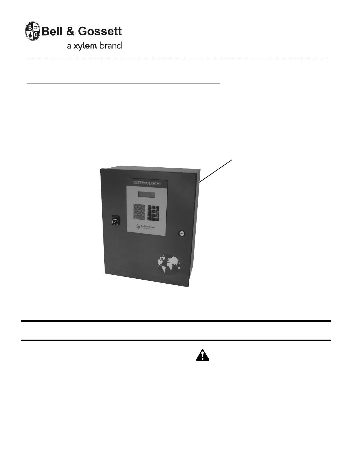
DESCRIPTION
Microprocessor based dedicated pump controller for variable
volume pumping systems. The control panel consists of the
following components: microprocessor, operator interface
with 4 line display and membrane key pad, and 24 VDC
power supply. Multi-pinned connecting cables for connection
to bypass panels are available as options.
OPERATIONAL LIMITS
See the control panel nameplate for operating voltage, current
draw, as well as information on the equipment to be connected to the control panel.
This safety alert symbol will be used in this manual and on the
Technologic 5500 Safety Instruction decal to draw attention to
safety related instructions. When used, the safety alert symbol
means ATTENTION! BECOME ALERT! YOUR SAFETY IS
INVOLVED! FAILURE TO FOLLOW THE INSTRUCTION
MAY RESULT IN A SAFETY HAZARD!
SAFETY
INSTRUCTIONS
Page 2

2
Preface
The following manual describes the new microprocessor based Technologic 5500 Variable Primary Pump
Controller. This unit is in the tradition of the other
members of the Technologic Control Panels as it
incorporates many original, novel, and proprietary features that may only be found on B&G controllers.
Some of these features require special emphasis here.
The controller is best described as a specific purpose
programmable pump and valve controller. This means
that the hardware and software have been created for
the control and diagnostics of pumps and valves with
consideration for their inherent characteristics. This
results in an optimum pump controller without the cost
of general purpose control hardware. Software is dedicated and established for the unit only after extensive
testing. Changes to this software are not taken lightly
and must pass rigid version control.
The controller has the unique analog input protection
of other members of the control family. In the event of
a short circuit condition the current limit circuitry prevents failure of the analog input components.
This new controller has standard manual motor bypass
switches when a Bell & Gossett automatic bypass is
supplied. The manual motor bypass switches allow
the user to de-energize the programmable logic controller and take manual control of the pumping system.
This is helpful during system startup to confirm pump
rotation and to purge air from the system prior to
switching to automatic control.
Page 3

3
SECTION 1 - GENERAL Page
1.1 Purpose of Manual . . . . . . . . . . . . . . . . . . . . . . . . . . . . . . . . . . . . . . . . . . . . . . . . . . . . . . . . . . . . .7
1.2 Safety . . . . . . . . . . . . . . . . . . . . . . . . . . . . . . . . . . . . . . . . . . . . . . . . . . . . . . . . . . . . . . . . . . . . .7
1.2.1 Safety Alert Symbol . . . . . . . . . . . . . . . . . . . . . . . . . . . . . . . . . . . . . . . . . . . . . . . . . . . . . . . . . .7
1.2.2 Safety Instruction Decal . . . . . . . . . . . . . . . . . . . . . . . . . . . . . . . . . . . . . . . . . . . . . . . . . . . . . . .7
1.2.3 Motor Safety . . . . . . . . . . . . . . . . . . . . . . . . . . . . . . . . . . . . . . . . . . . . . . . . . . . . . . . . . . . . . . . .7
1.2.4 Motor Control Equipment Safety . . . . . . . . . . . . . . . . . . . . . . . . . . . . . . . . . . . . . . . . . . . . . . . .7
1.3 Storage . . . . . . . . . . . . . . . . . . . . . . . . . . . . . . . . . . . . . . . . . . . . . . . . . . . . . . . . . . . . . . . . . . . . .7
1.4 Handling . . . . . . . . . . . . . . . . . . . . . . . . . . . . . . . . . . . . . . . . . . . . . . . . . . . . . . . . . . . . . . . . . . . . .7
1.5 Temperature and Ventilation . . . . . . . . . . . . . . . . . . . . . . . . . . . . . . . . . . . . . . . . . . . . . . . . . . . . . .7
1.6 Input Voltage . . . . . . . . . . . . . . . . . . . . . . . . . . . . . . . . . . . . . . . . . . . . . . . . . . . . . . . . . . . . . . . . . .7
1.7 Ground Connections . . . . . . . . . . . . . . . . . . . . . . . . . . . . . . . . . . . . . . . . . . . . . . . . . . . . . . . . . . . .7
1.8 Power Wiring . . . . . . . . . . . . . . . . . . . . . . . . . . . . . . . . . . . . . . . . . . . . . . . . . . . . . . . . . . . . . . . . . .8
1.9 Output/Motor Disconnect . . . . . . . . . . . . . . . . . . . . . . . . . . . . . . . . . . . . . . . . . . . . . . . . . . . . . . . .8
1.10 Analog Signal Wiring . . . . . . . . . . . . . . . . . . . . . . . . . . . . . . . . . . . . . . . . . . . . . . . . . . . . . . . . . . . .8
1.11 Field Connection Diagrams . . . . . . . . . . . . . . . . . . . . . . . . . . . . . . . . . . . . . . . . . . . . . . . . . . . . . . .8
1.12 Sensor and Control Wiring . . . . . . . . . . . . . . . . . . . . . . . . . . . . . . . . . . . . . . . . . . . . . . . . . . . . . . .8
1.12.1 DP Switches . . . . . . . . . . . . . . . . . . . . . . . . . . . . . . . . . . . . . . . . . . . . . . . . . . . . . . . . . . . . . . . .8
1.12.2 AFDs . . . . . . . . . . . . . . . . . . . . . . . . . . . . . . . . . . . . . . . . . . . . . . . . . . . . . . . . . . . . . . . . . . . . .8
1.12.3 Analog Inputs . . . . . . . . . . . . . . . . . . . . . . . . . . . . . . . . . . . . . . . . . . . . . . . . . . . . . . . . . . . . . . .9
1.12.4 Analog Inputs with External Power . . . . . . . . . . . . . . . . . . . . . . . . . . . . . . . . . . . . . . . . . . . . . .9
1.12.5 Drive Speed Signals . . . . . . . . . . . . . . . . . . . . . . . . . . . . . . . . . . . . . . . . . . . . . . . . . . . . . . . . . .9
1.12.6 Valve . . . . . . . . . . . . . . . . . . . . . . . . . . . . . . . . . . . . . . . . . . . . . . . . . . . . . . . . . . . . . . . . . . . . .9
1.12.7 Hardwire Communications . . . . . . . . . . . . . . . . . . . . . . . . . . . . . . . . . . . . . . . . . . . . . . . . . . . . .9
1.12.7.1 Remote Start/Stop . . . . . . . . . . . . . . . . . . . . . . . . . . . . . . . . . . . . . . . . . . . . . . . . . . . . . . . . .9
1.12.7.2 Remote Alarm Indication . . . . . . . . . . . . . . . . . . . . . . . . . . . . . . . . . . . . . . . . . . . . . . . . . . . .9
1.12.8 User Configurable I/O . . . . . . . . . . . . . . . . . . . . . . . . . . . . . . . . . . . . . . . . . . . . . . . . . . . . . . . . .9
SECTION 2 - INSTALLATION AND STARTUP
2.1 Location . . . . . . . . . . . . . . . . . . . . . . . . . . . . . . . . . . . . . . . . . . . . . . . . . . . . . . . . . . . . . . . . . . . . .9
2.2 Installation of Skid Mounted Systems with Factory Supplied Pumps . . . . . . . . . . . . . . . . . . . . . .9
2.2.1 Foundation . . . . . . . . . . . . . . . . . . . . . . . . . . . . . . . . . . . . . . . . . . . . . . . . . . . . . . . . . . . . . . . . .9
2.2.2 Grout . . . . . . . . . . . . . . . . . . . . . . . . . . . . . . . . . . . . . . . . . . . . . . . . . . . . . . . . . . . . . . . . . . . .10
2.2.3 Closed System Safety Measures . . . . . . . . . . . . . . . . . . . . . . . . . . . . . . . . . . . . . . . . . . . . . . .10
2.2.4 Eccentric Increasers . . . . . . . . . . . . . . . . . . . . . . . . . . . . . . . . . . . . . . . . . . . . . . . . . . . . . . . . .10
2.2.5 Pipe Support . . . . . . . . . . . . . . . . . . . . . . . . . . . . . . . . . . . . . . . . . . . . . . . . . . . . . . . . . . . . . .10
2.2.6 Expansion and Vibration Absorbtion . . . . . . . . . . . . . . . . . . . . . . . . . . . . . . . . . . . . . . . . . . . .10
2.2.7 Lubrication . . . . . . . . . . . . . . . . . . . . . . . . . . . . . . . . . . . . . . . . . . . . . . . . . . . . . . . . . . . . . . . .10
2.3 Putting the Unit into Service . . . . . . . . . . . . . . . . . . . . . . . . . . . . . . . . . . . . . . . . . . . . . . . . . . . . .10
2.3.1 Pump Rotation, 3 Phase Motors Only . . . . . . . . . . . . . . . . . . . . . . . . . . . . . . . . . . . . . . . . . . .10
2.3.2 Joint Check . . . . . . . . . . . . . . . . . . . . . . . . . . . . . . . . . . . . . . . . . . . . . . . . . . . . . . . . . . . . . . .10
SECTION 3 - OPERATOR INTERFACE
3.1 Power-Up . . . . . . . . . . . . . . . . . . . . . . . . . . . . . . . . . . . . . . . . . . . . . . . . . . . . . . . . . . . . . . . . . . .11
3.2 Technologic Pump Controller Screen . . . . . . . . . . . . . . . . . . . . . . . . . . . . . . . . . . . . . . . . . . . . . .11
3.3 Key Functionality . . . . . . . . . . . . . . . . . . . . . . . . . . . . . . . . . . . . . . . . . . . . . . . . . . . . . . . . . . . . . .11
3.4 LEDs . . . . . . . . . . . . . . . . . . . . . . . . . . . . . . . . . . . . . . . . . . . . . . . . . . . . . . . . . . . . . . . . . . . .11
SECTION 4 - SETUP SELECTION MENU
4.1 Sensors . . . . . . . . . . . . . . . . . . . . . . . . . . . . . . . . . . . . . . . . . . . . . . . . . . . . . . . . . . . . . . . . . . . .12
4.1.1 Sensor Number . . . . . . . . . . . . . . . . . . . . . . . . . . . . . . . . . . . . . . . . . . . . . . . . . . . . . . . . . . . .12
4.1.2 Edit/Copy . . . . . . . . . . . . . . . . . . . . . . . . . . . . . . . . . . . . . . . . . . . . . . . . . . . . . . . . . . . . . . . . .12
4.1.3 Sensor Edit . . . . . . . . . . . . . . . . . . . . . . . . . . . . . . . . . . . . . . . . . . . . . . . . . . . . . . . . . . . . . . . .12
4.1.4 Do Another . . . . . . . . . . . . . . . . . . . . . . . . . . . . . . . . . . . . . . . . . . . . . . . . . . . . . . . . . . . . . . . .12
4.1.5 Sensor Type . . . . . . . . . . . . . . . . . . . . . . . . . . . . . . . . . . . . . . . . . . . . . . . . . . . . . . . . . . . . . . .12
4.1.6 Sensor Span . . . . . . . . . . . . . . . . . . . . . . . . . . . . . . . . . . . . . . . . . . . . . . . . . . . . . . . . . . . . . . .12
4.1.7 Sensor Zero . . . . . . . . . . . . . . . . . . . . . . . . . . . . . . . . . . . . . . . . . . . . . . . . . . . . . . . . . . . . . . .13
4.1.8 Sensor PV . . . . . . . . . . . . . . . . . . . . . . . . . . . . . . . . . . . . . . . . . . . . . . . . . . . . . . . . . . . . . . . . .13
4.1.9 Sensor Set Point . . . . . . . . . . . . . . . . . . . . . . . . . . . . . . . . . . . . . . . . . . . . . . . . . . . . . . . . . . . .13
4.1.10 Sensor Override . . . . . . . . . . . . . . . . . . . . . . . . . . . . . . . . . . . . . . . . . . . . . . . . . . . . . . . . . . . .13
4.1.11 Sensor Setup Exit . . . . . . . . . . . . . . . . . . . . . . . . . . . . . . . . . . . . . . . . . . . . . . . . . . . . . . . . . . .13
4.1.12 Sensor Setup Exit (not PV) . . . . . . . . . . . . . . . . . . . . . . . . . . . . . . . . . . . . . . . . . . . . . . . . . . . .14
4.1.13 Copy Sensor . . . . . . . . . . . . . . . . . . . . . . . . . . . . . . . . . . . . . . . . . . . . . . . . . . . . . . . . . . . . . . .14
4.1.14 Chiller Sensor Span . . . . . . . . . . . . . . . . . . . . . . . . . . . . . . . . . . . . . . . . . . . . . . . . . . . . . . . . .14
4.1.15 Chiller Sensor Zero . . . . . . . . . . . . . . . . . . . . . . . . . . . . . . . . . . . . . . . . . . . . . . . . . . . . . . . . . .14
4.1.16 Chiller Number . . . . . . . . . . . . . . . . . . . . . . . . . . . . . . . . . . . . . . . . . . . . . . . . . . . . . . . . . . . . .14
4.1.17 Chiller Sensor Exit . . . . . . . . . . . . . . . . . . . . . . . . . . . . . . . . . . . . . . . . . . . . . . . . . . . . . . . . . .14
4.2 Pump Setup Menu . . . . . . . . . . . . . . . . . . . . . . . . . . . . . . . . . . . . . . . . . . . . . . . . . . . . . . . . . . . .14
4.2.1 Enable/Disable . . . . . . . . . . . . . . . . . . . . . . . . . . . . . . . . . . . . . . . . . . . . . . . . . . . . . . . . . . . . .14
Index
Page 4

4
INDEX (continued)
4.2.2 Number of Pumps . . . . . . . . . . . . . . . . . . . . . . . . . . . . . . . . . . . . . . . . . . . . . . . . . . . . . . . . . .15
4.2.3 Edit Pump . . . . . . . . . . . . . . . . . . . . . . . . . . . . . . . . . . . . . . . . . . . . . . . . . . . . . . . . . . . . . . . . .15
4.2.4 Edit Pump Number . . . . . . . . . . . . . . . . . . . . . . . . . . . . . . . . . . . . . . . . . . . . . . . . . . . . . . . . . .15
4.2.5 Enable/Disable Pump . . . . . . . . . . . . . . . . . . . . . . . . . . . . . . . . . . . . . . . . . . . . . . . . . . . . . . . .15
4.2.6 Do Another . . . . . . . . . . . . . . . . . . . . . . . . . . . . . . . . . . . . . . . . . . . . . . . . . . . . . . . . . . . . . . . .15
4.2.7 Pump Off Delay . . . . . . . . . . . . . . . . . . . . . . . . . . . . . . . . . . . . . . . . . . . . . . . . . . . . . . . . . . . .15
4.2.8 Lag Pump Run Timer . . . . . . . . . . . . . . . . . . . . . . . . . . . . . . . . . . . . . . . . . . . . . . . . . . . . . . . .15
4.2.9 Low Load Transfer . . . . . . . . . . . . . . . . . . . . . . . . . . . . . . . . . . . . . . . . . . . . . . . . . . . . . . . . . .16
4.2.10 High Low Transfer . . . . . . . . . . . . . . . . . . . . . . . . . . . . . . . . . . . . . . . . . . . . . . . . . . . . . . . . . .16
4.3 System Setup Menu . . . . . . . . . . . . . . . . . . . . . . . . . . . . . . . . . . . . . . . . . . . . . . . . . . . . . . . . . . .16
4.3.1 Stage/Destage Menu . . . . . . . . . . . . . . . . . . . . . . . . . . . . . . . . . . . . . . . . . . . . . . . . . . . . . . . .16
4.3.1.1 PV Stage . . . . . . . . . . . . . . . . . . . . . . . . . . . . . . . . . . . . . . . . . . . . . . . . . . . . . . . . . . . . . . .16
4.3.1.2 PV Destage . . . . . . . . . . . . . . . . . . . . . . . . . . . . . . . . . . . . . . . . . . . . . . . . . . . . . . . . . . . . .17
4.3.1.3 EOC Stage . . . . . . . . . . . . . . . . . . . . . . . . . . . . . . . . . . . . . . . . . . . . . . . . . . . . . . . . . . . . . .17
4.3.1.4 EOC Destage . . . . . . . . . . . . . . . . . . . . . . . . . . . . . . . . . . . . . . . . . . . . . . . . . . . . . . . . . . . .18
4.3.2 PID Setup Menu . . . . . . . . . . . . . . . . . . . . . . . . . . . . . . . . . . . . . . . . . . . . . . . . . . . . . . . . . . . .18
4.3.3 Alarms Setup . . . . . . . . . . . . . . . . . . . . . . . . . . . . . . . . . . . . . . . . . . . . . . . . . . . . . . . . . . . . . .18
4.3.4 Alternation Setup . . . . . . . . . . . . . . . . . . . . . . . . . . . . . . . . . . . . . . . . . . . . . . . . . . . . . . . . . . .18
4.3.5 Bypass Setup . . . . . . . . . . . . . . . . . . . . . . . . . . . . . . . . . . . . . . . . . . . . . . . . . . . . . . . . . . . . . .19
4.3.6 AFD Setup . . . . . . . . . . . . . . . . . . . . . . . . . . . . . . . . . . . . . . . . . . . . . . . . . . . . . . . . . . . . . . . .19
4.3.7 Date/Time Setup . . . . . . . . . . . . . . . . . . . . . . . . . . . . . . . . . . . . . . . . . . . . . . . . . . . . . . . . . . . .19
4.3.8 Password Setup . . . . . . . . . . . . . . . . . . . . . . . . . . . . . . . . . . . . . . . . . . . . . . . . . . . . . . . . . . . .20
4.3.9 I/O Setup . . . . . . . . . . . . . . . . . . . . . . . . . . . . . . . . . . . . . . . . . . . . . . . . . . . . . . . . . . . . . . . . .20
4.3.9.1 DI . . . . . . . . . . . . . . . . . . . . . . . . . . . . . . . . . . . . . . . . . . . . . . . . . . . . . . . . . . . . . . . . . . . .20
4.3.9.2 DO . . . . . . . . . . . . . . . . . . . . . . . . . . . . . . . . . . . . . . . . . . . . . . . . . . . . . . . . . . . . . . . . . . . .21
4.3.9.3 AI . . . . . . . . . . . . . . . . . . . . . . . . . . . . . . . . . . . . . . . . . . . . . . . . . . . . . . . . . . . . . . . . . . . .21
4.3.9.4 AO . . . . . . . . . . . . . . . . . . . . . . . . . . . . . . . . . . . . . . . . . . . . . . . . . . . . . . . . . . . . . . . . . . . .21
4.3.10 Communication Setup Menu . . . . . . . . . . . . . . . . . . . . . . . . . . . . . . . . . . . . . . . . . . . . . . . . . .22
4.3.10.1 BACnet . . . . . . . . . . . . . . . . . . . . . . . . . . . . . . . . . . . . . . . . . . . . . . . . . . . . . . . . . . . . . . . .22
4.3.10.2 Metasys N2 . . . . . . . . . . . . . . . . . . . . . . . . . . . . . . . . . . . . . . . . . . . . . . . . . . . . . . . . . . . . .22
4.3.10.3 Modbus . . . . . . . . . . . . . . . . . . . . . . . . . . . . . . . . . . . . . . . . . . . . . . . . . . . . . . . . . . . . . . . .22
4.3.10.4 BACnet/IP . . . . . . . . . . . . . . . . . . . . . . . . . . . . . . . . . . . . . . . . . . . . . . . . . . . . . . . . . . . . . .23
4.3.11 Special Functions . . . . . . . . . . . . . . . . . . . . . . . . . . . . . . . . . . . . . . . . . . . . . . . . . . . . . . . . . . .23
4.3.12 Brightness/Contrast . . . . . . . . . . . . . . . . . . . . . . . . . . . . . . . . . . . . . . . . . . . . . . . . . . . . . . . . .23
4.3.13 Save to Flash . . . . . . . . . . . . . . . . . . . . . . . . . . . . . . . . . . . . . . . . . . . . . . . . . . . . . . . . . . . . . .23
4.3.14 Load from Flash . . . . . . . . . . . . . . . . . . . . . . . . . . . . . . . . . . . . . . . . . . . . . . . . . . . . . . . . . . . .24
4.4 Test Selection Menu . . . . . . . . . . . . . . . . . . . . . . . . . . . . . . . . . . . . . . . . . . . . . . . . . . . . . . . . . . .24
4.4.1 DI Test . . . . . . . . . . . . . . . . . . . . . . . . . . . . . . . . . . . . . . . . . . . . . . . . . . . . . . . . . . . . . . . . . . .24
4.4.2 DO Test . . . . . . . . . . . . . . . . . . . . . . . . . . . . . . . . . . . . . . . . . . . . . . . . . . . . . . . . . . . . . . . . . .24
4.4.3 AI Test . . . . . . . . . . . . . . . . . . . . . . . . . . . . . . . . . . . . . . . . . . . . . . . . . . . . . . . . . . . . . . . . . . .24
4.4.4 AO Test . . . . . . . . . . . . . . . . . . . . . . . . . . . . . . . . . . . . . . . . . . . . . . . . . . . . . . . . . . . . . . . . . . .24
4.4.5 LED Test . . . . . . . . . . . . . . . . . . . . . . . . . . . . . . . . . . . . . . . . . . . . . . . . . . . . . . . . . . . . . . . . . .24
4.4.6 Key Test . . . . . . . . . . . . . . . . . . . . . . . . . . . . . . . . . . . . . . . . . . . . . . . . . . . . . . . . . . . . . . . . . .24
4.4.7 Disp Test . . . . . . . . . . . . . . . . . . . . . . . . . . . . . . . . . . . . . . . . . . . . . . . . . . . . . . . . . . . . . . . . .25
4.4.8 Comm Test . . . . . . . . . . . . . . . . . . . . . . . . . . . . . . . . . . . . . . . . . . . . . . . . . . . . . . . . . . . . . . . .25
4.5 Default Setup . . . . . . . . . . . . . . . . . . . . . . . . . . . . . . . . . . . . . . . . . . . . . . . . . . . . . . . . . . . . . . . . .25
4.6 Chiller Setup . . . . . . . . . . . . . . . . . . . . . . . . . . . . . . . . . . . . . . . . . . . . . . . . . . . . . . . . . . . . . . . . .25
4.6.1 Enbl/Disbl Chiller . . . . . . . . . . . . . . . . . . . . . . . . . . . . . . . . . . . . . . . . . . . . . . . . . . . . . . . . . . .25
4.6.2 Chiller's Run Tmr . . . . . . . . . . . . . . . . . . . . . . . . . . . . . . . . . . . . . . . . . . . . . . . . . . . . . . . . . . .26
4.6.3 Isolation Valve . . . . . . . . . . . . . . . . . . . . . . . . . . . . . . . . . . . . . . . . . . . . . . . . . . . . . . . . . . . . .26
4.7 Bypass Valve Setup . . . . . . . . . . . . . . . . . . . . . . . . . . . . . . . . . . . . . . . . . . . . . . . . . . . . . . . . . . .27
4.7.1 Bypass Valve Setting . . . . . . . . . . . . . . . . . . . . . . . . . . . . . . . . . . . . . . . . . . . . . . . . . . . . . . . .27
4.7.2 Bypass Operation Mode . . . . . . . . . . . . . . . . . . . . . . . . . . . . . . . . . . . . . . . . . . . . . . . . . . . . . .27
4.7.3 Timers . . . . . . . . . . . . . . . . . . . . . . . . . . . . . . . . . . . . . . . . . . . . . . . . . . . . . . . . . . . . . . . . . . . .27
SECTION 5 - OPERATION
5.1 Status Screens . . . . . . . . . . . . . . . . . . . . . . . . . . . . . . . . . . . . . . . . . . . . . . . . . . . . . . . . . . . . . . .28
5.1.1 Technologic Pump Controller Screen . . . . . . . . . . . . . . . . . . . . . . . . . . . . . . . . . . . . . . . . . . .28
5.1.2 Pump Status Screen . . . . . . . . . . . . . . . . . . . . . . . . . . . . . . . . . . . . . . . . . . . . . . . . . . . . . . . .28
5.1.3 Pump Speed Screen . . . . . . . . . . . . . . . . . . . . . . . . . . . . . . . . . . . . . . . . . . . . . . . . . . . . . . . .28
5.1.4 Chiller Status Screen . . . . . . . . . . . . . . . . . . . . . . . . . . . . . . . . . . . . . . . . . . . . . . . . . . . . . . . .28
5.1.5 Chiller Data Screen . . . . . . . . . . . . . . . . . . . . . . . . . . . . . . . . . . . . . . . . . . . . . . . . . . . . . . . . . .28
5.1.6 Active Values Data Screen . . . . . . . . . . . . . . . . . . . . . . . . . . . . . . . . . . . . . . . . . . . . . . . . . . . .28
5.1.7 Bypass Valve Signal Screen . . . . . . . . . . . . . . . . . . . . . . . . . . . . . . . . . . . . . . . . . . . . . . . . . . .28
5.1.8 Manual Speed Screen . . . . . . . . . . . . . . . . . . . . . . . . . . . . . . . . . . . . . . . . . . . . . . . . . . . . . . .28
5.1.9 Active Values Seq Screen . . . . . . . . . . . . . . . . . . . . . . . . . . . . . . . . . . . . . . . . . . . . . . . . . . . .29
5.1.10 Bypass Valve Position Screen . . . . . . . . . . . . . . . . . . . . . . . . . . . . . . . . . . . . . . . . . . . . . . . . .29
5.1.11 Sys. Temp Screen . . . . . . . . . . . . . . . . . . . . . . . . . . . . . . . . . . . . . . . . . . . . . . . . . . . . . . . . . .29
5.1.12 Isolation Valve Status Screen . . . . . . . . . . . . . . . . . . . . . . . . . . . . . . . . . . . . . . . . . . . . . . . . . .29
Page 5

5
INDEX (continued)
5.2 Bypass Valve Operation . . . . . . . . . . . . . . . . . . . . . . . . . . . . . . . . . . . . . . . . . . . . . . . . . . . . . . . .29
5.2.1 Manual Bypass Valve Operation . . . . . . . . . . . . . . . . . . . . . . . . . . . . . . . . . . . . . . . . . . . . . . .29
5.2.2 Auto Bypass Valve Operation . . . . . . . . . . . . . . . . . . . . . . . . . . . . . . . . . . . . . . . . . . . . . . . . . .29
5.3 Manual Bypass Operation . . . . . . . . . . . . . . . . . . . . . . . . . . . . . . . . . . . . . . . . . . . . . . . . . . . . . . .29
5.4 Hand Manual Operation . . . . . . . . . . . . . . . . . . . . . . . . . . . . . . . . . . . . . . . . . . . . . . . . . . . . . . . .30
5.5 Hand Bypass Operation . . . . . . . . . . . . . . . . . . . . . . . . . . . . . . . . . . . . . . . . . . . . . . . . . . . . . . . .30
5.6 Setpoint Modification . . . . . . . . . . . . . . . . . . . . . . . . . . . . . . . . . . . . . . . . . . . . . . . . . . . . . . . . . .30
5.7 Process Variable Monitoring . . . . . . . . . . . . . . . . . . . . . . . . . . . . . . . . . . . . . . . . . . . . . . . . . . . . .30
5.8 Request to Stage/Destage Chillers . . . . . . . . . . . . . . . . . . . . . . . . . . . . . . . . . . . . . . . . . . . . . . . .30
5.9 Alternation . . . . . . . . . . . . . . . . . . . . . . . . . . . . . . . . . . . . . . . . . . . . . . . . . . . . . . . . . . . . . . . . . . .31
5.10 Alarms . . . . . . . . . . . . . . . . . . . . . . . . . . . . . . . . . . . . . . . . . . . . . . . . . . . . . . . . . . . . . . . . . . . .31
SECTION 6 - MAINTENANCE
6.1 Technical Overview . . . . . . . . . . . . . . . . . . . . . . . . . . . . . . . . . . . . . . . . . . . . . . . . . . . . . . . . . . . .32
6.2 Digital Inputs . . . . . . . . . . . . . . . . . . . . . . . . . . . . . . . . . . . . . . . . . . . . . . . . . . . . . . . . . . . . . . . . .32
6.3 Digital Outputs . . . . . . . . . . . . . . . . . . . . . . . . . . . . . . . . . . . . . . . . . . . . . . . . . . . . . . . . . . . . . . .32
6.4 Analog Inputs . . . . . . . . . . . . . . . . . . . . . . . . . . . . . . . . . . . . . . . . . . . . . . . . . . . . . . . . . . . . . . . .32
6.5 Memory . . . . . . . . . . . . . . . . . . . . . . . . . . . . . . . . . . . . . . . . . . . . . . . . . . . . . . . . . . . . . . . . . . . .32
6.6 CPU . . . . . . . . . . . . . . . . . . . . . . . . . . . . . . . . . . . . . . . . . . . . . . . . . . . . . . . . . . . . . . . . . . . .32
6.7 Power Supply . . . . . . . . . . . . . . . . . . . . . . . . . . . . . . . . . . . . . . . . . . . . . . . . . . . . . . . . . . . . . . . .32
6.8 Protection . . . . . . . . . . . . . . . . . . . . . . . . . . . . . . . . . . . . . . . . . . . . . . . . . . . . . . . . . . . . . . . . . . .32
6.9 Instruments and their Use . . . . . . . . . . . . . . . . . . . . . . . . . . . . . . . . . . . . . . . . . . . . . . . . . . . . . . .32
6.9.1 AC/DC Voltmeter . . . . . . . . . . . . . . . . . . . . . . . . . . . . . . . . . . . . . . . . . . . . . . . . . . . . . . . . . . .32
6.9.2 Ohmmeter . . . . . . . . . . . . . . . . . . . . . . . . . . . . . . . . . . . . . . . . . . . . . . . . . . . . . . . . . . . . . . . . .32
6.9.3 Milliamp Meter . . . . . . . . . . . . . . . . . . . . . . . . . . . . . . . . . . . . . . . . . . . . . . . . . . . . . . . . . . . . .32
6.9.4 Signal Generator (analyzer) - recommended . . . . . . . . . . . . . . . . . . . . . . . . . . . . . . . . . . . . . .32
6.10 Field Repair . . . . . . . . . . . . . . . . . . . . . . . . . . . . . . . . . . . . . . . . . . . . . . . . . . . . . . . . . . . . . . . . . .33
6.11 Program Updating . . . . . . . . . . . . . . . . . . . . . . . . . . . . . . . . . . . . . . . . . . . . . . . . . . . . . . . . . . . . .33
6.12 Controller Information Screen . . . . . . . . . . . . . . . . . . . . . . . . . . . . . . . . . . . . . . . . . . . . . . . . . . . .33
6.13 Logging . . . . . . . . . . . . . . . . . . . . . . . . . . . . . . . . . . . . . . . . . . . . . . . . . . . . . . . . . . . . . . . . . . . .33
6.13.1 Alarm Log . . . . . . . . . . . . . . . . . . . . . . . . . . . . . . . . . . . . . . . . . . . . . . . . . . . . . . . . . . . . . .33
6.13.2 Pump Log . . . . . . . . . . . . . . . . . . . . . . . . . . . . . . . . . . . . . . . . . . . . . . . . . . . . . . . . . . . . . .33
6.13.2.1 Pump Run Time Log . . . . . . . . . . . . . . . . . . . . . . . . . . . . . . . . . . . . . . . . . . . . . . . . . . . .33
6.13.2.2 Pump On/Off Log . . . . . . . . . . . . . . . . . . . . . . . . . . . . . . . . . . . . . . . . . . . . . . . . . . . . . .33
6.13.3 Data Log Menu . . . . . . . . . . . . . . . . . . . . . . . . . . . . . . . . . . . . . . . . . . . . . . . . . . . . . . . . . .34
6.13.3.1 PV Log . . . . . . . . . . . . . . . . . . . . . . . . . . . . . . . . . . . . . . . . . . . . . . . . . . . . . . . . . . . . . .34
6.13.3.2 KWH Log . . . . . . . . . . . . . . . . . . . . . . . . . . . . . . . . . . . . . . . . . . . . . . . . . . . . . . . . . . . . .34
6.13.3.3 Flow Log . . . . . . . . . . . . . . . . . . . . . . . . . . . . . . . . . . . . . . . . . . . . . . . . . . . . . . . . . . . . .34
6.13.4 Operation Log Menu . . . . . . . . . . . . . . . . . . . . . . . . . . . . . . . . . . . . . . . . . . . . . . . . . . . . . .34
6.13.4.1 System On/Off Log . . . . . . . . . . . . . . . . . . . . . . . . . . . . . . . . . . . . . . . . . . . . . . . . . . . . .34
6.13.4.2 Op Mode Changes Log . . . . . . . . . . . . . . . . . . . . . . . . . . . . . . . . . . . . . . . . . . . . . . . . .34
6.13.4.3 Alternations Log . . . . . . . . . . . . . . . . . . . . . . . . . . . . . . . . . . . . . . . . . . . . . . . . . . . . . . .34
6.13.4.4 System Reset Log . . . . . . . . . . . . . . . . . . . . . . . . . . . . . . . . . . . . . . . . . . . . . . . . . . . . . .35
6.13.4.5 Control Logger . . . . . . . . . . . . . . . . . . . . . . . . . . . . . . . . . . . . . . . . . . . . . . . . . . . . . . . .35
6.13.5 Power Log . . . . . . . . . . . . . . . . . . . . . . . . . . . . . . . . . . . . . . . . . . . . . . . . . . . . . . . . . . . . . .35
6.13.6 Service Log Menu . . . . . . . . . . . . . . . . . . . . . . . . . . . . . . . . . . . . . . . . . . . . . . . . . . . . . . . .35
6.13.6.1 Error Log . . . . . . . . . . . . . . . . . . . . . . . . . . . . . . . . . . . . . . . . . . . . . . . . . . . . . . . . . . . . .35
6.13.6.2 Operating Hours Log . . . . . . . . . . . . . . . . . . . . . . . . . . . . . . . . . . . . . . . . . . . . . . . . . . .35
6.14 Maintenance (Physical) . . . . . . . . . . . . . . . . . . . . . . . . . . . . . . . . . . . . . . . . . . . . . . . . . . . . . . .35
6.14.1 Electrical . . . . . . . . . . . . . . . . . . . . . . . . . . . . . . . . . . . . . . . . . . . . . . . . . . . . . . . . . . . . . . .35
6.14.2 Mechanical . . . . . . . . . . . . . . . . . . . . . . . . . . . . . . . . . . . . . . . . . . . . . . . . . . . . . . . . . . . . .35
APPENDIX A System Check List – Mechanical . . . . . . . . . . . . . . . . . . . . . . . . . . . . . . . . . . . . . . . . . . . .36
APPENDIX B System Check List – Electrical . . . . . . . . . . . . . . . . . . . . . . . . . . . . . . . . . . . . . . . . . . . . .36
APPENDIX C Valid I/O Codes . . . . . . . . . . . . . . . . . . . . . . . . . . . . . . . . . . . . . . . . . . . . . . . . . . . . . . . . .37
APPENDIX D BACnet MS/TP Protocol Implementation Conformance Statement . . . . . . . . . . . . . . . . .38
APPENDIX E BACnet IP Protocol Implementation Conformance Statement . . . . . . . . . . . . . . . . . . . . .39
APPENDIX F BACnet Communications Objects . . . . . . . . . . . . . . . . . . . . . . . . . . . . . . . . . . . . . . . .40-42
APPENDIX G LonWorks Communications Points . . . . . . . . . . . . . . . . . . . . . . . . . . . . . . . . . . . . . . .43-46
APPENDIX H Metasys N2 Communications Points . . . . . . . . . . . . . . . . . . . . . . . . . . . . . . . . . . . . . .47-49
APPENDIX I Modbus Communications Points . . . . . . . . . . . . . . . . . . . . . . . . . . . . . . . . . . . . . . . . .50-52
APPENDIX J Drawings . . . . . . . . . . . . . . . . . . . . . . . . . . . . . . . . . . . . . . . . . . . . . . . . . . . . . . . . . . . .53-54
Page 6

6
NOTE: The information contained in this manual is intended to assist operating personnel by providing information on the char-
acteristics of the purchased equipment.
It does not relieve the user of the responsibility to adhere to local codes and ordinances and the use of accepted practices in
the installation, operation and maintenance of this equipment.
Further information pertaining to the installation, operation, and maintenance of your Technologic 5500 series pump controller
can be found in the I.O.M.s for the associated equipment provided see Section 5, Maintenance, for a list of relevant manuals.
Glossary of Terms
AFD
Adjustable Frequency Drive; converts a constant power input
into a variable power output for the motor; a device for controlling motor speed
Alternation
Process of determining which pump will serve as lead pump
and which pump will serve as lag pump
Bypass
Controller bypasses the AFD, pumps stop running in variable
speed mode and run at constant speed (50 Hz / 60 Hz)
Bypass Valve
Modulating valve that controls the minimum flow required by
chillers
Destage
To turn off a lag pump
EOC
End of Curve; point at which a pump is staged or destaged
I.O.M.
Installation Operation Manual
Isolation Valve
Two way control valve that isolates flow from standby chillers
Lag pump
Standby pump that activates only when lead pump alone
cannot efficiently provide sufficient pressure or flow rate
Lead pump
Duty pump which runs continuously until a standby pump is
required
LED
Light emitting diode, located on OIP and controller
OIP
Operator Interface Panel
O.L.
Overload: device to protect a motor from overheating
PID
Proportional Integral Derivative; 3 variables required for error
control
Process Variable
Signal generated by a sensor that is set up to control the
system
Proof timer
Minimum time period before controller acknowledges an
input; time period for which a signal must be stable before it
is accepted by the controller as a sustained and valid signal
RTC
Real time clock
RTD
Resistive temperature device used to supply temperature
signals to the PLC
Stage
To start a lag pump
Page 7
7
1.1
Purpose of Manual
This manual is furnished to acquaint you with some
of the practical ways to install, operate, and maintain
this unit. Read it carefully before doing any work on
your unit and keep it handy for future reference.
Equipment cannot operate well without proper care.
To keep this unit at top efficiency, follow the recommended installation and servicing procedures outlined in this manual.
1.2
Safety
1.2.1 Safety Alert Symbol
SAFETY INSTRUCTION
This safely alert symbol will be used in this manual
and on the unit safety instruction to draw attention to
safety related instructions. When used the safety alert
symbol means
ATTENTION BECOME ALERT!
YOUR SAFETY IS INVOLVED! FAILURE TO FOLLOW THIS INSTRUCTION MAY RESULT IN A
SAFETY HAZARD.
1.2.2 Safety Instruction Decal
Your Technologic 5500 Series Variable Primary Pump
and Valve Controller should have a safety instruction
decal (part # S11550). If the decal is missing or
illegible contact your local B&G representative for a
replacement.
1.2.3
Motor Safety
Each motor must have a properly sized starter with
properly sized overload block to provide overload
and undervoltage protection. Ground fault protection
should be sized properly. Refer to local electrical
codes for sizing and selection. Refer to the motor
manufacturer's I.O.M. (Installation Operation Manual)
for specific installation information. Even when the
motor is stopped, it should be considered "alive" as
long as its controller is energized.
The use of motor disconnect switches is acceptable.
Consult the factory for proper interlocking with
adjustable frequency drives, AFD's. See section 1.9.
1.2.4
Motor Control Equipment Safety
Motor control equipment and electronic controls are
connected to hazardous line voltages. When servicing electronic controls, there will be exposed components at or above line potential. Extreme care should
be taken to protect against shock. Stand on an insulating pad and make it a habit to use only one hand
when checking components. Always use accurate
test meters when checking electrical components.
Always work with another person in case of an emergency. Disconnect power when performing maintenance. Be sure equipment is properly grounded.
Wear safety glasses whenever working on electronic
control or rotating equipment.
1.3
Storage
For long periods of storage, the unit should be cov-
ered to prevent corrosion and contamination from
dirt. It should be STORED in a clean, dry location
between -20 and +60ºC. The relative humidity
should not exceed 85%. The unit should be checked
periodically to ensure that no condensation has
formed. After storage, again check that it is dry
before applying power.
NOTE: EXTENDED STORAGE OF AFDs MAY
REQUIRE SPECIAL ATTENTION PRIOR TO STARTUP. SEE MANUFACTURER'S I.O.M. FOR DETAILS.
1.4
Handling
Care should be taken to prevent damage due to
dropping or jolting when moving the Technologic Variable Primary Pump and Valve Controller. Transportation damage should be brought to the carrier's attention immediately upon receipt.
1.5
Temperature and Ventilation
All electrical equipment is susceptible to failure if
operated in ambient temperatures outside of its rating. The operating temperature range for this unit is
0 to 40°C. The relative humidity should not exceed
95% non-condensing. The unit should not be operated outside these extremes.
1.6
Input Voltage
The Technologic Variable Primary Pump and Valve
Controller was factory set to operate on the voltage
shown on the nameplate. Check the AFD nameplate
for the proper input and output voltages before wiring
the AFD.
The voltage tolerance is +10/-5% and phase to
phase voltage must not have an imbalance greater
than 5 VAC.
Section 1 - General
DANGER: Troubleshooting live control panels exposes
personnel to hazardous voltages. Only a qualified elec-
trician may do electrical troubleshooting.
FAILURE TO FOL-
LOW THESE INSTRUCTIONS MAY RESULT IN SERIOUS
PERSONAL INJURY, DEATH, AND/OR PROPERTY
DAMAGE.
WARNING: Motor can start automatically. Keep
hands away from output shaft until motor is completely stopped and input power is removed from the motor
control panel. Lockout main power switch while working
near the motor shaft.
FAILURE TO FOLLOW THESE
INSTRUCTIONS COULD RESULT IN SERIOUS PERSONAL INJURY, DEATH, AND/OR PROPERTY DAMAGE.
WARNING: Prevent electrical shocks. Disconnect
the power supply before beginning installation.
FAIL-
URE TO FOLLOW THESE INSTRUCTIONS COULD
RESULT IN SERIOUS PERSONAL INJURY, DEATH,
AND/OR PROPERTY DAMAGE.
Page 8
8
1.7
Ground Connections
A grounding terminal is provided for a dedicated
ground wire connection. All provisions of the
National Electrical Code and local codes must be
followed.
1.8
Power Wiring
Power wire types and sizes must be selected based
upon conformance with the National Electrical Code
and all local codes and restrictions. In addition, only
copper (Cu) wire rated for 75°C (minimum) may be
used for the power connections. Refer to the input
current as listed on the nameplate on the enclosure
door when sizing wire.
1.9
Output/Motor Disconnect
It is necessary that any device that can disconnect
the motor from the output of the AFD be interlocked
to the emergency shutdown circuits of the AFD. This
will provide an orderly shutdown if the disconnecting
device is open circuited while the AFD is in operation.
Failure to provide this interlock may result in damaged components due to improper installation.
1.10
Analog Signal Wiring
Shielded cable (#22 AWG, Belden type 8762, Alpha
#2411, or equal) should be installed for all D.C. control wiring. The shield must be terminated in the
Technologic Variable Primary Pump and Valve
Controller panel.
Do not connect the shield at the
other end of the cable! Insulate the shield so that
no electrical connection is made at the other end
of the cable.
A twisted pair of #22 AWG conductors
(Belden 8442 or equal) can be used in place of
shielded cable. The cable length must be limited to
5,000 feet for #22 AWG wire.
1.11 Field Connection Diagrams
Refer to the pump I.O.M. for specific details unique to
the pump.
Refer to the flow sensor/transmitter I.O.M. for specific
details unique to the flow sensor/transmitter.
The Wiring Diagram(s), Dimensional Drawings and
Field Connection Diagram should be reviewed prior
to unit installation and operation.
1.12
Sensor and Control Wiring
The following sections are based on the installation of
standard Technologic 5500 product. Because customized software and hardware is available, the
installing contractor should base all wiring connections on the wiring diagrams that accompany each
controller. These sections are meant to complement,
not replace, those wiring diagrams.
1.12.1
DP Switches
Differential pressure switches sense the increase in
pressure between the pump suction and discharge
gauge taps. DP switches are used to determine
whether a pump is running. Each switch should be
wired from the normally closed contact.
1.12.2
AFDs
To monitor if an adjustable frequency drive is running,
it is necessary to wire from each AFD's normally
open "run" or "on" contact.
For the Technologic Variable Primary Pump and
Valve Controller to start and stop each AFD, it is necessary to wire to the remote start terminals in each
AFD.
Additional wiring to each of the adjustable frequency
drives may be required with certain types of controller programs. Refer to the wiring diagram for all
connection points.
With certain bypass and control methods, it is necessary to disable an adjustable frequency drive from
running. This is accomplished by wiring from the
Technologic 5500 terminals to each AFD's interlock
terminals. Should this wiring be required, any
jumpers which may be found on the AFD's interlock
terminals should be removed.
1.12.3
Analog Inputs
The Technologic 5500 control family has the capa-
bility to accept many analog inputs. Typically, all
analog inputs must be 4-20mA and powered by the
24VDC power supply in the Technologic 5500. All
shields must be grounded, only in the Technologic
5500, to prevent ground loops and improper signals.
To monitor system zones, it is not necessary for all
analog inputs to be used. It is necessary, however,
that all zone transmitters be connected consecutively
starting with zone 1. Optional transmitters (i.e., other
than zones) may be supplied.
CAUTION: Metal filings can create electrical short
circuits. Do not drill, saw, file or perform any operation on the AFD conduit entry plate while attached to the
AFD.
FAILURE TO FOLLOW THESE INSTRUCTIONS
COULD RESULT IN PROPERTY DAMAGE AND/OR
MODERATE PERSONAL INJURY.
WARNING: Conduit grounds are not adequate. A
separate ground wire must be attached to the ground
lug provided in the enclosure to avoid potential safety hazards.
FAILURE TO FOLLOW THESE INSTRUCTIONS
COULD RESULT IN SERIOUS PERSONAL INJURY,
DEATH, AND/OR PROPERTY DAMAGE.
WARNING: Prevent electrical shocks. Disconnect
the power supply before beginning installation.
FAIL-
URE TO FOLLOW THESE INSTRUCTIONS COULD
RESULT IN SERIOUS PERSONAL INJURY, DEATH,
AND/OR PROPERTY DAMAGE.
Page 9
9
1.12.4
Analog Inputs with External Power
The following steps describe the general procedure
for rewiring an analog input sensor when the sensor's
power source is not the Technologic 5500 controller.
1) Turn off all power to the Technologic 5500 controller.
2) Refer to the appropriate controller wiring diagram
that was shipped with unit. Locate the analog
input sensors on the wiring diagram that will be
rewired. They are labeled AI X.
3) Remove the 24 VDC positive (+) wire from TB 40
for the respective analog input sensor connection.
This wire needs to be removed completely or terminated if used as a jumper. This will prevent any
accidental contact with a negative (-) voltage
source (i.e. control panel) and avoid becoming a
short circuit. Care should be taken to ensure that
24 VDC positive (+) voltage is still provided to any
remaining sensors that will be powered by the
Technologic 5500 controller.
4) Remove the 24 VDC negative (-) wire from TB 41
for the respective analog input sensor connection.
This wire needs to be removed completely or terminated if used as a jumper. This will prevent any
accidental contact with a positive (+) voltage
source and avoid becoming a short circuit. Care
should be taken to ensure that 24 VDC (-) negative
voltage is still provided to any remaining sensors
that will still be powered by the Technologic 5500
controller.
5) Terminate the negative (-) wire of the sensor to TB
41 of the respective analog input sensor connection. Terminate the positive (+) wire of the sensor
to the terminal block which is connected to the
positive (+) terminal shown on the Analog input
card.
NOTE: Be certain that the power supplied to other
terminal blocks has not been interrupted! The wires
that were removed in the preceding steps may have
been used as jumpers.
1.12.5 Drive Speed Signals
Drive speed (follower) signals must be wired from the
Technologic 5500 Controller to each of the adjustable
frequency drives. The AFDs must be configured to
accept a 0-10 VDC speed signal with the minimum
speed set for 30% (0 VDC) and maximum speed set
for 100% (10 VDC). All shields must be grounded,
only in the Technologic 5500, to prevent ground
loops and improper signals.
1.12.6
Valve
The Valve must be configured to accept a 4 - 20mA
signal with the closed position set for 4 mA and the
open position set for 20 mA. All shields must be
grounded, only in the Technologic 5500, to prevent
ground loops and improper signals.
1.12.7
Hardwire Communications
Hardwire communications refers to the capability of
the Technologic 5500 Controller to communicate with
an energy management system. Standard communication features such as remote start/stop and remote
alarm indications are listed below.
1.12.7.1
Remote Start/Stop
Install a switch as indicated on the wiring diagram.
With the LOCAL-REMOTE-OFF switch in the
REMOTE position, this contact closure will provide
the start signal.
1.12.7.2
Remote Alarm Indication
A digital output rated 8 amps at 115V is supplied.
This output closes to indicate an alarm condition
exists.
1.12.8
User Configurable I/O
The Technologic 5500 Controller comes equipped
with the capability to define the operation of any
unused input or output signal. Refer to Section 4.3.9
for detailed information on the I/O Setup Menu.
WARNING: Prevent electrical shocks. Disconnect
the power supply before beginning installation.
FAIL-
URE TO FOLLOW THESE INSTRUCTIONS COULD
RESULT IN SERIOUS PERSONAL INJURY, DEATH,
AND/OR PROPERTY DAMAGE.
Section 2 - Installation and Startup
2.1 Location
Install the pumping unit appropriately for ease of
inspection, maintenance and service. Observe local
electrical codes concerning control panel spacing.
2.2
Installation of Skid Mounted Systems with
Factory Supplied Pumps
This unit is built to give you years of service if it is
installed properly with a suitable foundation.
2.2.1
Foundation
A base of concrete weighing 2-1/2 times the weight
of the unit is recommended. Check the shipping
ticket for unit weight. Tie the concrete pad in with
the finished floor. Use foundation bolts and larger
pipe sleeves to give room for final bolt location.
Place the unit on its concrete foundation, supporting
it with steel wedges or shims totaling 1" in thickness.
These wedges or shims should be put on both sides
of each anchor-bolt to provide a means of leveling
the base.
DANGER: Heavy load, may drop if not lifted properly.
Do not lift the entire unit by the motor eyebolts. Lift
the unit with slings placed under the unit base rails.
FAIL-
URE TO FOLLOW THESE INSTRUCTIONS COULD
RESULT IN SERIOUS PERSONAL INJURY, DEATH,
AND/OR PROPERTY DAMAGE.
Page 10
10
2.2.2
Grout
After the frame has been leveled and securely bolted
to the pad, a good grade of grout should be installed
beneath the base. A suggested mixture for grout is:
one part Portland Cement and two or three parts
plain, sharp sand mixed with water until it will pour
easily. Commercial grout mixtures with suspended
iron particles are available. Wet the concrete base
before pouring grout. To hold wedges or shims in
place, allow the grout to flow around them and
beneath the entire length of the base flange.
2.2.3
Closed System Safety Measures
Important:
Do not install and operate the Bell &
Gossett Technologic 5500 Variable Primary pump
and valve controller in a closed system unless the
system is constructed with properly sized safety and
control devices. Such devices include the use of
properly sized and located pressure relief valves,
compression tanks, pressure controls, temperature
controls and flow controls as appropriate. If the system does not include these devices, consult the
responsible engineer or architect before making
pumps operational.
2.2.4 Eccentric Increasers
Eccentric increasers can be used in the suction lines
when increasing the pipe size, with straight sides of
the increaser on top to eliminate air pockets.
2.2.5
Pipe Support
Be sure to eliminate any pipe strain on the unit.
Support the suction and discharge pipes independently by use of pipe hangers near the unit. Line up
the vertical and horizontal piping so that the bolt
holes of the flanges match. DO NOT ATTEMPT TO
SPRING THE SUCTION OR DISCHARGE LINES
INTO POSITION. As a rule, ordinary wire or band
hangers are not adequate to maintain alignment. It is
very important to provide a strong, rigid support for
the suction line. A saddle hanger is recommended.
2.2.6
Expansion and Vibration Absorbtion
For critical installations, equipment for absorbing
expansion and vibration should be installed in the
inlet and outlet connections of the unit.
2.2.7
Lubrication
Before starting, all pumps and motors should be
checked for proper lubrication.
2.3
Putting the Unit into Service
2.3.1 Pump Rotation, 3 Phase Motors Only
It will be necessary to check for proper rotation for all
pumps in both variable speed and bypass. Run each
pump in AUTO and then in BYPASS, if so equipped,
and note the rotation in each.
If both rotations (AFD and bypass) are wrong, exchange the wiring on two motor phases. If the rotation is incorrect in the AFD mode, but it is correct in
the bypass mode, exchange the wiring on two of the
AFD output phases.
If the rotation is correct in the AFD mode, but it is
incorrect in the bypass mode, exchange the wiring on
two of the bypass input phases.
NOTE: Changing phase at AFD input does not change
output phasing.
2.3.2
Joint Check
While the unit may be hydro tested at the factory to
internal quality standards, there may be some joints
that are not pressure tested. Some joints may have
been loosened, to allow for draining of the system,
and not retightened. Thus, some joints may be loose
due to system drainage or shocks during the shipping process. All flanged joints are to be checked for
tightness and proper torque of the flange bolts prior
to filling the system with fluid.
DANGER: The heating of water and other fluids
causes volumetric expansion. The associated forces
may cause failure of system components and releases of
high temperature fluids. This will be prevented by installing
properly sized and located pressure relief valves and compression tanks.
FAILURE TO FOLLOW THESE INSTRUC-
TIONS CAN RESULT IN SERIOUS PROPERTY DAMAGE
AND SERIOUS PERSONAL INJURY OR DEATH.
CAUTION: Seal Damage may occur. Do not run
pumps dry. Fill and vent the pump volute prior to
operation.
FAILURE TO FOLLOW THESE INSTRUC-
TIONS COULD RESULT IN PROPERTY DAMAGE
AND/OR MODERATE PERSONAL INJURY.
WARNING: Rotating shafts can catch loose clothing.
Do not operate the pump without all guards in place.
FAILURE TO FOLLOW THESE INSTRUCTIONS COULD
RESULT IN SERIOUS PERSONAL INJURY, DEATH,
AND/OR PROPERTY DAMAGE.
WARNING: Failure to check all joints for tightness
and all flange bolts for proper torque could result in
leaks and/or flooding.
FAILURE TO FOLLOW THESE
INSTRUCTIONS COULD RESULT IN SERIOUS PERSONAL INJURY, DEATH, AND/OR PROPERTY DAMAGE.
DANGER: High voltage 3 phase power can kill. Dis-
connect and lockout power prior to servicing unit.
FAILURE TO FOLLOW THESE INSTRUCTIONS WILL
RESULT IN SERIOUS PERSONAL INJURY, DEATH,
AND/OR PROPERTY DAMAGE.
Page 11
11
3.1
Power-up
Put LOCAL-REMOTE-OFF (LRO) switch in the
LOCAL position. Put the optional AUTO-OFF-HAND
switch in the AUTO position.
Turn main disconnect on.
3.2
Technologic Pump Controller Screen
Upon powering up the controller, the display will light
and show the Technologic Variable Primary Pump
and Valve Controller default screen shown below:
Technologic Pump
Controller
MM/DD/YY HH:MM:SS A/P
Normal Manual
The current date and time will be displayed on the
third line.
3.3
Key Functionality
The names of the keys on the Operator Interface
Panel (OIP) are shown as CAPITAL LETTERS in this
manual. Table 1 shows the functionality of the keys
on the OIP.
3.4 LEDs
The START-STOP LED will be flashing. If the START-
STOP LED is not illuminated as described above,
press the START-STOP button once to light the LED.
The Auto-Manual LED should be green for auto operation. The display should also indicate MANUAL in
the lower right hand corner. If not, press the AUTOHAND key to enter the operation mode menu, press
the SET POINT/2 key, then the ENTER key to select
manual operation.
The PREV. SCREEN and NEXT SCREEN LEDs flash
when the keys can be used to navigate to neighboring screens.
The HELP LED flashes when HELP can be pressed to
obtain information.
Section 3 - Operator Interface
Key Name Functionality
Start/Stop Starts and Stops System
Reset Resets System
Auto/Manual Brings up the Operation Mode screen shown in section 5.5
Pump 1-6 On/Off Turns the corresponding Pump on or off
PREV. SCREEN navigates to neighboring screens if its green led is flashing
NEXT SCREEN navigates to neighboring screens if its green led is flashing
HELP gives details on alarm conditions (see section 5.11) / if used in conjunction with a function key it
will give a detailed explanation of the function key application
PROCESS VARIABLE/1 Brings up the Process Variable screen, shown in section 5.9, or used as a numeric key
SET POINT/2 Brings up the Set Point screen, shown in section 5.8, or used as a numeric key
SETUP/3 Brings up the Setup screen, shown in section 4, or used as a numeric key
ALTERNATION/4 Brings up the Alternation screen, shown in section 5.10, or used as a numeric key
F1/LOG/5 Brings up the Log Menu, shown in section 6.13, or used as a numeric key
F2/6 Used as a numeric key or an up arrow for manual control of pumps or bypass valve
YES/7 Used as a numeric key or YES
F3/INFO/8 Shows controller information screen, shown in section 6.12, or used as a numeric key
F4/9 Used as a numeric key or a down arrow for manual control of pumps or bypass valve
NO/0 Used as a numeric key or NO
ENTER Used to confirm entries and to advance to the next item if there are multiple entries
CLEAR Used to clear entries and to exit some screens
Table 1: Key Functionality
WARNING: Electrical shock hazard. Inspect all elec-
trical connections prior to powering the unit. Wiring
connections must be made by a qualified electrician in
accordance with all applicable codes, ordinances, and
good practices.
FAILURE TO FOLLOW THESE INSTRUC-
TIONS COULD RESULT IN SERIOUS PERSONAL
INJURY, DEATH, AND/OR PROPERTY DAMAGE.
WARNING: Electrical shock hazard. Multiple power
sources. The off position of the LOCAL-REMOTEOFF switch does not disconnect all of the power sources in
the technologic panel. All power sources must be disconnected prior to entering the control panel.
FAILURE TO
FOLLOW THESE INSTRUCTIONS COULD RESULT IN
SERIOUS PERSONAL INJURY, DEATH, AND/OR PROPERTY DAMAGE.
Page 12

From the Technologic Pump Controller screen,
shown in section 3.2, press the SETUP/3 key to get
to the Setup Selection Menu shown below.
Setup Selection: 0
1 = Sensors 4 = Test
2 = Pumps 5 = Default
3 = System 0 = Exit
Press the NEXT SCREEN key to view the neighboring
page, which is shown below. Press PREV. SCREEN
to return to the screen shown above.
Setup Selection: 0
6 = Chillers
7 = Bypass Valve
0 = Exit
Press the numeric key that corresponds to the
desired Setup Menu and then press ENTER.
4.1
Sensors
From the Setup Selection Menu, shown in section 4,
press PROCESS VARIABLE/1 and ENTER, to get to
the Sensors screens.
4.1.1
Sensor Number
The first of the Sensors screens is the Sensor Number
screen. The display will show:
Sensor No: #
Press the numeric key(s) for the sensor you wish to
setup. The sensor number is limited to the maximum
number of sensors allowed, typically 16. Press the
ENTER key to proceed.
4.1.2 Edit/Copy
After entering the sensor number, the display will show:
Sensor No: #
1 - Edit 2 - Copy : #
0 - Exit
Press PROCESS VARIABLE/1 and then the ENTER
key to edit the sensor setup. See section 4.1.3.
Press SET POINT/2 and then the ENTER key to copy
from an existing sensor. See section 4.1.13.
4.1.3
Sensor Edit
If 1-Edit was selected in section 4.1.2, the display will
show:
Sensor No ## (Type)
Span = 0 Zero = 0
*PV:Y/N *Set Point No: #
*Override:Y/N Ok ? (Y/N)
*PV, Set Point No, and Override will only appear if
the sensor was previously set up to be a process
variable.
Press YES/7 and then ENTER to accept these values,
and proceed to section 4.1.4. Press NO/0 and
ENTER to modify these values, and skip to section
4.1.5.
4.1.4
Do Another
If YES/7 was selected in the Sensor Edit Menu,
shown in section 4.1.3, the display will show:
DO ANOTHER ? (Y/N)
Press YES/7 and then ENTER to set up another sen-
sor, or press NO/0 and ENTER to return to the Setup
Selection Menu shown in section 4.
4.1.5
Sensor Type
If NO/0 was selected in the Sensor Edit Menu, shown
in section 4.1.3, the following is displayed:
No: ## Sensor Type: #
1 = DP, 2 = PR, 3 = Flow
4=KW, 5 = Temp, 6 = DT
7 = SyDp, 8 = SyKW, 0 = None
To view the neighboring screen, Press the NEXT
SCREEN key. The following will be displayed:
No: ## Sensor Type: #
9 = Chi Flow, 10 = Chi DP
11=S Temp, 12 = R Temp
13 = Bep V Fb, 0 = None
Table 2, shown on next page, gives a description and
the units of each sensor type.
Enter the numeric key followed by ENTER for the
type of sensor you are setting up. The abbreviation
for the sensor type will appear in the upper right corner of the display in the following screens.
*If the sensor type is Chi Flow or Chi DP, then see
section 4.1.14.
4.1.6
Sensor Span
The display will now show the selected sensor type
and prompt the user for the sensor span as shown
below.
Sensor No ## (Type)
Span = #####
Obtain the span of the sensor from the nameplate on
the sensor. Enter the span by pressing the appropriate numeric keys followed by the ENTER key.
4.1.7 Sensor Zero
The display will now prompt the user for the zero of
the sensor as follows:
Sensor No ## (Type)
Span = ##### Zero = #####
12
Section 4 - Setup Selection Menu
Page 13

13
Typically the variable value is zero at 4mA for many
sensors. An exception would be for a temperature
sensor. Enter the desired zero value by pressing the
appropriate numeric keys followed by the ENTER
key.
4.1.8
Sensor PV
The display will now show the following:
Sensor No ## (Type)
Span = ##### Zero = #####
PV: ? (Y/N)
Press the YES/7 key if the selected sensor will con-
trol the system by supplying a process variable feedback signal. Typical process variable signals are
supplied by one of the following: Pressure, Differential Pressure, Temperature, or Differential Temperature sensors. Continue to section 4.1.9
Press the NO/0 key for all sensors that supply optional signals. Typical optional signals are supplied by
any of the following: System Differential Pressure,
System Differential Temperature, Flow, and KW
Sensors. If NO/0 was selected, skip to section 4.1.12.
4.1.9
Sensor Set Point
If YES was selected in section 4.1.8, the display will
now prompt the user for a Set Point NO as shown
below.
Sensor No ## (Type)
Span = ##### Zero = #####
PV: Y Set Point No: ##
Enter a setpoint number by using the numeric key-
pad. See section 5.8 for more information on how to
modify setpoints.
4.1.10
Sensor Override
The display will now show:
Sensor No ## (Type)
Span = # Zero = #
PV: Y/N Set Point No: ##
Override: Y/N
The controller is capable of accepting sensor input
either through a 4-20mA analog input or through the
RS-485 communication port. The communication
port must be set up properly and connected to an
external building automation system.
Press the YES/7 key to receive the sensor signals via
the RS-485 port. Press the ENTER key.
Press the NO/0 key to receive the sensor signals via
the analog input card. Press the ENTER key
4.1.11
Sensor Setup Exit
The display will now show:
Sensor No ## (Type)
Span = # Zero = #
PV: Y/N Set Point No: ##
Override: Y/N Ok? (Y/N)
If correct, record your sensor setup information on
the wiring diagram that was included with the unit.
Press YES/7 and then ENTER to accept all of the
values shown and return to section 4.1.4.
Press NO/0 and ENTER to return to section 4.1.5 and
modify the sensor.
Selection Description Units
1=DP Differential Pressure PSID
2=PR Pressure PSI
3=Flow Flow Rate GPM
4=KW Power, from each AFD, totalized in controller. KW
5=Temp Temperature °F
6=Delta T Differential Temperature °F
7=SysDP System Differential Pressure PSID
8=SysKW System Power, from KW transmitter at single point power connection KW
*9=Chi Flow Chiller Flow GPM
*10=Chi DP Chiller Differential Pressure PSID
11=S Temp System Temperature °F
12=R Temp Return Temperature °F
13=BYP V FB Bypass Valve Feedback %
0=None Non-standard transmitter N/A
Table 2: Sensor Types
Page 14

14
4.1.12
Sensor Setup Exit (not PV)
If NO/0 was selected in section 4.1.8 (the sensor
does not provide a PV), the display will show:
Sensor No ## (Type)
Span= # Zero= #
Ok? (Y/N)
If correct, record your sensor setup information on
the wiring diagram that was included with the unit.
Press YES/7 and then ENTER to accept all of the
values shown and return to section 4.1.4.
Press NO/0 and ENTER to return to section 4.1.5 and
modify the sensor.
4.1.13
Copy Sensor
If 2-Copy was selected in section 4.1.2, the display
will show:
Copy to Sensor No: #
From Sensor No: #
Copy? (Y/N)
Exit? (Y/N)
The Copy to Sensor No refers to the sensor number
for which the setup is being performed. The
From
Sensor No
refers to the sensor from which the infor-
mation will be copied.
Select NO/0 and ENTER, in the
Exit field, to modify
the variables. In the
From Sensor No field, enter the
numeric value of the sensor from which you want to
copy. In the
Copy field, press YES/7 and ENTER to
confirm copying. In the Exit field, press YES/7 and
ENTER to exit. Proceed with section 4.1.11 if the
sensor will provide a PV, and proceed to section
4.1.12 if the sensor will not provide a PV.
4.1.14 Chiller Sensor Span
If 9 = Chi Flow or 10 = Chi DP was selected for the
sensor type in section 4.1.5, then the display will
show:
Sensor No ## (Type)
Span = #####
The span is the sensor value that corresponds to a
20mA signal. Obtain the span of the sensor from the
nameplate on the sensor. Enter the span by pressing
the appropriate numeric keys followed by the ENTER
key.
4.1.15
Chiller Sensor Zero
The display will show:
Sensor No ## (Type)
Span = ##### Zero = #####
The zero is the sensor value that corresponds to a
4mA signal. Typically the variable value is zero at
4mA for many sensors. An exception would be for a
temperature sensor. Enter the desired zero value by
pressing the appropriate numeric keys followed by
the ENTER key.
4.1.16
Chiller Number
The display will show:
Enter the Chiller
No ##
OK ? (Y/N)
Press NO/0 and ENTER to edit the chiller number.
Press the numeric key and ENTER for the chiller you
wish to set up. The chiller number is limited to the
maximum number of chillers allowed, typically 9.
Press YES/7 and ENTER keys to proceed with the set
up.
4.1.17
Chiller Sensor Exit
The display will now show:
Sensor No ## (Type)
Span = ##### Zero = #####
Chill No. #
Ok ? (Y/N)
If correct, record your chiller setup information on the
wiring diagram that was included with the unit. Press
YES/7 and ENTER to accept the values and return to
section 4.1.4.
Press NO/0 and ENTER to return to section 4.1.5 to
modify the sensor.
4.2
Pump Setup Menu
From the Setup Selection Menu, shown in section 4,
Press SETPOINT/2 and ENTER to get to the Pump
Setup Menu shown below. Record your pump setup
information on the wiring diagram that was included
with the unit.
Selection: # 0 = Exit
1 = Enable/Disable
2 = Pump Off Delay
3 = Lag Pump Run Timer
To view the neighboring screen, press the NEXT
SCREEN key. The following will be displayed:
Selection: # 0 = Exit
4 = Hi Load Transfer
5 = Lo Load Transfer
Push the desired numeric key and ENTER to proceed.
4.2.1
Enable/Disable
From the Pump Setup Menu, shown in section 4.2,
Press PROCESS VARIABLE/1 and ENTER to get to
the Enable/Disable screen shown below.
# PUMPS = #
P1: * P2: * P3: *
P4: * P5: * P6: *
OK ? (Y/N)
*The pump status will be displayed for each defined
pump. Table 3, on the next page, shows the possible
pump states.
Page 15

Table 4: Pump Off Delay Variables
15
State Description
N/A pump not available as defined by setup
Rdy pump available, not running
On pump is running
Off pump disabled, will not be allowed to start
Table 3: Pump States
Press YES/7 and ENTER to accept pump configura-
tion and return to setup selection screen.
Press NO/0 and ENTER to setup any pumps.
4.2.2
Number of Pumps
If NO was selected in section 4.2.1, the following
displayed:
Total # Pumps = #
Press the numeric key for the total number of pump
(1 to 6 pumps). Press ENTER to continue.
4.2.3
Edit Pump
The display will now show the following:
Edit Pump ? (Y/N)
Press YES/7 and ENTER to set up any pumps. Press
the NO/0 and ENTER keys to return to the Pump
Setup Menu shown in section 4.2.
4.2.4 Edit Pump Number
The display will now show the following:
Edit Pump # #
Press the numeric key(s) for the pump you wish to
setup. The pump number is limited to the maximum
numbers of pumps. Press the ENTER key to proceed
with the setup.
4.2.5
Enable/Disable Pump
The display will now show the following:
Pump # #
Enable/Disable: #
1 = Enable 0 = Disable
Press PROCESS VARIABLE/1 and ENTER to enable
the pump. Press NO/0 to disable a pump.
4.2.6
Do Another
The screen will now display:
Do Another ? (Y/N)
Press YES/7 and ENTER to setup another pump.
Return to section 4.2.4 and repeat for all remaining
pumps.
Press NO/0 and ENTER to return to the Pump Setup
Menu, shown in section 4.2.
4.2.7
Pump Off Delay
From the Pump Setup Menu, shown in section 4.2,
press SET POINT/2 and ENTER to edit the pump off
time delay. The display will show:
Pump Off Time Delay
# Min.
Exit ? (Y/N)
Press NO/0 and ENTER to edit the value. Press
YES/7 and ENTER to return to the Pump Setup Menu
shown in section 4.2. See Table 4 for a description of
the Pump Off Time Delay. Note: This time delay only
applies to dedicated pump to chiller systems.
4.2.8
Lag Pump Run Timer
From section 4.2, press SETUP/3 and ENTER to edit
the lag pump run timer. The display will show:
Lag Pump Full Speed
Minimum run time
# Sec.
Exit ? (Y/N)
Press NO/0 and ENTER to edit the value. Press YES/7
and ENTER to return to section 4.2. See Table 5 for a
description of the variable. Note: This variable only
applies to dedicated pump to chiller systems.
Variable Unit Description Default Value Range Field Value
Pump off min The delay prior to turning a pump off after losing the 1 0-99
time delay chiller start signal.
Table 5: Lag Pump Run Timer Variable
Variable Unit Description Default Value Range Field Value
Lag pump s The amount of time a pump will run at full speed when 0 0-999
full speed an additional chiller is turned on. 0 disables this function.
min run time
DANGER: High voltage 3 phase power can kill.
Pumps can start automatically. Disconnect and lock-
out power prior to servicing pumps.
FAILURE TO FOL-
LOW THESE INSTRUCTIONS WILL RESULT IN SERIOUS
PERSONAL INJURY, DEATH, AND/OR PROPERTY
DAMAGE.
Page 16

16
4.2.9 Low Load Transfer
From section 4.2, press 4 and ENTER to get to the
Low Load Transfer screen shown below.
Low Load Transfer
Point ### % Speed
Enable?
Exit (Y/N)
See Table 6 for a description of the Low Load Trans-
fer variables.
4.2.10
High Load Transfer
From section 4.2, press 5 and ENTER to get to the
High Load Transfer screen shown below.
High Load Transfer
Point ### % Speed
Enable?
Exit (Y/N)
See Table 7 for a description of the HIgh Load Trans-
fer variables.
4.3
System Setup Menu
From the Setup Selection Menu, shown in section 4,
press the SETUP/3 key and ENTER to get to the
System Setup Menu shown below.
Selection: # 0 = Exit
1 = Stage/De-stage
2 = PID
3 - Alarms
Press NEXT SCREEN key or PREV. SCREEN to view
the neighboring pages in the System Setup Menu.
There are five screens in this menu. The remaining
screens are shown below.
Selection: # 0 = Exit
4 = Alternation
5 = Bypass
6 = AFD
Selection: # 0 = Exit
7 = Date/Time
8 = Password
9 = I/O Setup
Selection: # 0 = Exit
10 = Communication
11 = Special Functions
12 = Set Bright/Constr
Selection: # 0 = Exit
13 = Save to Flash
14 = Load from Flash
Use the appropriate numeric key to select the setup
menu desired, and press the ENTER key.
4.3.1
Stage/Destage Menu
From the System Setup Menu, shown in section 4.3,
press PROCESS VARIABLE/1 and ENTER to get to
the Stage/Destage Menu shown below.
Selection: #
1 = PV Stg 2 = PV Destg
3 = EOC Stg 4 = EOC Dest
0 = Exit
Press the appropriate numeric key and ENTER to
complete the setup, or press NO/0 to exit back to the
System Setup Menu, shown in section 4.3.
Note: No pump staging will occur on dedicated pump
to chiller systems.
4.3.1.1
PV Stage
From the Stage/Destage Menu, shown in section
4.3.1, press PROCESS VARIABLE/1 and ENTER to
get to the PV Stage screen shown below.
Stg Spd: ##%
Stg Proof Timer: ##s
Stab Timer: ##s
Ok ? (Y/N)
Table 6: Low Load Transfer Variables
Variable Unit Description Default Value Range Field Value
Low Load % Percentage of pump speed at which load will 0 0-100
Tranfer Point be transferred
Enable Select Y to enable or N to disable N Y/N
Variable Unit Description Default Value Range Field Value
High Load % Percentage of pump speed at which load will 0 0-100
Tranfer Point be transferred
Enable Select Y to enable or N to disable N Y/N
Table 7: High Load Transfer Variables
Page 17

17
Press NO/0 and ENTER to edit the fields. To return
to the Stage/Destage Menu, shown in section 4.3.1,
press YES/7 and ENTER. See Table 8 below for a
description of the PV Stage variables.
4.3.1.2
PV Destage
From the Stage/Destage Menu, shown in section
4.3.1, press SET POINT/2 and ENTER to get to the
PV Destage screen shown below.
Destage: ##%
Destg Pr Timer: ##s
HD Spd: ##%
HD Pr Tm: ##s Ok ? (Y/N)
To edit the fields, press NO/0 and ENTER. To return
to the Stage/Destage Menu, shown in section 4.3.1,
press YES/7 and ENTER. See Table 9 below for a
description of the PV Destage variables.
4.3.1.3
EOC Stage
From the Stage/Destage Menu, shown in section
4.3.1, press SETUP/3 and ENTER to get to the EOC
Stage screen shown below.
Pump Max Flow: #
Stage Proof Tm: ##s
Flow Offset: #
Ok ? (Y/N)
To edit the fields, press NO/0 and ENTER. To return
to the Stage/Destage Menu, shown in section 4.3.1,
press YES/7 and ENTER. See Table 10 below for a
description of the EOC Stage variables.
Variable Unit Description Default Value Range Field Value
Destage % Percentage of the stabilized speed at which the lag pump 85 0-100
will stop
Destg s Proof timer prior to stopping lag pump 30 0-999
Pr Timer
HD Spd % Lowest speed at which parallel pumps will operate prior 50 0-100
to destaging the lag pump
HD Pr Tm s Proof timer prior to destaging the lag pump when 30 0-999
operating below the HD speed
Table 9: PV Destage Variables
Variable Unit Description Default Value Range Field Value
Pump GPM Maximum flow allowable prior to starting a lag pump 0 0-9999
Max Flow
Stg Proof s Proof timer prior to end of curve staging 30 0-999
Tm
Flow GPM Flow rate of constant speed pump supplying variable 0 0-999
offset speed pump; input only required on series pumping
applications. The flow rate of the constant speed pump is
deducted from the total system flow rate in order to pro-
vide end of curve protection for the variable speed pump
Table 10: PV EOC Stage Variables
Variable Unit Description Default Value Range Field Value
Stg Spd % Maximum speed at which the lead pump will operate 95 0-100
prior to starting a lag pump
Stg Proof s Proof timer prior to starting lag pump 30 0-999
Timer
Stab s Staging stabilization time, delay prior to calculating 60 0-999
Timer destage value
Table 8: PV Stage Variables
Page 18

18
Variable Unit Description Default Value Range Field Value
AFD Fail s Proof timer prior to setting the AFD fail alarm 20 0-999
Pr Tm
Pump Fail s Proof timer prior to setting the pump fail alarm 30 0-999
Pr Tm
O.L. Fail s Proof timer prior to setting the O.L. fail alarm 3 0-999
Pr Tm
Reset Tm s Time delay between pressing the RESET key and 10 0-999
restarting the pumps in variable speed mode, allows
for pump deceleration
Table 13: Alarm Variables
4.3.1.4 EOC Destage
From the Stage/Destage Menu, shown in section
4.3.1, press ALTERNATION/4 and ENTER to get to
the EOC Destage screen shown below.
Destage Flow: ##%
Destage Pr Tm: ##s
Tm Forced Destg: #m
Ok ? (Y/N)
To edit the fields, press NO/0 and ENTER. To return
to the Stage/Destage Menu, shown in section 4.3.1,
press YES/7 and ENTER. See Table 11 below for a
description of the EOC Destage variables.
4.3.2
PID
From the System Setup Menu, shown in section 4.3,
press SETPOINT/2 and ENTER to get to the PID
screen shown below.
PID-P ### PID-I #
PID-D #
Ramp Timer ###s
Ok ? (Y/N)
To edit the fields, press NO/0 and ENTER. To return
to the System Setup Menu, shown in section 4.3,
press YES/7 and ENTER. See Table 12 below for a
description of the PID variables.
4.3.3
Alarms Setup
From the System Setup Menu, shown in section 4.3,
press SETUP/3 and ENTER to get to the Alarms
Setup screen shown below.
AFD Fail Pr Tm: ##s
Pump Fail Pr Tm: ##s
O.L. Fail Pr Tm: ##s
Reset Tm: 10s Ok ? YN
To return to the System Setup Menu, shown in sec-
tion 4.3, press YES/7 and ENTER. To edit the fields,
press NO/0 and ENTER. See Table 13 for a description of the Alarms Setup variables.
4.3.4 Alternation Setup
From the System Setup Menu, shown in section 4.3,
press ALTERNATION/4 and ENTER to get to the
Alternation Setup screen shown below.
Time Between: # Hr.
Duration: ##s
Ok ? YN
To return to the System Setup Menu, shown in sec-
tion 4.3, press YES/7 and ENTER. To edit the fields,
press NO/0 and ENTER. See Table 14 on next page
for a description of the Alternation Setup variables.
Note: Alternation can also be accomplished manually.
See section 5.10.
Variable Unit Description Default Value Range Field Value
PID-P N/A Proportional value 200 0-999
PID-I N/A Integral value 5 0-999
PID-D N/A Derivative value 2 0-999
Ramp s The amount of time it takes to get a pump up to full speed 100 25-100
Timer immediately after starting a chiller. This variable only
applies to dedicated pump to chiller systems.
Table 12: PID Variables
Variable Unit Description Default Value Range Field Value
Destage % Percentage of max flow at which the lag pump is 45 0-100
Flow destaged
Destage s Proof timer prior to destaging lag pump 30 0-999
Pr Tm
Tm m Time elapsed before a forced destage 0 0-100
Forced
Destg
Table 11: EOC Destage Variables
Page 19

19
4.3.5
Bypass Setup
From the System Setup Menu, shown in section 4.3,
press F1/LOG/5 and ENTER to get to the Bypass
Setup screen shown below.
No of AFDs Fail to
go to bypass: #
No of Pumps go to
bypass: # Ok ? (Y/N)
To return to the System Setup Menu, shown in sec-
tion 4.3, press YES/7 and ENTER. To edit the fields,
press NO/0 and ENTER. See Table 15 for a description of the Bypass Setup variables.
4.3.6
AFD Setup
From the System Setup Menu, shown in section 4.3,
press F2/6 and ENTER to get to the AFD Setup
screen shown below.
AFD Min/Max = ## / ###
Reset Tm/No = ### / ##
All PV Fail Spd = ###
# of Pumps = # Ok ? (Y/N)
To return to the System Setup Menu, shown in sec-
tion 4.3, press YES/7 and ENTER. To edit the fields,
press NO/0 and ENTER. See Table 16 for a description of the AFD Setup variables.
4.3.7 Date/Time Setup
From the System Setup Menu, shown in section 4.3,
press YES/7 and ENTER to get to the Date/Time
Setup screen shown below.
MM/DD/YYYY HH:MM
Display 24 Hr Fmt: ? (Y/N)
Daylite Saving Tm: ? (Y/N)
Ok ? (Y/N)
To return to the System Setup Menu, shown in sec-
tion 4.3, press YES/7 and ENTER. To edit the fields,
press NO/0 and ENTER. See Table 17 on next page
for a description of the Date/Time Setup variables.
Variable Description Default Value Range Field Value
No of AFDs Fail to Number of AFDs that are required to fail prior to running 0 0-6
go to bypass the pump(s) across the line. Generally the number of
drives controlled by the system.
No of Pumps go to After the number of AFDs fail as per above, this item 0 0-6
bypass determines the maximum number of pumps allowed to
start in bypass. Before setting for all available pumps
confirm that the system can handle the flow.
Table 15: Bypass Variables
Variable Unit Description Default Value Range Field Value
AFD Min % Percent speed at which the AFD will operate with the 30 0-99
speed follower signal minimized (0V)
AFD Max % Percent speed at which the AFD will operate with the 100 0-999
speed follower signal maximized (10V)
Reset Tm s Time it takes the AFD to reset after detecting a self 0 0-999
protecting fault. Refer to the AFD manufacturer's setup
manual for proper setup.
Reset No Number of resets the AFD will attempt after detecting a 0 0-10
self protecting fault prior to determining that the AFD is in
the fault condition. Refer to the AFD manufacturer's setup
manual for proper setup
All PV % Percent speed for the drive(s) to operate at in the event 100 0-100
Fail Spd that all zones fail
# of Number of pumps that should operate at the above 1 0-6
Pumps speed in the event that all zones fail
Table 16: AFD Variables
Variable Unit Description Default Value Range Field Value
Time hr Enter the time between automatic alternation cycles. 0 0-999
Between s disables automatic alternation.
Duration s The amount of time allowed to decelerate the running 20 0-999
pump(s) and start the new lead pumps
Table 14: Alternation Variables
Page 20

20
4.3.8
Password Setup
From the System Setup Menu, shown in section 4.3,
press F3/INFO/8 and ENTER to get to the Password
Setup screen shown below.
Enable Password To:
Setup Menu ? (Y/N)
Set Point ? (Y/N)
Ok ? (Y/N)
To return to the System Setup Menu, shown in sec-
tion 4.3, press YES/7 and ENTER. To edit the fields,
press NO/0 and ENTER. See Table 18 for a description of the Password Setup variables.
If either of the above are set to YES the screen, shown
below, prompts the user to define the password.
ENTER NEW PASSWORD
>_______________<
Enter a password from 0-999999. Record it here or
somewhere else!
After entering a password the Verify Password screen
requires the user to confirm the password. If the confirmed number does not agree with the first number,
the Enter New Password screen is repeated to allow
the user to get both input screens to agree.
VERIFY THE PASSWORD
>_______________<
4.3.9 I/O Setup
From the System Setup Menu, shown in section 4.3,
press F4/9 and ENTER to get to the I/O Setup Menu
shown below.
I/O Setup Select: #
1 = DI 4 = AO
2 = DO
3 = AI 0 = EXIT
Note: The total available number of I/O to be con-
figured is dependent on the system setup. Complete
all previous setup screens, specifically sensors, prior
to completing the following.
4.3.9.1
DI
From the I/O Setup Menu, shown in section 4.3.9, press
PROCESS VARIABLE/1 and ENTER to get to the DI
screen shown below.
Opt. DI # Avail: #
Code: # Delay: #s
Exit: ? (Y/N)
To return to the I/O Setup Menu, shown in section
4.3.9, press YES/7 and ENTER. To edit the fields,
press NO/0 and ENTER. See Table 19 on next page
for a description of the DI variables.
Variable Description Default Value Range Field Value
Setup Menu Enter YES for password protection of the entire setup N Y or N
menu
Set Point Enter YES for password protection of the entire set point N Y or N
menu
Table 18: Password Variables
Variable Description Default Value Range Field Value
MM Current month (two digits), example: Jan. should be
created as 01
DD Current date (two digits), example: the 6th should be
entered as 06
YYYY Current year using all 4 digits
HH Hours (24 hour format), example: 9:00 p.m. should be
entered as 21
MM Minutes (two digits)
Display Enter YES to display the time in the 24 hour format. N Y or N
24 Hr Fmt Enter NO to display the time in AM/PM format
Daylite Enter YES for automatic setback during daylight N Y or N
Saving TM saving time. Enter NO to disable the automatic setback
during daylight saving time.
Table 17: Date/Time Variables
Page 21

21
4.3.9.2
DO
From the I/O Setup Menu, shown in section 4.3.9,
press SET POINT/2 and ENTER to get to the DO
screen shown below.
Total Avail. DO: #
Opt. DO# # Code: #
Exit: ? (Y/N)
To return to the I/O Setup Menu, shown in section
4.3.9, press YES/7 and ENTER. To edit the fields,
press NO/0 and ENTER. See Table 20 for a description of the DO variables.
4.3.9.3 AI
No AI's can be configured here. Use the Sensor
Setup.
4.3.9.4
AO
From the I/O Setup Menu, shown in section 4.3.9,
press ALTERNATION/4 and ENTER to get to the AO
screen shown below.
Total Avail. AO: #
Opt. AO# # Code: #
Exit: ? (Y/N)
To return to the I/O Setup Menu, shown in section
4.3.9, press YES/7 and ENTER. To edit the fields,
press NO/0 and ENTER. See Table 21 for a description of the AO variables.
NOTE: If a programming error is made, ERROR is
shown on the display. An error is due to reprogramming an input that is currently used by the system or
inputting an undefined code number.
Variable Unit Description Default Value Range Field Value
Opt. DI Enter the input to be configured as it appears on the N/A 0-9999
digital input module. The first digit is the rack number.
The second digit is the slot number. The third and fourth
digits are the input numbers. For example, a digital input
configured on rack 0, slot 0, input 1 would be encoded
as 0001.
Avail This variable is not modifiable. It is here to advise the N/A 0-99
user of how many digital inputs can be customized.
Code Defines the desired functionality of the input, valid 0 0-255
codes are defined in Appendix C of this manual
Delay s Proof timer prior to acting on the optional DI 0 0-999
Table 19: DI Variables
Variable Description Default Value Range Field Value
Total Avail. DO This variable can not be modified. It is here to advise the N/A 0-99
user of how many digital outputs can be customized
Opt. DO Enter the output to be configured as it appears on the N/A 0-9999
digital output module. The first digit is the rack number.
The second digit is the slot number. The third and fourth
digits are the input numbers. For example, a digital output
configured on rack 2, slot 1, input 1 would be encoded
as 2101.
Code Enter the code to defines the desired functionality of the 0 0-255
output. Valid codes are defined in Appendix C of this
manual
Table 20: DO Variables
Variable Description Default Value Range Field Value
Total Available AOs This variable can not be modified. It is here to advise the N/A 0-99
user of how many analog outputs can be customized
Opt. AO Enter the output to be configured as it appears on the N/A 0-99
wiring diagram. The analog output card can be configured
for 0-10VDC or 4-20mA signals. Remove the card from
the rack. There are two switches below the pin
connector on the back of the card. The bottom switch
#1 configures the first analog output. The top switch #2
configures the second analog output. Select position U
for 0-10VDC and position I for 4-20mA output signals.
Code Defines the desired functionality of the output. Valid 0 0-255
codes are defined in Appendix C of this manual
Table 21: AO Variables
Page 22

22
4.3.10
Communication Setup Menu
From the System Setup Menu, shown in section 4.3,
press 10 and ENTER to get to the Communication
Setup Menu shown below.
Comm. Setting
1 = BACnet 2 = JC N2
3 = MODBUS 4 = BACnet/IP
0 = Exit Select: #
Press the numeric key and ENTER.
4.3.10.1
BACnet MS/TP
From the Communication Setup Menu, shown in sec-
tion 4.3.10, press PROCESS VARIABLE/1 and ENTER
to get to the BACnet screen shown below.
BACnet MS/TP
Baud, 8, 1, 1, N Slave
MAC address: #
SP Ovrd: ? Y/N Exit ? Y/N
The first line confirms setup for the BACnet protocol.
The second line defines the 9600 bps baud rate, 8 bit
data packets, 1 stop bit, 1 start bit and no parity. To
return to the Communication Setup Menu, shown in
section 4.3.10, press YES/7 and ENTER. To edit the
fields, press NO/0 and ENTER. Table 22 gives a
description of the BACnet Variables.
Note: The Technologic 5500 Series Variable Primary
Pump and Valve Controller is a MS/TP slave only. It
will not respond to a Who-Is command or initiate any
communications.
4.3.10.2
Metasys N2
From the Communication Setup Menu, shown in sec-
tion 4.3.10, press SET POINT/2 and ENTER to get to
the Metasys N2 screen shown below.
Matesys N2
9600, 8, 1, 1, N. VND
Node: # SP Ovrd: ? Y/N
Exit ? Y/N
The first line confirms setup for the Johnson Controls
N2 protocol. The second line defines the 9600 bps
baud rate, 8 bit data packets, 1 stop bit, 1 start bit
and no parity. To return to the Communications
Setup Menu, shown in section 4.3.10, press YES/7
and ENTER. To edit the fields, press NO/0 and
ENTER. Table 23 gives a description of the Metasys
N2 Variables.
4.3.10.3
Modbus RTU
From the Communication Setup Menu, shown in sec-
tion 4.3.10, press SETUP/3 and ENTER to get to the
Modbus screen shown below.
Modbus
9600, 8, 1, 1, N. RTU
Node: # SP Ovrd: ? Y/N
Exit ? Y/N
The first line confirms setup for Modbus protocol.
The second line defines the 9600 bps baud rate, 1
stop bit, 1 start bit, and no parity. To return to the
Communications Setup Menu, shown in section
4.3.10, press YES/7 and ENTER. To edit the fields,
press NO/0 and ENTER. Table 24 gives a description
of the Modbus Variables.
Variable Description Default Value Range Field Value
Baud The baud rate is user adjustable 9600 9600,
19200,
38400
MAC Address Obtain the node number from the manufacturer that 0 0-255
supplied the device that will communicate with the
Technologic Controller. A change requires a power cycle.
Inst # If multiple devices are present on the network, a 100 0-9999
unique instance number is required.
SP Ovrd Select “Y” for SP Ovrd to allow the external device to N Y/N
override the local setpoint data.
Table 22: BACnet MS/TP Variables
Variable Description Default Value Range Field Value
Node Obtain the node number from the manufacturer that 0 0-255
supplied the device that will communicate with the
Technologic Controller
SP Ovrd Select “Y” for SP Ovrd to allow the external device to N Y/N
override the local setpoint data.
Table 23: Metasys N2 Variables
Variable Description Default Value Range Field Value
Node Obtain the node number from the manufacturer that 0 0-255
supplied the device that will communicate with the
Technologic Controller
SP Ovrd Select “Y” for SP Ovrd to allow the external device to N Y/N
override the local setpoint data.
Table 24: Modbus RTU Variables
Page 23

23
4.3.10.4
BACnet/IP
From the Communication Setup Menu, shown in sec-
tion 4.3.10, press ALTERNATION/4 and ENTER to get
to the BACnet/IP screen shown below.
IP Address:
###. ###. ###. ###
Subnet:
###. ###. ###. ###
BACnet device IP address and Subnet is provided by
building management system. Press NEXT SCREEN
and the display will show:
Inst. # #### Delay ##
Setpoint Ovrd ?(Y/N)
Save IPAdd. ?(Y/N)
Exit ? (Y/N)
To return to the Communications Setup Menu, shown
in section 4.3.10, press YES/7 and ENTER. To edit
the fields, press NO/0 and ENTER. Table 25 gives a
description of the BACnet/IP Variables.
For additional information concerning the above protocols, consult the Bell & Gossett Technologic 5500
Serial Communications instruction manual (part number S13654).
Contact your Bell & Gossett representative concerning additional protocols and setups.
4.3.11
Special Functions
From the System Setup Menu, shown in section 4.3,
press 11 and ENTER to get to the Special Functions
Menu shown below.
Selection: # 0 = Exit
1 = Pump Duty/Standby
Press PROCESS VARIABLE/1 and ENTER to get to
the Pump Duty/Standby screen shown below, or
press NO/0 to exit back to the System Setup Menu
shown in section 4.3.
# of Duty Pump #
# of Standby Pump #
Exit: ? (Y/N)
Table 26, shown below, gives a description of the
Pump Duty/Standby variables.
4.3.12
Brightness/Contrast
From the System Setup Menu, shown in section 4.3,
press 12 and ENTER to get to the Brightness/Contrast
screen shown below.
Contrast is: ###
Change is: ###
Ok ? (Y/N)
To return to the System Setup Menu, shown in sec-
tion 4.3, press YES/7 and ENTER. To edit the field,
press NO/0 and ENTER. Table 27 gives a description
of the Brightness/Contrast variables.
4.3.13 Save to Flash
From the System Setup Menu, shown in section 4.3,
press 13 and ENTER to get to the Save to Flash
screen shown below.
**WARNING**
CPU WILL BE HALTED
DATA WILL BE SAVED
PROCEED: ? (Y/N)
To return to the System Setup Menu, shown in sec-
tion 4.3, press NO/0 and ENTER. To save all of the
user setup data to the ROM within the controller,
press YES/7 and ENTER.
Variable Unit Description Default Value Range Field Value
Inst. # N/A If multiple devices are present on the network, a unique 100 0-9999
instance number is required.
Start Delay Seconds Time delay to start the BACnet interface 10 0-999
Set Point Select YES for the external device to override the local N Y/N
Ovrd setpoint data
Save IP Select YES to save IP address. Saving the I.P. address N Y/N
Add will cause the controller to power cycle.
Table 25: BACnet/IP Variables
Variable Description Default Value Range Field Value
# of Duty Pump Number of duty pump equals the number of pumps 0 0-6
configured in the pump setup menu minus the number of
standby pumps
# of Standby Pump Standby pumps are those pumps that will not run unless 0 0-6
one of the duty pumps fail.
Table 26: Pump Duty/Standby Variables
Variable Description Default Value Range Field Value
Contrast is: Current contrast setting is not modifiable (0 = Light 500 200-1000
Characters, 100 = Darkest Characters)
Change to: Desired Contrast Setting (Setting of 1000 will reduce the 500 200-1000
life of the screen)
Table 27: Brightness/Contrast Variables
Page 24

24
4.3.14
Load from Flash
From the System Setup Menu, shown in section 4.3,
press 13 and ENTER to get to the Save to Flash
screen shown below.
**WARNING**
PRIOR SETTINGS WILL
BE LOADED FROM FPROM
PROCEED: ? (Y/N)
To return to the System Setup Menu, shown in sec-
tion 4.3, press NO/0 and ENTER. To load the user
setup data, which was previously saved, to the ROM
within the controller, press YES/7 and ENTER.
4.4
Test Selection Menu
From the Setup Selection menu, shown in section 4,
press ALTERNATION/4 and ENTER to get to the Test
Selection Menu shown below.
Test Selection: #
1 = DI 4 = AO 7 = Disp
2 = DO 5 = LED 8 = Comm
3 = AI 6 = Key 0 = EXIT
4.4.1 DI Test
From the Test Selection Menu, shown in section 4.4,
press PROCESS VARIABLE/1 and ENTER to get to
the DI Test Screen shown below.
Digital Inputs
SLOT 0 1 SLOT 1.4 1
1234567890 1234567890
0000000000 0000000000
The zero below each corresponding input will change
to a one upon receiving a digital input. Press the
PREV/NEXT SCREEN keys to view more digital inputs.
Press CLEAR to exit the test.
4.4.2 DO Test
From the Test Selection Menu, shown in section 4.4,
press SET POINT/2 and ENTER to get to the DO Test
Screen shown below.
DO Slot 2.X
12345678
00000000
Enter DO # 0 (0 = Exit)
Press any numeric key, numbered 1-8, correspond-
ing to the digital output for which the state is to be
changed. Press the ENTER key to change the state
of the digital output. Pressing ENTER multiple times
will toggle between 0 and 1. Press the PREV/NEXT
SCREEN keys to view more digital outputs. To exit,
press "0" followed by the ENTER key.
4.4.3
AI Test
From the Test Selection Menu, shown in section 4.4,
press SETUP/3 and ENTER to get to the AI Test
Screen shown below.
Analog Inputs:
1: ###% 4: ###% 7: ###%
2: ###% 5: ###% 8: ###%
3: ###% 6: ###% 9: ###%
The current percentage of the signal span will be indi-
cated next to each input (0% = 4mA, and 100% =
20mA). Press the PREV/NEXT SCREEN keys to view
more analog inputs. Press CLEAR to exit the test.
4.4.4
AO Test
From the Test Selection Menu, shown in section 4.4,
press ALTERNATION/4 and ENTER to get to the AO
Test Screen shown below.
AO1 ###% AO5 ###%
AO2 ###% AO6 ###%
AO3 ###% AO7 ###%
AO4 ###% OK ? (Y/N)
Press YES/7 to exit or press NO/0 to edit the fields.
Input the desired numeric values, and press ENTER
to modify the values (0% = 0mA or 0V, 100% = 20mA
or 10V). The switch on the analog output card must
be set to "I" for mA output or "U" for voltage output.
Press the NEXT/PREV SCREEN keys to view more
analog outputs.
4.4.5
LED Test
From the Test Selection Menu, shown in section 4.4,
press F1/LOG/5 and ENTER to get to the LED Test
Screen shown below.
LED TEST
**** LED ON ****
**** LED OFF ****
**** LED BLINK ****
All of the LED's on the left key set turn on, then turn
off, then flash. The entire test takes 5 seconds to
complete prior to returning to the Test Selection
menu shown in section 4.4. Press the CLEAR key at
any time to terminate the test and return to the Test
Selection menu.
4.4.6
Key Test
From the Test Selection Menu, shown in section 4.4,
press F2/6 and ENTER to get to the Key Test Screen
shown below.
Key Test
Press a Key for Test
Press any key except for the CLEAR key and the dis-
play will confirm that the key is working by displaying
the key name. Press the CLEAR key to return to the
Test Selection menu shown in section 4.4.
Page 25

25
4.4.7
Disp Test
From the Test Selection Menu, shown in section 4.4,
press YES/7 and ENTER to get to the Disp Test Screen
shown below.
Press Clear to Exit
>>> 0 1 2 3 4 5 6 7 8 9...>>>
>>> 0 1 2 3 4 5 6 7 8 9...>>>
>>> 0 1 2 3 4 5 6 7 8 9...>>>
The display will scroll ASCII characters from right to
left. All four lines will be tested at the same time. To
exit the test, press the CLEAR key and return to the
Test Selection menu shown in section 4.4.
4.4.8
Comm Test
From the Test Selection Menu, shown in section 4.4,
press F3/INFO/8 and ENTER to get to the Comm
Test Screen shown below. The display will show:
Test Communication
B & G Read #
B & G Write #
If the controller is communicating properly with the
building automation system, the numbers will continue increasing in value. For Modbus protocol, the
read and write numbers will be equal. For BACnet
and Johnson N2 protocols, the numbers will not be
equal. If the numbers are not increasing in value, the
controller is not communicating properly. If it is not
communicating, check the wiring at the terminal
blocks and the RS communication card mounted on
the controller. Press CLEAR to exit this test.
4.5
Default Setup
From the Setup Selection Menu, shown in section 4,
press F1/LOG/5 and ENTER to get to the Default
screen shown below.
*** WARNING ***
All Setup Data Will
Be Overwritten.
Proceed: ? (Y/N)
Prior to reverting to the default values, it is strongly
recommended that all factory/field variables be
recorded for future reference. Use the 'Field Value'
location in the tables to record your current data.
Also record your sensor, pump, and chiller setup
information on the wiring diagram that was included
with the unit.
Press NO/0 to return to the Setup Selection Menu,
shown in section 4, without loading the default
values. Press YES/7 to load all of the pre-defined
default variables including: sensor, pump, and chiller
information. The default values are defined in the
tables. Once the default values are loaded, the controller will return to the Setup Selection Menu shown
in section 4.
4.6
Chiller Setup
From the Setup Selection Menu, shown in section 4,
press F2/6 and ENTER to get to the Chiller Setup
Menu shown below.
Selection: # Exit = 0
1 = Enbl/Disbl Chiller
2 = Chiller's Run Tmr
3 = Isolation Valve
Press the appropriate numeric key and ENTER.
4.6.1
Enbl/Disbl Chiller
From the Chiller Setup Menu, shown in section 4.6,
press PROCESS VARIABLE/1 and ENTER to get to
the Enbl/Disbl Chiller screen shown below.
# Chiller = #
C1:* C2:* C3:*
C4:* C5:* C6:*
OK ? (Y/N)
*The chiller status will be displayed for each defined
chiller. The possible states are shown in Table 28.
State Description
N/A Chiller not available as defined by setup
Rdy Chiller available, not running
On Chiller is running
Off Chiller disabled, will not start
Table 28: Chiller Status
Press YES/7 and ENTER to accept chiller configura-
tion and return to the Chiller Setup Menu shown in
section 4.6. Press NO/0 and ENTER to set up a
chiller. If NO/0 was selected, then the screen will
show:
Edit Chiller ? (Y/N)
Press YES/7 to Edit a Chiller. Press NO/0 to return to
the previous screen. If YES was selected, the screen
will show:
Total Number
Chillers = #
Press the numeric key for the total number of chillers.
Press ENTER to continue. The display will show:
Edit Chiller # #
Page 26

26
Press the numeric key for the chiller you wish to
setup. The chiller number is limited to the maximum
number of chillers. Press ENTER to proceed with the
setup. The display will show:
Chiller # #
Enable/Disable: #
1 = Enable 0 = Disable
Press PROCESS VARIABLE/1 and ENTER if the chiller
will be enabled. If the Chiller is enabled, then the
controller will go to the Chiller Setup screen shown
immediately below.
Press NO/0 and ENTER if the chiller will be disabled.
If the chiller is disabled, then the controller will skip
the following Chiller Setup screen.
Chiller # #
DP Max ## Min # Or
Flow Max # Min #
Ok ? (Y/N)
To accept the values shown and proceed, press
YES/7 and ENTER. To edit the fields, press NO/0
and ENTER. Table 29 gives a description of the Chiller
Setup variables.
Now the display will show:
Do Another ? (Y/N)
Press YES/7 and ENTER to set up another chiller.
Press NO/0 and ENTER to return to the Enbl/Disbl
Chiller screen shown at the beginning of this section.
4.6.2
Chiller's Run Tmr
From the Chiller Setup Menu, shown in section 4.6,
press SET POINT/2 and ENTER to get to the Chiller
Run Timer screen shown below.
Chiller Minimum
Run Timer ### min
Ok ? (Y/N)
To return to the Chiller Setup Menu, shown in section
4.6, press YES/7 and ENTER. To edit the chiller minimum run timer, press NO/7 and ENTER. See Table
30 for a description of the Run Timer.
4.6.3
Isolation Valve
From the Chiller Setup Menu, shown in section 4.6,
press SETUP/3 and ENTER to get to the Chiller
Isolation Valve screen shown below.
Monitor Valve ? (Y/N)
Control Valve ? (Y/N)
Vlv Close Delay ? (Y/N) s
OK ? (Y/N)
To return to the Chiller Setup Menu, shown in section
4.6, press YES/7 and ENTER. To edit the chiller isolation valve, press NO/7 and ENTER. See Table 31
on next page for a description of the Isolation Valve
variables.
Variable Unit Description Default Value Range Field Value
DP Max PSID Maximum Differential Pressure prior to requesting to 18 0-999
stage another chiller.
DP Min PSID Minimum Differential Pressure to be maintained for the 5 0-999
selected chiller.
Flow Max GPM Maximum Flow prior to requesting to stage another 0 0-9999
chiller
Flow Min GPM Minimum Flow to be maintained for the selected 0 0-9999
enable chiller
Table 29: Chiller Setup Variables
Variable Unit Description Default Value Range Field Value
Run min Request to destage chiller will not occur until chiller's 10 0-999
Timer minimum run timer has expired
Table 30: Chiller Run TMr Variable
Variable Description Default Value Range Field Value
Monitor Valve A DI signal is supplied from the limit switch on the valve. N Y or N
When the switch is closed, the valve is open. If Y is
selected, the pumps will not be allowed to start if all of
the isolation valves are closed.
Control Valve A DO signal is supplied to control the actuator on the N Y or N
isolation valve. When the output is closed, the valve is
to open. Note: the isolation valve must be monitored
if it is controlled.
Vlv Close Delay Timer to delay closing the isolation valve after stopping 5 0-999
the chiller. This variable is only used for dedicated pump
to chiller systems.
Table 31: Isolation Valve Variables
Page 27

27
4.7
Bypass Valve Setup
From the Setup Selection Menu, shown in section 4,
press YES/7 and ENTER to get to the Bypass Valve
Setup Menu shown below.
Selection: # Exit =0
1 = Byps Valve Setting
2 = Byps Operat. Mode
3 = Timers
Press the appropriate numeric key and ENTER.
4.7.1
Bypass Valve Setting
From the Bypass Valve Setup Menu, shown in sec-
tion 4.7, press PROCESS VARIABLE/1 to get to the
Bypass Valve Setting screen shown below.
Min Opening = ##%
Max Opening = ##%
Step = ##% Volts: ?
Rev ?(Y/N) Ok ? (Y/N)
To return to the Bypass Valve Setup Menu, shown in
section 4.7, press YES/7 and ENTER. To edit the
values shown, press NO/7 and ENTER. See Table 32
for a description of the Bypass Valve Opening variables.
4.7.2
Bypass Valve Operation Mode
From the Bypass Valve Setup Menu, shown in sec-
tion 4.7, press SET POINT/2 to get to the Bypass
Valve Operation Mode screen shown below.
Bypass Valve
Operation Mode #
1 = Auto 2 = Manual
Ok ? (Y/N)
To return to the Bypass Valve Setup Menu, shown in
section 4.7, press YES/7 and ENTER. To edit the
value shown, press NO/7 and ENTER. See Table 33
for a description of the Operation Modes.
4.7.3
Timers
From the Bypass Valve Setup Menu, shown in sec-
tion 4.7, press SETUP/3 to get to the Timers screen
shown below.
Bypass Valve Timers
Opening Timer ##s
Closing Timer ## s
Ok ?
To return to the Bypass Valve Setup Menu, shown in
section 4.7, press YES/7 and ENTER. To edit the
values shown, press NO/7 and ENTER. See Table 34
for a description of the Timer variables.
Variable Unit Description Default Value Range Field Value
Min % Minimum Valve Position 0 0-100
Opening
Max % Maximum Valve Position 100 0-100
Opening
Step % The increment by which the valve will modulate 3 0-100
Volts N/A Select "Y" if the signal to the bypass valve is 0-10V. N Y/N
Select "N" if the signal is 4-20mA.
Rev N/A Select "N" if the signal to the bypass valve is not N Y/N
reversed (4mA or 0V = closed, 20mA or 10V = open),
Select "Y" if the signal to the bypass valve is reversed
(20mA or 10V = closed, 4mA or 0V = open).
Table 32: Bypass Valve Opening Variables
Table 33: Bypass Valve Operation Modes
Variable Unit Description Default Value Range Field Value
Opening s Time delay between opening the bypass valve by 3 0-30
Timer the Step.
Closing s Time delay between closing the bypass valve by 5 0-30
Timer the Step.
Variable Description Default Value Range Field Value
Bypass Valve Select "1" for automatic operation. In automatic operation 1 1,2
Operation Mode the Logic controls the valve opening to protect the chiller
minimum flow. Select "2" for manual operation. In manual
operation use the Bypass Valve Position screen, shown in
section 5.1.10, to control valve position.
Table 34: Timers Variables
Page 28

28
Section 5 - Operation
5.1 Status Screens
5.1.1 Technologic Pump Controller Screen
The Technologic Pump Controller screen displays the
date, time, status, and mode of operation. STATUS
indicates the current alarm status. If NORMAL is displayed, there are no alarms. If *ALARM* is displayed,
there are alarms that may prevent normal operation.
See section 5.11 for more information on alarms.
MODE, in the lower right corner, will display the system operation mode. The operation mode will be Auto,
Manual or Manual Bypass. See sections 5.5-5.7.
Technologic Pump
Controller
MM/DD/YY HH:MM:SS
STATUS MODE
During normal operation, PREV. SCREEN and NEXT
SCREEN can be pressed to scroll through the status
screens shown below.
5.1.2
Pump Status Screen
Pressing NEXT SCREEN, the controller will display
the Pump Status screen shown below.
Pump Status
P1:* P2:* P3:*
P4:* P5:* P6:*
STATUS MODE
*The pump status will be displayed for each defined
pump. The valid options are as follows:
N/A = Pump not available as defined by setup.
Rdy = Pump available, not running.
On = Pump is running.
Off = Pump disabled, will not be allowed to start.
5.1.3
Pump Speed Screen
Pressing NEXT SCREEN, the controller will display
the Pump Speed screen shown below.
Pump Speed %
P1: 0 P2: 0 P3: 0
P4: 0 P5: 0 P6: 0
STATUS MODE
The actual pump speed is shown. Allowable values
are 0-100%.
5.1.4
Chiller Status Screen
Pressing NEXT SCREEN, the controller will display
the Chiller Status screen shown below.
Chiller Status
C1:* C2:* C3:*
C4:* C5:* C6:*
STATUS MODE
*The chiller status will be displayed for each defined
chiller. The possible states are as shown below.
N/A = Chiller not available as defined by setup.
Rdy = Chiller available, not running.
On = Chiller is running. (Received Chiller “Start” DI.)
Off = Chiller disabled, will not be allowed to start.
5.1.5
Chiller Data Screen
Pressing NEXT SCREEN, the controller will display
the Chiller Data screen shown below.
Chiller Data (UNITS)
C1: 0 C4: 0
C2: 0 C5: 0
C3: 0 C6: 0
If the chiller flow is monitored by a flow meter the
units are GPM.
If the chiller flow is monitored by a Differential Pressure meter the units are PSI.
5.1.6
Active Values Data Screen
Pressing NEXT SCREEN, the controller will display
the Active Values Data screen shown below.
Active Values
Zone: ### Flow: ###
KW: N/A SysDp: N/A
STATUS MODE
The actual values for each signal are displayed.
5.1.7
Bypass Valve Signal Screen
Pressing NEXT SCREEN, the controller will display
the Bypass Valve Signal screen shown below.
Bypass Valve
Signal To Valve ###%
Signal Frm Valve n/a
Valve Control Man
The analog signal (4 - 20mA or 0-10V) to and from
the valve is displayed, in percentage.
5.1.8
Manual Speed Screen
Pressing NEXT SCREEN, the controller will display
the Manual Speed screen, shown below. This screen
will only be present if the operation mode is Manual.
Manual Speed ###%
STATUS MODE
Press F2/6, the up arrow, to increase the pump
speed. Press F4/9, the down arrow, to decrease pump
speed.
Page 29

29
5.1.9
Active Values Seq Screen
Pressing NEXT SCREEN, the controller will display
the Active Values Seq screen shown below.
Active Values
Seq: # - # - #
System Eff: n/a%
STATUS MODE
The # symbol indicates the current pump sequence.
The lead pump is shown on the left, and the next
pumps in the staging sequence follow to the right.
This screen is only displayed if Sys DP, Flow, or Sys
KW meters are installed.
5.1.10
Bypass Valve Position Screen
Pressing NEXT SCREEN, the controller will display
the Bypass Valve Position screen shown below. This
screen will only be present when the Bypass operation mode is in Manual. See section 4.7 for more
information.
Bypass Valve
Position: 0%
(0% = Close 100% =Open)
Valve Control Man
Press F2/6, the up arrow, to increase the Bypass
Valve Position. Press F4/9, the down arrow, to decrease the Bypass Valve Position.
5.1.11
Sys. Temp Screen
Pressing NEXT SCREEN, the controller will display
the Sys. Temp screen shown below.
Sys. Supply Temp #F
Sys. Return Temp #F
STATUS MODE
Sys. Supply Temp and Sys. Return Temp display
values from RTDs installed in the piping. If no RTDs
are installed, this screen will be skipped.
5.1.12 Isolation Valve Status Screen
Pressing NEXT SCREEN, the controller will display
the Isolation Valve Status Screen shown below.
Isolat. Valve Status
V1: Opn V2: Cls V3: Cls
V4: n/a V5: n/a V6: n/a
STATUS MODE
The staus of the limit switch installed on the isolation
valve will be displayed if either "Monitor Valve" or
"Control Valve" is set to "Y" in section 4.6.3. This
screen will be skipped if they are both "N".
5.2
Bypass Valve Operation
The Bypass Valve position can be controlled manually
or automatically. See the following sections for instructions on both types of operation.
5.2.1 Manual Bypass Valve Operation
To manually control the Bypass Valve with the con-
troller, the Bypass Valve operation mode must be set
to Manual. See section 4.7.2.
Once the Bypass Valve operation mode is set to
manual, the Bypass Valve can be controlled from the
Bypass Valve Position screen shown in section
5.1.10. The Bypass Valve Position screen will only be
accessible once the Bypass Operation Mode is set to
Manual. The Bypass Valve Position screen can be
accessed by pressing NEXT SCREEN or PREV.
SCREEN the appropriate number of times from the
Technologic Pump Controller screen shown in section
3.2.
The analog signals to and from, if the feedback is
present, the bypass valve can be viewed from the
Bypass Valve Signal screen shown in section 5.1.7.
This is a status screen that can be accessed by
pressing NEXT SCREEN or PREV. SCREEN the
appropriate number of times from the Technologic
Pump Controller screen shown in section 3.2.
5.2.2
Auto Bypass Valve Operation
To automatically control the Bypass Valve with the
controller, the Bypass Valve operation mode must be
set to Auto. See section 4.7.2.
Once the Bypass Valve operation mode is set to
Auto, the Bypass Valve will be controlled automatically by the controller.
The analog signals to and from, if the feedback is
present, the bypass valve can be viewed from the
Bypass Valve Signal screen shown in section 5.1.7.
This is a status screen that can be accessed by
pressing NEXT SCREEN or PREV. SCREEN the appropriate number of times from the Technologic Pump
Controller screen shown in section 3.2.
5.3 Manual Bypass Operation From The Controller
The following programs support constant speed
operation of pumps: A1 and D4. Refer to the following steps to override the automatic operation of the
unit to allow manual control of the constant speed
pumps.
Press the START/STOP key to stop the system. The
solid green LED will flash, and any running pumps will
stop. Press the AUTO/MANUAL key and the screen
will display Operation Mode screen shown below.
Enter Operation Mode
#
1 = AUTO, 2 = MANUAL
3 = MANUAL BYPASS
Page 30

30
Press the SETUP/3 key followed by ENTER to proceed to manual bypass operation. The display will
now show the following:
Technologic Pump
Controller
DATE TIME
NORMAL MAN. BPS
Press the START/STOP key to run the enabled
pump(s) in bypass. The flashing green LED(s) will
turn solid green after the pump(s) starts.
Press the START/STOP key to stop the system. The
running pump(s) will stop.
5.4
Manual Operation
Press the START/STOP key to stop the system.
Press the AUTO/MANUAL key and the screen will
display the Operation Mode screen shown below.
Enter Operation Mode
#
1 = AUTO, 2 = MANUAL
3 = MANUAL BYPASS
Press the Set Point/2 key followed by ENTER to
proceed to the Manual Speed screen shown below.
This display will now show the following:
MANUAL SPEED: 0%
NORMAL MANUAL
Press the START/STOP key to run the enabled pump(s)
in manual. After a brief time delay, the pump(s) start,
and the flashing green LED(s) will turn solid green.
Press the F2/6 key, the up arrow, to increase pump
speed to a maximum of 100% of rated speed. Press
the F4/9 key, the down arrow, to decrease the speed
to 0% where the pump will run at the minimum speed
configured in the AFD, typically 18 HZ.
Press the START/STOP key to stop the system. The
running pump(s) will stop.
5.5
Hand Bypass Operation
The following programs include a Bell & Gossett
bypass panel: A1 and D4. The bypass panel allows
for switch control of the starters during system startup or failure.
Place the AUTO-OFF-HAND switch in HAND. While
this switch is in HAND or OFF, the controller will be
prevented from starting the pumps. Place the pump's
DRIVE - BYPASS switch in the desired position.
To return to Automatic control place the AUTO-OFFHAND switch in the AUTO position.
5.6
Setpoint Modification
To modify any of the setpoints for the transmitter
configured in the setup, press the SETPOINT/2 key
and press ENTER.
The following will be displayed:
SP1 = # SP4 = #
SP2 = # SP5 = #
SP3 = # SP6 = #
Ok ? (Y/N)
Press the PREV/NEXT SCREEN keys to view more
setpoints.
To accept the current setpoint settings, press the
YES/7 key followed by ENTER to return to the previous screen. To modify any of the setpoints, press
NO/0 and ENTER.
Note: The setpoints are compared to a sensor in
which PV is set to "Y" and the "Setpoint No" corresponds to the number on this screen. Example: SP1
could correspond to AI (Sensor) #3 which has PV="Y"
and "Setpoint No"=1.
5.7
Process Variable Monitoring
To view the actual process variable signals that are
being sent to the controller press the PROCESS
VARIABLE/1 key. The following will be displayed:
PV1 = # SP1 = #
PV2 = # SP2 = #
PV3 = # SP3 = #
PV4 = # SP4 = #
The source of the PV signal is defined in the sensor
setup menu. PV#1 corresponds to a sensor with
PV="Y" and "Setpoint No"=1.
If the setpoint is defined by the Technologic, the
number remains static. If the setpoint is supplied by
an external device the number will fluctuate as the SP
signal fluctuates from the controlling device. See section 4.3.10 to remotely override the setpoints.
5.8 Request to Stage/Destage Chillers
The controller will close relays and activate a horn and
light, if equipped, to request to stage/destage chillers.
A request to stage will be based on the maximum flow
or dp set in Section 4.6.1. A request to destage will be
based on the supply and return temperature sensors
or the bypass valve position if no temperature sensors
are used.
Page 31

31
5.9
Alternation
From the Technologic Pump Controller screen, shown
in section 3.2, press Alternation/4 to get to the Alternation screen shown below.
Alternate ? (Y/N)
Press YES/7 and ENTER to alternate the sequence
of pump staging. The pump sequence is shown in
the Active Values Seq screen shown in section 5.1.9.
Press NO/0 and ENTER to return to the Technologic
Pump Controller screen without alternating.
Note: Alternation can also be accomplished automat-
ically. See section 4.3.4.
5.10
Alarms
When the controller detects an alarm condition, the
display will flash *ALARM* in the lower left corner of
the main screen.
The green LED on the HELP key will also flash during
an alarm condition. Press the HELP key for additional information on the alarm(s). If there are more
than one alarm the alarms will be listed in order of
occurrence.
To view possible causes for alarms press the HELP
key again after the alarm is displayed.
Refer to table Table 35 below for an overview of the
possible alarms and their respective causes.
Press the CLEAR key to return to the main screen.
Pressing RESET may be required to re-start the
system.
The controller logs alarms as they occur to aid in
troubleshooting unobserved alarms. Refer to Section
5.13 for alarm logging information.
HELP HELP/HELP DETAILED DESCRIPTION
SCREEN SCREEN DISPLAY
ALARM
AFD failure Check H-O-A switch, The controller is not receiving a closed run signal from AFD number X after it
wiring, and AFDs LED has been given a start command
Battery Empty Check battery's voltage Check for less then a 3V charge on the battery, check battery connection
and its continuity
High Level Check setting of level Check for open or closed contacts, refer to wire diagram for proper connection
switch
Low Level Check setting of level Check for open or closed contacts, refer to wire diagram for proper connection
switch
Overload Fail Check amp draw, Use On Systems with Bell & Gossett bypasses the controller is not receiving a
manual reset if it's OK digital input from the pump number X starter confirming that it has closed
Pump Fail Check DP switch, The controller is receiving a closed signal from the differential pressure switch
impeller, coupler, motor for pump number X after it has been given a start command
Sensor Fail Check wiring, piping, The controller is not receiving the proper 4-20mA signal from zone number
polarity, continuity X transmitter
Iso Vlv Fail Check wiring, continuity This alarm is only available if “Monitor Valve” or “Control Valve” is set to “Y”
in section 4.6.3. The controller will not start the corresponding pump if its
isolation valve is closed. In ganged pump systems, only one isolation valve
needs to be open to run the pumps.
Table 35: Alarm Messages
Page 32

32
The following is a description of the hardware, diagnostics, and corrective action to maintain a process
being controlled by the Technologic 5500 Variable
Primary Pump Controller.
NOTE: The following should not be interpreted as
the maximum configuration of this controller, rather
this describes its application as a technologic 5500
variable primary pump controller only.
6.1 Technical Overview
The Technologic 5500 Variable Primary Pump Con-
troller is a micro-processor based dedicated pump
controller unique to and exclusively manufactured by
Bell & Gossett. All aspects of this unit are strictly
proprietary to Bell & Gossett.
6.2
Digital Inputs
The controller has provision for digital inputs with an
operating voltage of 24 VDC. This signal voltage
must be obtained from the 24 VDC power supply
mounted to the subpanel. It is not recommended
that other power sources be used without factory
approval. Customer connections are made directly
to the terminals mounted on the digital input module.
6.3
Digital Outputs
The controller has provision for relay outputs to con-
trol 120 V 50/60 HZ devices. The relays are not
removable. If defective the digital output module
must be returned to the factory for repair. All relays
operate as single pole single throw. Components are
provided to reduce contact arc and extend electrical
life. Customer connections are made directly to the
terminal blocks that are tied to the digital output
module.
6.4
Analog Inputs
Analog inputs are provided for process variables and
optional transmitters. All analog inputs operate at
4-20mA. They must be powered from the 24 VDC
power supply included with the controller.
6.5 Memory
The logic is stored in a non-removable EEPROM chip
which can be updated from the RS-232 program port
on the CPU or from a memory card. The user setup
data is stored in non-volatile memory or fixed RAM.
The fixed RAM requires power to hold the information. While the controller is powered up the CPU
controller provides the power to save the user values.
When the controller is powered down a 3V Lithium
battery provides the power to store the user values.
When the battery voltage drops below 2.5 VDC the
controller will display *ALARM*. After pressing the
HELP key the display will indicate # of # Low Battery.
You will have approximately 25 weeks to replace the
battery before losing memory due to an under voltage condition during a power loss.
6.6
CPU
The CPU does not require any maintenance, and it
cannot be replaced as a field repair.
6.7
Power Supply
The power supply provides 24 VDC for all digital and
analog signals as well as the CPU. It is specifically
rated only for the controller and other loads should
not be applied without factory approval.
6.8 Protection
Analog inputs - the analog inputs provided on the
Technologic 5500 Variable Primary Pump Controller
must be wired according to the wiring diagram that
shipped with the unit.
Protection - all analog inputs are protected from high
voltage, crossed wiring, etc. A sustained fault will be
limited to 20mA by the current limiting circuit.
Digital Inputs - as long as input power is derived from
the integral 24VDC power supply they are protected.
Digital Outputs - each output shall not exceed the
ratings on the digital output module.
The digital outputs are fuse protected. For the DO721
module, replace with a T 5A H / 250V fuse only. For
the DO 722 module, Replace with a T 3.15A H / 250V
fuse only.
6.9
Instruments and their Use
With the diagnostics described herein, extensive
instruments are not required. However, the instruments used should be quality units to meet the following at a minimum.
Under no circumstances shall any instrument be
used to test any on board components. Especially
risky is an ohmmeter with battery voltage higher than
TTL logic or applied with incorrect polarity.
6.9.1 AC/DC Voltmeter
Input impedance Not less than 10 MEGOHM.
Accuracy - AC ± 2% of Full Scale
- DC ± 3% of Full Scale
Rated circuit to 1000V.
ground voltage
6.9.2
Ohmmeter
Accuracy ± 2.5%
Max open circuit voltage 0.5 V
6.9.3
Milliamp Meter
Accuracy ± 2% of Full Scale
6.9.4
Signal Generator (analyzer) - recommended
The following signal generators are recommended:
Beta calibrator Model 434 20mA signal analyzer,
Altek calibrator Model 334 4-20mA loop analyzer
or Druck UPS III loop calibrator. Either instrument
may be purchased from a Local Process Control
Distributor.
NOTE: If some other instrument is used it must float
above ground, preferably battery powered.
Section 6 - Maintenance
Page 33

33
6.10
Field Repair
General - typical field repair should include: replac-
ing fuses, replacing input/output modules and assuring connections are correct and secure.
6.11
Program Updating
Contact your Bell & Gossett representative for the
preferred method of upgrading your software.
6.12
Controller Information Screen
To check the program type, scheme, or version num-
bers, press the F3/8 key while in the Technologic
Pump Controller screen shown in section 3.2. The
screen will now display the Controller Information
Screen shown below.
SYS INFO CPU V: #.##
AS V: #.#.## OS V: #.##
Prog Type: #### ###
Scheme Set #
Press the CLEAR key to exit this screen. If the
factory is called for information or service on this unit,
this information may be requested.
6.13
Logging
Press the F1/5 key, while in the Technologic Variable
Primary Pump Controller screen, to get to the
Logging Menu shown below.
Selection: # Exit = 0
1 = Alarm Log
2 = Pump Log
3 = Data Log
Select the log to view, and press ENTER. Press
PREV. SCREEN or NEXT SCREEN to view more
options on the neighboring screen shown below.
Selection: # Exit = 0
4 = Operation Log
5 = Power Log
6 = Service Log
6.13.1 Alarm Log
From the Logging Menu, shown in section 6.13, press
PROCESS VARIABLE/1 and ENTER to get to the
Alarm Log screen shown below.
DATE TIME ALARM
MMDD HHMM "
"""
"""
The four digit date is displayed in the MMDD format.
The four digit time is displayed in the 24 hour HHMM
format. Press the CLEAR key to exit this screen.
6.13.2
Pump Log
From the Logging Menu, shown in section 6.13,
press SET POINT/2 and ENTER to get to the Pump
Log Menu shown below.
View Selection #
1 = Pump Run Time.
2 = Pump On/Off Time
0 = Exit
Select the pump log to view.
6.13.2.1
Pump Run Time Log
From the Pump Log Menu, shown in section 6.13.2,
press PROCESS VARIABLE/1 and ENTER to get to
the Pump Run Time Log screen shown below.
Pump Run Time
P1: # P2: #
P3: # P4: #
P5: # P6: #
The pump run time is displayed in total accumulated
elapsed time in hours. Press the CLEAR key to exit
this screen.
6.13.2.2
Pump On/Off Log
From the Pump Log Menu, shown in section 6.13.2,
press SET POINT/2 and ENTER to get to the Pump
On/Off Log screen shown below.
Pump On/Off
P1: # P2: #
P3: # P4: #
P5: # P6: #
The pump on/off times are displayed in total accumu-
lated times the pumps are switched on and off. Press
the CLEAR key to exit this screen.
DANGER: Troubleshooting live control panels exposes
personnel to hazardous voltages. Electrical trouble-
shooting must only be done by a qualified electrician.
FAILURE TO FOLLOW THESE INSTRUCTIONS WILL
RESULT IN SERIOUS PERSONAL INJURY, DEATH,
AND/OR PROPERTY DAMAGE.
Page 34

34
6.13.3
Data Log Menu
From the Logging Menu, shown in section 6.13, press
SETUP/3 and ENTER to get to the Data Log Menu
shown below.
Selection : # 0 = Exit
1 = PV
2 = KWH
3 = Flow
Select the Data Log to view, and press ENTER.
6.13.3.1
PV Log
From the Data Log Menu, shown in section 6.13.3,
press PROCESS VARIABLE/1 and ENTER to get to
the PV Log screen shown below.
PV: # Max: #
MM/DD/YY HH:MM:SS
Now: # Min: #
MM/DD/YY HH:MM:SS
The process variable number is displayed along with
its current, maximum and minimum values. The times
and dates that the max. and min. values occurred are
also displayed. To view other process variables
press the Next Screen button. Press the CLEAR key
to exit this screen.
6.13.3.2
KWH Log
From the Data Log Menu, shown in section 6.13.3,
press SET POINT/2 and ENTER to get to the KWH
Log screen shown below.
KiloWatt Hours
S1: #.# S2: #.#
S3: #.# S4: #.#
S5: #.# S6: #.#
The pump kilowatt consumption is displayed in total
accumulated hours. Press the CLEAR key to exit this
screen.
6.13.3.3
Flow Log
From the Data Log Menu, shown in section 6.13.3,
press SETUP/3 and ENTER to get to the Flow Log
screen shown below.
MAX: # NOW: #
MM/DD/YY 00:00:00
MIN: #
MM/DD/YY 00:00:00
The current, maximum and minimum flows are shown
along with the date and time for the maximum and
minimum flow. Press the CLEAR key to exit this
screen.
6.13.4
Operation Log Menu
From the Logging Menu, shown in section 6.13, press
ALTERNATION/4 and ENTER to get to the Operation
Log Menu shown below.
Selection : # Exit = 0
1 = System On/Off
2 = Op Mode Changes
3 = Alternations
Press NEXT SCREEN or PREV. SCREEN to display
the neighboring screen shown below.
Selection : # Exit = 0
4 = System Reset
5 = Control Logger
Press the appropriate numeric key and ENTER.
6.13.4.1
System On/Off Log
From the Operation Log Menu, shown in section
6.13.4, press PROCESS VARIABLE/1 and ENTER to
get to the System On/Off Log screen shown below.
MMDDYY HHMMSS $$$$$
MMDDYY HHMMSS $$$$$
MMDDYY HHMMSS $$$$$
MMDDYY HHMMSS $$$$$
The first column shows the date. The second column
shows the time. The third column shows the system
start or stop action that occurred at the given time.
Press the CLEAR key to exit this screen.
6.13.4.2 Op Mode Changes Log
From the Operation Log Menu, shown in section
6.13.4, press SET POINT/2 and ENTER to get to the
Op Mode Changes Log screen shown below.
MMDDYY HHMMSS $$$$$
MMDDYY HHMMSS $$$$$
MMDDYY HHMMSS $$$$$
MMDDYY HHMMSS $$$$$
The first column shows the date. The second column
shows the time. The third column shows the operation mode, auto or manual, that the system was
changed to at the given time. Press the CLEAR key
to exit this screen.
6.13.4.3 Alternations Log
From the Operation Log Menu, shown in section
6.13.4, press SETUP/3 and ENTER to get to the
Alternations Log screen shown below.
MMDDYY HHMMSS $$$$$
MMDDYY HHMMSS $$$$$
MMDDYY HHMMSS $$$$$
MMDDYY HHMMSS $$$$$
The first column shows the date. The second column
shows the time. The third column shows the type of
command for pump alternation that occurred at the
given time. Press the CLEAR key to exit this screen.
Page 35

35
6.13.4.4
System Reset Log
From the Operation Log Menu, shown in section
6.13.4, press ALTERNATION/4 and ENTER to get to
the System Reset Log screen shown below.
MMDDYY HHMMSS $$$$$
MMDDYY HHMMSS $$$$$
MMDDYY HHMMSS $$$$$
MMDDYY HHMMSS $$$$$
The first column shows the date. The second column
shows the time. The third column shows the type of
command for system reset that occurred at the given
time. Press the CLEAR key to exit this screen.
6.13.4.5
Control Logger
From the Operation Log Menu, shown in section
6.13.4, press F1/LOG/5 and ENTER to get to the
Control Logger screen shown below.
MMDD HHMMSS $$$$$
MMDD HHMMSS $$$$$
MMDD HHMMSS $$$$$
MMDD HHMMSS $$$$$
The first column shows the date. The second column
shows the time. The third column shows the control
event that occurred at the given time. Press the
CLEAR key to exit this screen.
6.13.5
Power Log
From the Logging Menu, shown in section 6.13, press
F1/LOG/5 and ENTER to get to the Power Log screen
shown below.
MMDDYY HHMMSS $$$$$
MMDDYY HHMMSS $$$$$
MMDDYY HHMMSS $$$$$
MMDDYY HHMMSS $$$$$
The first column shows the date. The second column
shows the time. The third column shows the type of
command, Pwr Up or Pwr Dn, that occurred at the
given time. Press the CLEAR key to exit this screen.
6.13.6 Service Log Menu
From the Logging Menu, shown in section 6.13, press
F2/6 and ENTER to get to the Service Log Menu
shown below.
Selection: # Exit = 0
1 = Error Log
2 = Operating Hours
6.13.6.1 Error Log
From the Service Log Menu, shown in section 6.13.6,
press PROCESS VARIABLE/1 and ENTER to get to
the Error Log screen shown below.
MMDDYY HHMMSS $$$$$
MMDDYY HHMMSS $$$$$
MMDDYY HHMMSS $$$$$
MMDDYY HHMMSS $$$$$
The first column shows the date. The second column
shows the time. The third column shows system
error code for the error that occurred at the given
time. Press the CLEAR key to exit this screen.
6.13.6.2
Operating Hours Log
From the Service Log Menu, shown in section 6.13.6,
press SET POINT/2 and ENTER to get to the Operating Hours Log screen shown below.
Operating Since
MM/DD/YY HH:MM:SS
Total Hours ####
The Operating Hours screen shows the date and time
when the controller was configured. Total Hours shows
how long the controller has had power applied.
Press the CLEAR key to exit this screen.
6.14 Maintenance (Physical)
6.14.1 Electrical
No maintenance is required for the electrical panel
except to keep the modules free of dirt and dust that
might hold moisture. Cabinet door should be kept
closed, and the components kept dry.
6.14.2 Mechanical
If a B&G pump was supplied it was lubricated at the
factory. Future lubrication should be according to
the instructions that came with the pump.
If there is a danger of freezing, drain the pump. Inspect pump and system piping regularly.
For leaky seals or gaskets and loose or damaged components, replace or repair as required.
For more instruction on B&G parts see Table 36 for a
list of manuals.
Manual # Description
A91310I Suction Diffuser Instruction Sheet
PO6451A Series 60 Pump Installation & Operation
PO6452 Series 60 Pump Service
P70620A Series 3510 Centrifugal Pumps
P70621B Series 3531 Centrifugal Pump
P81547A Series 90 In-Line Mounted Pumps
P81555B Series 1510 Pump Kit Instructions
P81567D Series 1531 Pump Instruction Manual
P81568B Series 1535 Pump Instruction Sheet
P81569A Series 1522 Pump Instruction Sheet
P81629C Series 80 Pump Instruction Manual
P81630C VSC & VSCS Instruction Manual
P81673E Series 1510/Universal Pump Instruction Sheet
P81875A Series HSC Centrifugal Pump
P95200B Series 1550 Pump Instruction Sheet
V50960B Triple Duty Valve with Soft Seat
None Flow Transmitter
None Temp/Pressure Transmitter
None Misc. Transmitter
Table 36: List of Manuals
Page 36

36
SYSTEM PIPING AND UNIT
INSTALLATION – FINAL CHECK LIST
____ 1. Is the unit base properly level, grouted and secured?
____ 2. Are all lubrication points properly lubricated?
____ 3. Are the shut-off valves to the transmitters open?
____ 4. Is the shut-off valve to the pump suction open?
____ 5. Is the shut-off valve on the discharge line open?
____ 6. Is the piping properly supported so as to prevent
strains on unit?
____ 7. Is the system, including the pumps and valving,
purged of debris and air?
____ 8. Are the pump and motor shafts properly aligned?
____ 9. Is the pump rotatation correct?
ELECTRICAL WIRING AND CONTROL
SETTINGS – FINAL CHECK LIST
____ 1. Does the feeder line voltage correspond to the unit
voltage? Check the unit nameplate or motor terminal
connection.
____ 2. Are the feeder wires correctly sized for the load?
____ 3. Are the fuses correctly sized? They must not exceed
1.75 times the full load current of the motor. Usual
sizing is 1.15 to 1.5 times the full load current.
____ 4. Is the unit properly grounded??
____ 5. Have all the power terminals in the control panel
been checked for tightness? This is imperative since
stranded wires tend to “flow” and become loose
after initial installation.
____ 6. Are all I/O connected per the wiring diagram includ-
ing: DP sensors, RTDs, start signals to AFDs and
confirmation signals from AFDs, analog speed signals to AFDs, digital isolation valve signals, analog
bypass valve signals, digital on/off status signal?
WARNING: Electrical shock hazard. Inspect all elec-
trical connections prior to powering the unit. Wiring
connections must be made by a qualified electrician in
accordance with all applicable codes, ordinances, and
good practices.
FAILURE TO FOLLOW THESE INSTRUC-
TIONS COULD RESULT IN SERIOUS PERSONAL
INJURY, DEATH, AND/OR PROPERTY DAMAGE.
WARNING: Conduit grounds are not adequate. A
separate ground wire must be attached to the
ground lug provided in the enclosure to avoid potential
safety hazards.
FAILURE TO FOLLOW THESE INSTRUC-
TIONS COULD RESULT IN SERIOUS PERSONAL
INJURY, DEATH, AND/OR PROPERTY DAMAGE.
DANGER: High voltage AC power can kill. Dis-
connect and lockout power prior to servicing unit.
FAILURE TO FOLLOW THESE INSTRUCTIONS
COULD RESULT IN SERIOUS PERSONAL INJURY,
DEATH, AND/OR PROPERTY DAMAGE.
CAUTION: Seal damage may occur. Do not run
pumps dry. Fill and vent the pump volute prior to
operation.
FAILURE TO FOLLOW THESE INSTRUC-
TIONS COULD RESULT IN PROPERTY DAMAGE
AND/OR MODERATE PERSONAL INJURY.
Appendix A
Appendix B
Page 37

Appendix C - Valid I/O Codes
Code Function Description I/O Type Range Equate to the Signal
101 Pump 1 Status (On/Off) DO 1/0 On/Off
102 Pump 2 Status (On/Off) DO 1/0 On/Off
103 Pump 3 Status (On/Off) DO 1/0 On/Off
104 Pump 4 Status (On/Off) DO 1/0 On/Off
105 Pump 5 Status (On/Off) DO 1/0 On/Off
106 Pump 6 Status (On/Off) DO 1/0 On/Off
111 Pump 1 Failure DO 1/0 On/Off
112 Pump 2 Failure DO 1/0 On/Off
113 Pump 3 Failure DO 1/0 On/Off
114 Pump 4 Failure DO 1/0 On/Off
115 Pump 5 Failure DO 1/0 On/Off
116 Pump 6 Failure DO 1/0 On/Off
121 AFD 1 Failure DO 1/0 On/Off
122 AFD 2 Failure DO 1/0 On/Off
123 AFD 3 Failure DO 1/0 On/Off
124 AFD 4 Failure DO 1/0 On/Off
125 AFD 5 Failure DO 1/0 On/Off
126 AFD 6 Failure DO 1/0 On/Off
131 Pump 1 Overload Failure DO 1/0 On/Off
132 Pump 2 Overload Failure DO 1/0 On/Off
133 Pump 3 Overload Failure DO 1/0 On/Off
134 Pump 4 Overload Failure DO 1/0 On/Off
135 Pump 5 Overload Failure DO 1/0 On/Off
136 Pump 6 Overload Failure DO 1/0 On/Off
140 A-V Alarm Output DO 1/0 On/Off
171 Low Suction Detected, W/ Proof Time DI 1/0 On/Off
172 High Suction Detected, W/ Proof Time DI 1/0 On/Off
173 High Level Alarm Detected, W/ Proof Time DI 1/0 On/Off
174 Low Level Alarm Detected, W/ Proof Time DI 1/0 On/Off
175 Push to Silence Switch Input DI 1/0 On/Off
201 Speed Signal AO 0-100 4 - 20 ma
202 Active PV AO 0-Span 4 - 20 ma
203 System Flow Rate AO 0-Span 4 - 20 ma
204 System KW AO 0-Span 4 - 20 ma
205 System DP AO 0-Span 4 - 20 ma
206 System Efficiency AO 0-100 4 - 20 ma
211 Analog Input 1 AO 0-Span 4 - 20 ma
212 Analog Input 2 AO 0-Span 4 - 20 ma
213 Analog Input 3 AO 0-Span 4 - 20 ma
214 Analog Input 4 AO 0-Span 4 - 20 ma
215 Analog Input 5 AO 0-Span 4 - 20 ma
216 Analog Input 6 AO 0-Span 4 - 20 ma
217 Analog Input 7 AO 0-Span 4 - 20 ma
218 Analog Input 8 AO 0-Span 4 - 20 ma
219 Analog Input 9 AO 0-Span 4 - 20 ma
220 Analog Input 10 AO 0-Span 4 - 20 ma
221 Analog Input 11 AO 0-Span 4 - 20 ma
222 Analog Input 12 AO 0-Span 4 - 20 ma
223 Analog Input 13 AO 0-Span 4 - 20 ma
224 Analog Input 14 AO 0-Span 4 - 20 ma
225 Analog Input 15 AO 0-Span 4 - 20 ma
226 Analog Input 16 AO 0-Span 4 - 20 ma
37
Page 38

38
Appendix D - BACnet MS/TP Protocol
Implementation Conformance Statement
BACnet MS/TP Protocol Implementation Conformance Statement
Date
: 9/13/06
Vendor Name: Bell & Gossett
Product Name: Technologic 5500 Pump Controller
Product Model Number: N/A
Applications Software Version: 1.71 or above Firmware Revision: N/A BACnet Protocol Revision: 2.0
Product Description: The Technologic 5500 Pump Controller is a variable speed pumping system for HVAC, industrial process
and domestic water booster systems. It operates either as a stand-alone controller or as part of a building-wide integrated
system. The BACnet communication interface will provide communication between the Technologic 5500 pump controller
and the BACnet system residing on EIA-485 media.
BACnet Standardized Device Profile (Annex L): BACnet Application Specific Controller (B-ASC)
List all BACnet Interoperability Building Blocks Supported (Annex K): DS-RP-B, DS-RPM-B, DS-WP-B, DS-WPM-B, DM-TS-B
Segmentation Capability: None
Standard Application Services Supported:
Application Service Initiate Requests Executes Requests
Read Property No Yes
Read Property Multiple No Yes
Write Property No Yes
Write Property Multiple No Yes
Time Synchronization No Yes
Who-Has No Yes
I-Have Yes Yes
Who-Is No Yes
I-Am Yes Yes
Standard Object Types Supported:
Object Type Dynamically Creatable Dynamically Deletable Optional Properties Supported Writable Properties
Analog Input No No None
Analog Output No No None
Analog Value No No None Present Value
Binary Input No No None
Binary Output No No None
Binary Value No No None Present Value
Data Link Layer Options:
BACnet IP, (Annex J)
BACnet IP, (Annex J), Foreign Device
ISO 8802-3, Ethernet (Clause 7)
ANSI/ATA 878.1, 2.5 Mb. ARCNET (Clause 8)
ANSI/ATA 878.1, RS-485 ARCNET (Clause 8), baud rate(s) ____________
MS/TP master (Clause 9), baud rate(s): ____________
MS/TP slave (Clause 9), baud rate(s): 9600, 19200, 38400
Point-To-Point, EIA 232 (Clause 10), baud rate(s): ____________
Point-To-Point, modem, (Clause 10), baud rate(s): ____________
LonTalk, (Clause 11), medium: __________
Other: ____________
Device Address Binding:
Is static device binding supported? (This is currently necessary for two-way communication with MS/TP slaves and certain other
devices.)
Yes No
Networking Options:
Router, Clause 6 - List all routing configurations, e.g., ARCNET-Ethernet, Ethernet-MS/TP, etc.
Annex H, BACnet Tunneling Router over IP
BACnet/IP Broadcast Management Device (BBMD).
Does the BBMD support registrations by Foreign Devices? Yes No
Character Sets Supported:
Indicating support for multiple character sets does not imply that they can all be supported simultaneously.
ANSI X3.4 IBM™/Microsoft™ DBCS ISO 8859-1
ISO 10646 (UCS-2) ISO 10646 (UCS-4) JIS C 6226
X
X
X
Page 39

39
Appendix E - BACnet IP Protocol
Implementation Conformance Statement
BACnet IP Protocol Implementation Conformance Statement
Date
: 9/13/06
Vendor Name: Bell & Gossett
Product Name: Technologic 5500 Pump Controller
Product Model Number: N/A
Applications Software Version: 1.71 or above Firmware Revision: N/A BACnet Protocol Revision: 2.0
Product Description: The Technologic 5500 Pump Controller is a variable speed pumping system for HVAC, industrial process
and domestic water booster systems. It operates either as a stand-alone controller or as part of a building-wide integrated
system. The BACnet communication interface will provide communication between the Technologic 5500 pump controller
and the BACnet system residing on Ethernet media.
BACnet Standardized Device Profile (Annex L): BACnet Application Specific Controller (B-ASC)
List all BACnet Interoperability Building Blocks Supported (Annex K): DS-RP-B, DS-RPM-B, DS-WP-B, DS-WPM-B, DM-TS-B
Segmentation Capability: None
Standard Application Services Supported:
Application Service Initiate Requests Executes Requests
Read Property No Yes
Read Property Multiple No Yes
Write Property No Yes
Write Property Multiple No Yes
Time Synchronization No Yes
Who-Has No Yes
I-Have Yes Yes
Who-Is No Yes
I-Am Yes Yes
Standard Object Types Supported:
Object Type Dynamically Creatable Dynamically Deletable Optional Properties Supported Writable Properties
Analog Input No No None
Analog Output No No None
Analog Value No No None Present Value
Binary Input No No None
Binary Output No No None
Binary Value No No None Present Value
Data Link Layer Options:
BACnet IP, (Annex J)
BACnet IP, (Annex J), Foreign Device
ISO 8802-3, Ethernet (Clause 7)
ANSI/ATA 878.1, 2.5 Mb. ARCNET (Clause 8)
ANSI/ATA 878.1, RS-485 ARCNET (Clause 8), baud rate(s) ____________
MS/TP master (Clause 9), baud rate(s): ____________
MS/TP slave (Clause 9), baud rate(s): ____________
Point-To-Point, EIA 232 (Clause 10), baud rate(s): ____________
Point-To-Point, modem, (Clause 10), baud rate(s): ____________
LonTalk, (Clause 11), medium: __________
Other: ____________
Device Address Binding:
Is static device binding supported? (This is currently necessary for two-way communication with MS/TP slaves and certain other
devices.)
Yes No
Networking Options:
Router, Clause 6 - List all routing configurations, e.g., ARCNET-Ethernet, Ethernet-MS/TP, etc.
Annex H, BACnet Tunneling Router over IP
BACnet/IP Broadcast Management Device (BBMD).
Does the BBMD support registrations by Foreign Devices? Yes No
Character Sets Supported:
Indicating support for multiple character sets does not imply that they can all be supported simultaneously.
ANSI X3.4 IBM™/Microsoft™ DBCS ISO 8859-1
ISO 10646 (UCS-2) ISO 10646 (UCS-4) JIS C 6226
X
X
X
Page 40

40
Appendix F - BACnet Communications Objects
Object Identifier Object Name Object Type Present Value/Range
Binary Input, 1 P1 Overload Failure BINARY_INPUT 1 = Failure 0 = O.K.
Binary Input, 2 P1 Failure BINARY_INPUT 1 = Failure 0 = O.K.
Binary Input, 3 P1 AFD Failure BINARY_INPUT 1 = Failure 0 = O.K.
Binary Input, 4 P1 Off BINARY_INPUT 1 = Alarm 0 = O.K.
Binary Input, 5 P2 Overload Failure BINARY_INPUT 1 = Failure 0 = O.K.
Binary Input, 6 P2 Failure BINARY_INPUT 1 = Failure 0 = O.K.
Binary Input, 7 P2 AFD Failure BINARY_INPUT 1 = Failure 0 = O.K.
Binary Input, 8 P2 Off BINARY_INPUT 1 = Alarm 0 = O.K.
Binary Input, 9 P3 Overload Failure BINARY_INPUT 1 = Failure 0 = O.K.
Binary Input, 10 P3 Failure BINARY_INPUT 1 = Failure 0 = O.K.
Binary Input, 11 P3 AFD Failure BINARY_INPUT 1 = Failure 0 = O.K.
Binary Input, 12 P3 Off BINARY_INPUT 1 = Alarm 0 = O.K.
Binary Input, 13 P4 Overload Failure BINARY_INPUT 1 = Failure 0 = O.K.
Binary Input, 14 P4 Failure BINARY_INPUT 1 = Failure 0 = O.K.
Binary Input, 15 P4 AFD Failure BINARY_INPUT 1 = Failure 0 = O.K.
Binary Input, 16 P4 Off BINARY_INPUT 1 = Alarm 0 = O.K.
Binary Input, 17 P5 Overload Failure BINARY_INPUT 1 = Failure 0 = O.K.
Binary Input, 18 P5 Failure BINARY_INPUT 1 = Failure 0 = O.K.
Binary Input, 19 P5 AFD Failure BINARY_INPUT 1 = Failure 0 = O.K.
Binary Input, 20 P5 Off BINARY_INPUT 1 = Alarm 0 = O.K.
Binary Input, 21 P6 Overload Failure BINARY_INPUT 1 = Failure 0 = O.K.
Binary Input, 22 P6 Failure BINARY_INPUT 1 = Failure 0 = O.K.
Binary Input, 23 P6 AFD Failure BINARY_INPUT 1 = Failure 0 = O.K.
Binary Input, 24 P6 Off BINARY_INPUT 1 = Alarm 0 = O.K.
Binary Input, 25 System Reset Req BINARY_INPUT 1 = Yes 0 = No
Binary Input, 26 P1 Enabled BINARY_INPUT 1 = Enabled 0 = Disabled
Binary Input, 27 P1 in Variable Speed BINARY_INPUT 1 = In VSM 0 = Not In VSM
Binary Input, 28 P1 In Bypass Mode BINARY_INPUT 1 = In Bypass 0 = Not In Bypass
Binary Input, 29 P2 Enabled BINARY_INPUT 1 = Enabled 0 = Disabled
Binary Input, 30 P2 in Variable Speed BINARY_INPUT 1 = In VSM 0 = Not In VSM
Binary Input, 31 P2 In Bypass Mode BINARY_INPUT 1 = In Bypass 0 = Not In Bypass
Binary Input, 32 P3 Enabled BINARY_INPUT 1 = Enabled 0 = Disabled
Binary Input, 33 P3 in Variable Speed BINARY_INPUT 1 = In VSM 0 = Not In VSM
Binary Input, 34 P3 In Bypass Mode BINARY_INPUT 1 = In Bypass 0 = Not In Bypass
Binary Input, 35 P4 Enabled BINARY_INPUT 1 = Enabled 0 = Disabled
Binary Input, 36 P4 in Variable Speed BINARY_INPUT 1 = In VSM 0 = Not In VSM
Binary Input, 37 P4 In Bypass Mode BINARY_INPUT 1 = In Bypass 0 = Not In Bypass
Binary Input, 38 P5 Enabled BINARY_INPUT 1 = Enabled 0 = Disabled
Binary Input, 39 P5 in Variable Speed BINARY_INPUT 1 = In VSM 0 = Not In VSM
Binary Input, 40 P5 In Bypass Mode BINARY_INPUT 1 = In Bypass 0 = Not In Bypass
Binary Input, 41 P6 Enabled BINARY_INPUT 1 = Enabled 0 = Disabled
Binary Input, 42 P6 in Variable Speed BINARY_INPUT 1 = In VSM 0 = Not In VSM
Binary Input, 43 P6 In Bypass Mode BINARY_INPUT 1 = In Bypass 0 = Not In Bypass
Binary Input, 44 Pump #1 On/Off BINARY_INPUT 1 = On 0 = Off
Binary Input, 45 Pump #2 On/Off BINARY_INPUT 1 = On 0 = Off
Binary Input, 46 Pump #3 On/Off BINARY_INPUT 1 = On 0 = Off
Binary Input, 47 Pump #4 On/Off BINARY_INPUT 1 = On 0 = Off
Binary Input, 48 Pump #5 On/Off BINARY_INPUT 1 = On 0 = Off
Binary Input, 49 Pump #6 On/Off BINARY_INPUT 1 = On 0 = Off
Binary Input, 50 System Start/Stop BINARY_INPUT 1 = Start 0 = Stop
Binary Input, 51 AI #1 Failure BINARY_INPUT 1 = Failure 0 = O.K.
Binary Input, 52 AI #2 Failure BINARY_INPUT 1 = Failure 0 = O.K.
Binary Input, 53 AI #3 Failure BINARY_INPUT 1 = Failure 0 = O.K.
Binary Input, 54 AI #4 Failure BINARY_INPUT 1 = Failure 0 = O.K.
Binary Input, 55 AI #5 Failure BINARY_INPUT 1 = Failure 0 = O.K.
Binary Input, 56 AI #6 Failure BINARY_INPUT 1 = Failure 0 = O.K.
Binary Input, 57 AI #7 Failure BINARY_INPUT 1 = Failure 0 = O.K.
Binary Input, 58 AI #8 Failure BINARY_INPUT 1 = Failure 0 = O.K.
Page 41

41
Appendix F (cont'd.)
Object Identifier Object Name Object Type Present Value/Range
Binary Input, 59 AI #9 Failure BINARY_INPUT 1 = Failure 0 = O.K.
Binary Input, 60 AI #10 Failure BINARY_INPUT 1 = Failure 0 = O.K.
Binary Input, 61 AI #11 Failure BINARY_INPUT 1 = Failure 0 = O.K.
Binary Input, 62 AI #12 Failure BINARY_INPUT 1 = Failure 0 = O.K.
Binary Input, 63 AI #13 Failure BINARY_INPUT 1 = Failure 0 = O.K.
Binary Input, 64 AI #14 Failure BINARY_INPUT 1 = Failure 0 = O.K.
Binary Input, 65 AI #15 Failure BINARY_INPUT 1 = Failure 0 = O.K.
Binary Input, 66 AI #16 Failure BINARY_INPUT 1 = Failure 0 = O.K.
Binary Input, 67 Isolation Valve #1 BINARY_INPUT 1 = Open 0 = Closed
Binary Input, 68 Isolation Valve #2 BINARY_INPUT 1 = Open 0 = Closed
Binary Input, 69 Isolation Valve #3 BINARY_INPUT 1 = Open 0 = Closed
Binary Input, 70 Isolation Valve #4 BINARY_INPUT 1 = Open 0 = Closed
Binary Input, 71 Isolation Valve #5 BINARY_INPUT 1 = Open 0 = Closed
Binary Input, 72 Isolation Valve #6 BINARY_INPUT 1 = Open 0 = Closed
Binary Input, 73 Request to Stage Chiller BINARY_INPUT 1 = Yes 0 = No
Binary Input, 74 Request to De-stage Chiller BINARY_INPUT 1 = Yes 0 = No
Binary Input, 75 General Alarm BINARY_INPUT 1 = Alarm 0 = O.K.
Binary Output, 1 Pump Sequence Alternation BINARY_OUTPUT 1 = Yes 0 = No
Binary Output, 2 System Reset Request BINARY_OUTPUT 1 = Yes 0 = No
Binary Output, 3 System Start / Stop BINARY_OUTPUT 1 = Start 0 = Stop
Analog Value, 1 Process Variable #1 ANALOG_VALUE 0 to Span (in Technologic User Setup Menu)
Analog Value, 2 Process Variable #2 ANALOG_VALUE 0 to Span (in Technologic User Setup Menu)
Analog Value, 3 Process Variable #3 ANALOG_VALUE 0 to Span (in Technologic User Setup Menu)
Analog Value, 4 Process Variable #4 ANALOG_VALUE 0 to Span (in Technologic User Setup Menu)
Analog Value, 5 Process Variable #5 ANALOG_VALUE 0 to Span (in Technologic User Setup Menu)
Analog Value, 6 Process Variable #6 ANALOG_VALUE 0 to Span (in Technologic User Setup Menu)
Analog Value, 7 Process Variable #7 ANALOG_VALUE 0 to Span (in Technologic User Setup Menu)
Analog Value, 8 Process Variable #8 ANALOG_VALUE 0 to Span (in Technologic User Setup Menu)
Analog Value, 9 Process Variable #9 ANALOG_VALUE 0 to Span (in Technologic User Setup Menu)
Analog Value, 10 Process Variable #10 ANALOG_VALUE 0 to Span (in Technologic User Setup Menu)
Analog Value, 11 Process Variable #11 ANALOG_VALUE 0 to Span (in Technologic User Setup Menu)
Analog Value, 12 Process Variable #12 ANALOG_VALUE 0 to Span (in Technologic User Setup Menu)
Analog Value, 13 Process Variable #13 ANALOG_VALUE 0 to Span (in Technologic User Setup Menu)
Analog Value, 14 Process Variable #14 ANALOG_VALUE 0 to Span (in Technologic User Setup Menu)
Analog Value, 15 Process Variable #15 ANALOG_VALUE 0 to Span (in Technologic User Setup Menu)
Analog Value, 16 Process Variable #16 ANALOG_VALUE 0 to Span (in Technologic User Setup Menu)
Analog Value, 17 System Flow ANALOG_VALUE 0 to Span (in Technologic User Setup Menu)
Analog Value, 18 Reserved ANALOG_VALUE 0 to Span (in Technologic User Setup Menu)
Analog Value, 19 System KW ANALOG_VALUE 0 to Span (in Technologic User Setup Menu)
Analog Value, 20 KW #1 ANALOG_VALUE 0 to Span (in Technologic User Setup Menu)
Analog Value, 21 KW #2 ANALOG_VALUE 0 to Span (in Technologic User Setup Menu)
Analog Value, 22 KW #3 ANALOG_VALUE 0 to Span (in Technologic User Setup Menu)
Analog Value, 23 KW #4 ANALOG_VALUE 0 to Span (in Technologic User Setup Menu)
Analog Value, 24 KW #5 ANALOG_VALUE 0 to Span (in Technologic User Setup Menu)
Analog Value, 25 KW #6 ANALOG_VALUE 0 to Span (in Technologic User Setup Menu)
Analog Value, 26 Sys Diff Pressure ANALOG_VALUE 0 to Span (in Technologic User Setup Menu)
Analog Value, 27 Sys Supply Temp ANALOG_VALUE 0 to Span (in Technologic User Setup Menu)
Analog Value, 28 Sys Return Temp ANALOG_VALUE 0 to Span (in Technologic User Setup Menu)
Analog Value, 29 Setpoint #1 ANALOG_VALUE 0 to Span (in Technologic User Setup Menu)
Analog Value, 30 Setpoint #2 ANALOG_VALUE 0 to Span (in Technologic User Setup Menu)
Analog Value, 31 Setpoint #3 ANALOG_VALUE 0 to Span (in Technologic User Setup Menu)
Analog Value, 32 Setpoint #4 ANALOG_VALUE 0 to Span (in Technologic User Setup Menu)
Analog Value, 33 Setpoint #5 ANALOG_VALUE 0 to Span (in Technologic User Setup Menu)
Page 42

42
Appendix F (cont'd.)
Object Identifier Object Name Object Type Present Value/Range
Analog Value, 34 Setpoint #6 ANALOG_VALUE 0 to Span (in Technologic User Setup Menu)
Analog Value, 35 Setpoint #7 ANALOG_VALUE 0 to Span (in Technologic User Setup Menu)
Analog Value, 36 Setpoint #8 ANALOG_VALUE 0 to Span (in Technologic User Setup Menu)
Analog Value, 37 Setpoint #9 ANALOG_VALUE 0 to Span (in Technologic User Setup Menu)
Analog Value, 38 Setpoint #10 ANALOG_VALUE 0 to Span (in Technologic User Setup Menu)
Analog Value, 39 Setpoint #11 ANALOG_VALUE 0 to Span (in Technologic User Setup Menu)
Analog Value, 40 Setpoint #12 ANALOG_VALUE 0 to Span (in Technologic User Setup Menu)
Analog Value, 41 Setpoint #13 ANALOG_VALUE 0 to Span (in Technologic User Setup Menu)
Analog Value, 42 Setpoint #14 ANALOG_VALUE 0 to Span (in Technologic User Setup Menu)
Analog Value, 43 Setpoint #15 ANALOG_VALUE 0 to Span (in Technologic User Setup Menu)
Analog Value, 44 Setpoint #16 ANALOG_VALUE 0 to Span (in Technologic User Setup Menu)
Analog Value, 45 Pump # 1 Speed ANALOG_VALUE 0 to 100
Analog Value, 46 Pump # 2 Speed ANALOG_VALUE 0 to 100
Analog Value, 47 Pump # 3 Speed ANALOG_VALUE 0 to 100
Analog Value, 48 Pump # 4 Speed ANALOG_VALUE 0 to 100
Analog Value, 49 Pump # 5 Speed ANALOG_VALUE 0 to 100
Analog Value, 50 Pump # 6 Speed ANALOG_VALUE 0 to 100
Analog Value, 51 Lead Pump Number ANALOG_VALUE 1 to Pump # (in Technologic User Setup Menu)
Analog Value, 52 Active Zone Number ANALOG_VALUE 1 to Zone # (in Technologic User Setup Menu)
Analog Value, 53 Operation Mode ANALOG_VALUE 0=Manual, 1=Auto, 2=Auto Bypass, 3=Manual Bypass
Analog Value, 54 Bypass Valve Position ANALOG_VALUE 0 to 100. (0 = Closed 100 = Open)
Analog Value, 55 Chiller #1 Flow ANALOG_VALUE 0 to Span (in Technologic User Setup Menu)
Analog Value, 56 Chiller #2 Flow ANALOG_VALUE 0 to Span (in Technologic User Setup Menu)
Analog Value, 57 Chiller #3 Flow ANALOG_VALUE 0 to Span (in Technologic User Setup Menu)
Analog Value, 58 Chiller #4 Flow ANALOG_VALUE 0 to Span (in Technologic User Setup Menu)
Analog Value, 59 Chiller #5 Flow ANALOG_VALUE 0 to Span (in Technologic User Setup Menu)
Analog Value, 60 Chiller #6 Flow ANALOG_VALUE 0 to Span (in Technologic User Setup Menu)
Analog Value, 61 Chiller #1 DP ANALOG_VALUE 0 to Span (in Technologic User Setup Menu)
Analog Value, 62 Chiller #2 DP ANALOG_VALUE 0 to Span (in Technologic User Setup Menu)
Analog Value, 63 Chiller #3 DP ANALOG_VALUE 0 to Span (in Technologic User Setup Menu)
Analog Value, 64 Chiller #4 DP ANALOG_VALUE 0 to Span (in Technologic User Setup Menu)
Analog Value, 65 Chiller #5 DP ANALOG_VALUE 0 to Span (in Technologic User Setup Menu)
Analog Value, 66 Chiller #6 DP ANALOG_VALUE 0 to Span (in Technologic User Setup Menu)
Page 43

43
Appendix G - LonWorks Communications Points
SNVT
NV Length
Index Name SNVT Type (bytes) POINT DESCRIPTION RANGE/VALUE Unit
0 nvoPmp1_OL_Fail SNVT_switch(95) 2 Pump #1 Overload Failure 1 = Failure 0 = O.K.
1 nvoPmp1__Fail SNVT_switch(95) 2 Pump #1 Failure 1 = Failure 0 = O.K.
2 nvoPmp1__AFD_Flr SNVT_switch(95) 2 Pump #1 AFD Failure 1 = Failure 0 = O.K.
3 nvoPmp1_Off_Alm SNVT_switch(95) 2 Pump #1 Off Alarm 1 = Alarm 0 = O.K.
4 nvoPmp2_OL_Fail SNVT_switch(95) 2 Pump #2 Overload Failure 1 = Failure 0 = O.K.
5 nvoPmp2__Fail SNVT_switch(95) 2 Pump #2 Failure 1 = Failure 0 = O.K.
6 nvoPmp2__AFD_Flr SNVT_switch(95) 2 Pump #2 AFD Failure 1 = Failure 0 = O.K.
7 nvoPmp2_Off_Alm SNVT_switch(95) 2 Pump #2 Off Alarm 1 = Alarm 0 = O.K.
8 nvoPmp3_OL_Fail SNVT_switch(95) 2 Pump #3 Overload Failure 1 = Failure 0 = O.K.
9 nvoPmp3__Fail SNVT_switch(95) 2 Pump #3 Failure 1 = Failure 0 = O.K.
10 nvoPmp3__AFD_Flr SNVT_switch(95) 2 Pump #3 AFD Failure 1 = Failure 0 = O.K.
11 nvoPmp3_Off_Alm SNVT_switch(95) 2 Pump #3 Off Alarm 1 = Alarm 0 = O.K.
12 nvoPmp4_OL_Fail SNVT_switch(95) 2 Pump #4 Overload Failure 1 = Failure 0 = O.K.
13 nvoPmp4__Fail SNVT_switch(95) 2 Pump #4 Failure 1 = Failure 0 = O.K.
14 nvoPmp4__AFD_Flr SNVT_switch(95) 2 Pump #4 AFD Failure 1 = Failure 0 = O.K.
15 nvoPmp4_Off_Alm SNVT_switch(95) 2 Pump #4 Off Alarm 1 = Alarm 0 = O.K.
16 nvoPmp5_OL_Fail SNVT_switch(95) 2 Pump #5 Overload Failure 1 = Failure 0 = O.K.
17 nvoPmp5__Fail SNVT_switch(95) 2 Pump #5 Failure 1 = Failure 0 = O.K.
18 nvoPmp5__AFD_Flr SNVT_switch(95) 2 Pump #5 AFD Failure 1 = Failure 0 = O.K.
19 nvoPmp5_Off_Alm SNVT_switch(95) 2 Pump #5 Off Alarm 1 = Alarm 0 = O.K.
20 nvoPmp6_OL_Fail SNVT_switch(95) 2 Pump #6 Overload Failure 1 = Failure 0 = O.K.
21 nvoPmp6__Fail SNVT_switch(95) 2 Pump #6 Failure 1 = Failure 0 = O.K.
22 nvoPmp6__AFD_Flr SNVT_switch(95) 2 Pump #6 AFD Failure 1 = Failure 0 = O.K.
23 nvoPmp6_Off_Alm SNVT_switch(95) 2 Pump #6 Off Alarm 1 = Alarm 0 = O.K.
24 nvoSys_Rst_Req SNVT_switch(95) 2 System Reset Required 1 = Yes 0 = No
25 nvoPmp1_En SNVT_switch(95) 2 Pump #1 Enabled 1 = Enabled 0 = Disabled
26 nvoPmp1_Run_VSM SNVT_switch(95) 2 Pump #1 Running In Variable Speed Mode 1 = In VSM 0 = Not In VSM
27 nvoPmp1_Run_BM SNVT_switch(95) 2 Pump #1 Running In Bypass Mode 1 = In Bypass 0 = Not In Bypass
28 nvoPmp2_En SNVT_switch(95) 2 Pump #2 Enabled 1 = Enabled 0 = Disabled
29 nvoPmp2_Run_VSM SNVT_switch(95) 2 Pump #2 Running In Variable Speed Mode 1 = In VSM 0 = Not In VSM
30 nvoPmp2_Run_BM SNVT_switch(95) 2 Pump #2 Running In Bypass Mode 1 = In Bypass 0 = Not In Bypass
31 nvoPmp3_En SNVT_switch(95) 2 Pump #3 Enabled 1 = Enabled 0 = Disabled
32 nvoPmp3_Run_VSM SNVT_switch(95) 2 Pump #3 Running In Variable Speed Mode 1 = In VSM 0 = Not In VSM
33 nvoPmp3_Run_BM SNVT_switch(95) 2 Pump #3 Running In Bypass Mode 1 = In Bypass 0 = Not In Bypass
34 nvoPmp4_En SNVT_switch(95) 2 Pump #4 Enabled 1 = Enabled 0 = Disabled
35 nvoPmp4_Run_VSM SNVT_switch(95) 2 Pump #4 Running In Variable Speed Mode 1 = In VSM 0 = Not In VSM
36 nvoPmp4_Run_BM SNVT_switch(95) 2 Pump #4 Running In Bypass Mode 1 = In Bypass 0 = Not In Bypass
37 nvoPmp5_En SNVT_switch(95) 2 Pump #5 Enabled 1 = Enabled 0 = Disabled
38 nvoPmp5_Run_VSM SNVT_switch(95) 2 Pump #5 Running In Variable Speed Mode 1 = In VSM 0 = Not In VSM
39 nvoPmp5_Run_BM SNVT_switch(95) 2 Pump #5 Running In Bypass Mode 1 = In Bypass 0 = Not In Bypass
40 nvoPmp6_En SNVT_switch(95) 2 Pump #6 Enabled 1 = Enabled 0 = Disabled
41 nvoPmp6_Run_VSM SNVT_switch(95) 2 Pump #6 Running In Variable Speed Mode 1 = In VSM 0 = Not In VSM
42 nvoPmp6_Run_BM SNVT_switch(95) 2 Pump #6 Running In Bypass Mode 1 = In Bypass 0 = Not In Bypass
43 nvoPmp1_On_Off SNVT_switch(95) 2 Pump #1 On/Off 1 = On 0 = Off
44 nvoPmp2_On_Off SNVT_switch(95) 2 Pump #2 On/Off 1 = On 0 = Off
45 nvoPmp3_On_Off SNVT_switch(95) 2 Pump #3 On/Off 1 = On 0 = Off
46 nvoPmp4_On_Off SNVT_switch(95) 2 Pump #4 On/Off 1 = On 0 = Off
Page 44

44
Appendix G (cont'd.)
SNVT
NV Length
Index Name SNVT Type (bytes) POINT DESCRIPTION RANGE/VALUE Unit
47 nvoPmp5_On_Off SNVT_switch(95) 2 Pump #5 On/Off 1 = On 0 = Off
48 nvoPmp6_On_Off SNVT_switch(95) 2 Pump #6 On/Off 1 = On 0 = Off
49 nvoSys_Start_Sto SNVT_switch(95) 2 System Start/Stop 1 = Start 0 = Stop
50 nvoAnIn1_Fail SNVT_switch(95) 2 Analog Input #1 Failure 1 = Failure 0 = O.K.
51 nvoAnIn2_Fail SNVT_switch(95) 2 Analog Input #2 Failure 1 = Failure 0 = O.K.
52 nvoAnIn3_Fail SNVT_switch(95) 2 Analog Input #3 Failure 1 = Failure 0 = O.K.
53 nvoAnIn4_Fail SNVT_switch(95) 2 Analog Input #4 Failure 1 = Failure 0 = O.K.
54 nvoAnIn5_Fail SNVT_switch(95) 2 Analog Input #5 Failure 1 = Failure 0 = O.K.
55 nvoAnIn6_Fail SNVT_switch(95) 2 Analog Input #6 Failure 1 = Failure 0 = O.K.
56 nvoAnIn7_Fail SNVT_switch(95) 2 Analog Input #7 Failure 1 = Failure 0 = O.K.
57 nvoAnIn8_Fail SNVT_switch(95) 2 Analog Input #8 Failure 1 = Failure 0 = O.K.
58 nvoAnIn9_Fail SNVT_switch(95) 2 Analog Input #9 Failure 1 = Failure 0 = O.K.
59 nvoAnIn10_Fail SNVT_switch(95) 2 Analog Input #10 Failure 1 = Failure 0 = O.K.
60 nvoAnIn11_Fail SNVT_switch(95) 2 Analog Input #11 Failure 1 = Failure 0 = O.K.
61 nvoAnIn12_Fail SNVT_switch(95) 2 Analog Input #12 Failure 1 = Failure 0 = O.K.
62 nvoAnIn13_Fail SNVT_switch(95) 2 Analog Input #13 Failure 1 = Failure 0 = O.K.
63 nvoAnIn14_Fail SNVT_switch(95) 2 Analog Input #14 Failure 1 = Failure 0 = O.K.
64 nvoAnIn15_Fail SNVT_switch(95) 2 Analog Input #15 Failure 1 = Failure 0 = O.K.
65 nvoAnIn16_Fail SNVT_switch(95) 2 Analog Input #16 Failure 1 = Failure 0 = O.K.
66 nvoIso_Valve1 SNVT_switch(95) 2 Isolation Valve 1 Feedback 1 = Closed 0 = Open
67 nvoIso_Valve2 SNVT_switch(95) 2 Isolation Valve 2 Feedback 1 = Closed 0 = Open
68 nvoIso_Valve3 SNVT_switch(95) 2 Isolation Valve 3 Feedback 1 = Closed 0 = Open
69 nvoIso_Valve4 SNVT_switch(95) 2 Isolation Valve 4 Feedback 1 = Closed 0 = Open
70 nvoIso_Valve5 SNVT_switch(95) 2 Isolation Valve 5 Feedback 1 = Closed 0 = Open
71 nvoIso_Valve6 SNVT_switch(95) 2 Isolation Valve 6 Feedback 1 = Closed 0 = Open
72 nvoReq_Stg_Chil SNVT_switch(95) 2 Request to stage chiller 1 = Active 0 = Inactive
73 nvoReq_Dstg_Chil SNVT_switch(95) 2 Request to destage chiller 1 = Active 0 = Inactive
74 nvoGeneral_Alarm SNVT_switch(95) 2 General Alarm 1 = Alarm 0 = O.K.
75 nvoPV_1 SNVT_press_p (113) 2 Process Variable #1 0 to Span (in Technologic User Setup Menu)
76 nvoPV_2 SNVT_press_p (113) 2 Process Variable #2 0 to Span (in Technologic User Setup Menu)
77 nvoPV_3 SNVT_press_p (113) 2 Process Variable #3 0 to Span (in Technologic User Setup Menu)
78 nvoPV_4 SNVT_press_p (113) 2 Process Variable #4 0 to Span (in Technologic User Setup Menu)
79 nvoPV_5 SNVT_press_p (113) 2 Process Variable #5 0 to Span (in Technologic User Setup Menu)
80 nvoPV_6 SNVT_press_p (113) 2 Process Variable #6 0 to Span (in Technologic User Setup Menu)
81 nvoPV_7 SNVT_press_p (113) 2 Process Variable #7 0 to Span (in Technologic User Setup Menu)
82 nvoPV_8 SNVT_press_p (113) 2 Process Variable #8 0 to Span (in Technologic User Setup Menu)
83 nvoPV_9 SNVT_press_p (113) 2 Process Variable #9 0 to Span (in Technologic User Setup Menu)
84 nvoPV_10 SNVT_press_p (113) 2 Process Variable #10 0 to Span (in Technologic User Setup Menu)
85 nvoPV_11 SNVT_press_p (113) 2 Process Variable #11 0 to Span (in Technologic User Setup Menu)
86 nvoPV_12 SNVT_press_p (113) 2 Process Variable #12 0 to Span (in Technologic User Setup Menu)
87 nvoPV_13 SNVT_press_p (113) 2 Process Variable #13 0 to Span (in Technologic User Setup Menu)
88 nvoPV_14 SNVT_press_p (113) 2 Process Variable #14 0 to Span (in Technologic User Setup Menu)
89 nvoPV_15 SNVT_press_p (113) 2 Process Variable #15 0 to Span (in Technologic User Setup Menu)
90 nvoPV_16 SNVT_press_p (113) 2 Process Variable #16 0 to Span (in Technologic User Setup Menu)
91 nvo_System_Flow SNVT_flow (15) 2 Totalized system flow 0 to Span (in Technologic User Setup Menu) GPM
92 nvo_Reserved SNVT_flow (15) 2 Not used
93 nvo_SysKW SNVT_power_kilo (15) 2 System KW 0 to Span (in Technologic User Setup Menu) KW
Page 45

45
Appendix G (cont'd.)
SNVT
NV Length
Index Name SNVT Type (bytes) POINT DESCRIPTION RANGE/VALUE Unit
94 nvo_KW1 SNVT_power_kilo (15) 2 KW #1 0 to Span (in Technologic User Setup Menu) KW
95 nvo_KW2 SNVT_power_kilo (15) 2 KW #2 0 to Span (in Technologic User Setup Menu) KW
96 nvo_KW3 SNVT_power_kilo (15) 2 KW #3 0 to Span (in Technologic User Setup Menu) KW
97 nvo_KW4 SNVT_power_kilo (15) 2 KW #4 0 to Span (in Technologic User Setup Menu) KW
98 nvo_KW5 SNVT_power_kilo (15) 2 KW #5 0 to Span (in Technologic User Setup Menu) KW
99 nvo_KW6 SNVT_power_kilo (15) 2 KW #6 0 to Span (in Technologic User Setup Menu) KW
100 nvoSys_DP SNVT_press_p (113) 2 System Differential Pressure 0 to Span (in Technologic User Setup Menu) PSI
101 nvoSupply_Temp SNVT_temp (39) 2 System Supply Temperature 0 to Span (in Technologic User Setup Menu) F°
102 nvoReturn_Temp SNVT_temp (39) 2 System Return Temperature 0 to Span (in Technologic User Setup Menu) F°
103 nvoSet_Pt1 SNVT_press_p (113) 2 Setpoint #1 0 to Span (in Technologic User Setup Menu)
104 nvoSet_Pt2 SNVT_press_p (113) 2 Setpoint #2 0 to Span (in Technologic User Setup Menu)
105 nvoSet_Pt3 SNVT_press_p (113) 2 Setpoint #3 0 to Span (in Technologic User Setup Menu)
106 nvoSet_Pt4 SNVT_press_p (113) 2 Setpoint #4 0 to Span (in Technologic User Setup Menu)
107 nvoSet_Pt5 SNVT_press_p (113) 2 Setpoint #5 0 to Span (in Technologic User Setup Menu)
108 nvoSet_Pt6 SNVT_press_p (113) 2 Setpoint #6 0 to Span (in Technologic User Setup Menu)
109 nvoSet_Pt7 SNVT_press_p (113) 2 Setpoint #7 0 to Span (in Technologic User Setup Menu)
110 nvoSet_Pt8 SNVT_press_p (113) 2 Setpoint #8 0 to Span (in Technologic User Setup Menu)
111 nvoSet_Pt9 SNVT_press_p (113) 2 Setpoint #9 0 to Span (in Technologic User Setup Menu)
112 nvoSet_Pt10 SNVT_press_p (113) 2 Setpoint #10 0 to Span (in Technologic User Setup Menu)
113 nvoSet_Pt11 SNVT_press_p (113) 2 Setpoint #11 0 to Span (in Technologic User Setup Menu)
114 nvoSet_Pt12 SNVT_press_p (113) 2 Setpoint #12 0 to Span (in Technologic User Setup Menu)
115 nvoSet_Pt13 SNVT_press_p (113) 2 Setpoint #13 0 to Span (in Technologic User Setup Menu)
116 nvoSet_Pt14 SNVT_press_p (113) 2 Setpoint #14 0 to Span (in Technologic User Setup Menu)
117 nvoSet_Pt15 SNVT_press_p (113) 2 Setpoint #15 0 to Span (in Technologic User Setup Menu)
118 nvoSet_Pt16 SNVT_press_p (113) 2 Setpoint #16 0 to Span (in Technologic User Setup Menu)
119 nvoPump1_Speed SNVT_count (8) 2 Pump1 Speed % 0 to 100 %
120 nvoPump2_Speed SNVT_count (8) 2 Pump2 Speed % 0 to 100 %
121 nvoPump3_Speed SNVT_count (8) 2 Pump3 Speed % 0 to 100 %
122 nvoPump4_Speed SNVT_count (8) 2 Pump4 Speed % 0 to 100 %
123 nvoPump5_Speed SNVT_count (8) 2 Pump5 Speed % 0 to 100 %
124 nvoPump6_Speed SNVT_count (8) 2 Pump6 Speed % 0 to 100 %
125 nvoLead_Pmp# SNVT_count (8) 2 Lead Pump Number 1 to Pump # (in Technologic User Setup Menu)
126 nvoActv_Zone# SNVT_count (8) 2 Active Zone Number 1 to Zone # (in Technologic User Setup Menu)
127 nvoSys_Op_Mode SNVT_count (8) 2 System Operation Mode 0=Manual, 1=Auto, 2=Auto Bypass, 3=Manual Bypass
128 nvoByp_Valve_Pos SNVT_count (8) 2 Bypass Valve Position 0 - 100 %
129 nvoChiller1_Flow SNVT_flow (15) 2 Chiller 1 Flow 0 to Span (in Technologic User Setup Menu)
130 nvoChiller2_Flow SNVT_flow (15) 2 Chiller 2 Flow 0 to Span (in Technologic User Setup Menu)
131 nvoChiller3_Flow SNVT_flow (15) 2 Chiller 3 Flow 0 to Span (in Technologic User Setup Menu)
132 nvoChiller4_Flow SNVT_flow (15) 2 Chiller 4 Flow 0 to Span (in Technologic User Setup Menu)
133 nvoChiller5_Flow SNVT_flow (15) 2 Chiller 5 Flow 0 to Span (in Technologic User Setup Menu)
134 nvoChiller6_Flow SNVT_flow (15) 2 Chiller 6 Flow 0 to Span (in Technologic User Setup Menu)
135 nvoChiller1_DP SNVT_press_p (113) 2 Chiller 1 Differential Pressure 0 to Span (in Technologic User Setup Menu)
136 nvoChiller2_DP SNVT_press_p (113) 2 Chiller 2 Differential Pressure 0 to Span (in Technologic User Setup Menu)
137 nvoChiller3_DP SNVT_press_p (113) 2 Chiller 3 Differential Pressure 0 to Span (in Technologic User Setup Menu)
138 nvoChiller4_DP SNVT_press_p (113) 2 Chiller 4 Differential Pressure 0 to Span (in Technologic User Setup Menu)
139 nvoChiller5_DP SNVT_press_p (113) 2 Chiller 5 Differential Pressure 0 to Span (in Technologic User Setup Menu)
140 nvoChiller6_DP SNVT_press_p (113) 2 Chiller 6 Differential Pressure 0 to Span (in Technologic User Setup Menu)
Page 46

46
Appendix G (cont'd.)
SNVT
NV Length
Index Name SNVT Type (bytes) POINT DESCRIPTION RANGE/VALUE Unit
141 nviSeq_Alt SNVT_switch(95) 2 Pump Sequence Alternation 1 = Yes 0 = No
142 nviRst_Req SNVT_switch(95) 2 System Reset Request 1 = Yes 0 = No
143 nviSys_Start_Sto SNVT_switch(95) 2 System Start / Stop 1 = Start 0 = Stop
144 nviOvrd_PV1 SNVT_press_p (113) 2 Override Process Variable #1 0 to Span (in Technologic User Setup Menu)
145 nviOvrd_PV2 SNVT_press_p (113) 2 Override Process Variable #2 0 to Span (in Technologic User Setup Menu)
146 nviOvrd_PV3 SNVT_press_p (113) 2 Override Process Variable #3 0 to Span (in Technologic User Setup Menu)
147 nviOvrd_PV4 SNVT_press_p (113) 2 Override Process Variable #4 0 to Span (in Technologic User Setup Menu)
148 nviOvrd_PV5 SNVT_press_p (113) 2 Override Process Variable #5 0 to Span (in Technologic User Setup Menu)
149 nviOvrd_PV6 SNVT_press_p (113) 2 Override Process Variable #6 0 to Span (in Technologic User Setup Menu)
150 nviOvrd_PV7 SNVT_press_p (113) 2 Override Process Variable #7 0 to Span (in Technologic User Setup Menu)
151 nviOvrd_PV8 SNVT_press_p (113) 2 Override Process Variable #8 0 to Span (in Technologic User Setup Menu)
152 nviOvrd_PV9 SNVT_press_p (113) 2 Override Process Variable #9 0 to Span (in Technologic User Setup Menu)
153 nviOvrd_PV10 SNVT_press_p (113) 2 Override Process Variable #10 0 to Span (in Technologic User Setup Menu)
154 nviOvrd_PV11 SNVT_press_p (113) 2 Override Process Variable #11 0 to Span (in Technologic User Setup Menu)
155 nviOvrd_PV12 SNVT_press_p (113) 2 Override Process Variable #12 0 to Span (in Technologic User Setup Menu)
156 nviOvrd_PV13 SNVT_press_p (113) 2 Override Process Variable #13 0 to Span (in Technologic User Setup Menu)
157 nviOvrd_PV14 SNVT_press_p (113) 2 Override Process Variable #14 0 to Span (in Technologic User Setup Menu)
158 nviOvrd_PV15 SNVT_press_p (113) 2 Override Process Variable #15 0 to Span (in Technologic User Setup Menu)
159 nviOvrd_PV16 SNVT_press_p (113) 2 Override Process Variable #16 0 to Span (in Technologic User Setup Menu)
160 nviOvrd_SP1 SNVT_press_p (113) 2 Override Setpoint #1 0 to Span (in Technologic User Setup Menu)
161 nviOvrd_SP2 SNVT_press_p (113) 2 Override Setpoint #2 0 to Span (in Technologic User Setup Menu)
162 nviOvrd_SP3 SNVT_press_p (113) 2 Override Setpoint #3 0 to Span (in Technologic User Setup Menu)
163 nviOvrd_SP4 SNVT_press_p (113) 2 Override Setpoint #4 0 to Span (in Technologic User Setup Menu)
164 nviOvrd_SP5 SNVT_press_p (113) 2 Override Setpoint #5 0 to Span (in Technologic User Setup Menu)
165 nviOvrd_SP6 SNVT_press_p (113) 2 Override Setpoint #6 0 to Span (in Technologic User Setup Menu)
166 nviOvrd_SP7 SNVT_press_p (113) 2 Override Setpoint #7 0 to Span (in Technologic User Setup Menu)
167 nviOvrd_SP8 SNVT_press_p (113) 2 Override Setpoint #8 0 to Span (in Technologic User Setup Menu)
168 nviOvrd_SP9 SNVT_press_p (113) 2 Override Setpoint #9 0 to Span (in Technologic User Setup Menu)
169 nviOvrd_SP10 SNVT_press_p (113) 2 Override Setpoint #10 0 to Span (in Technologic User Setup Menu)
170 nviOvrd_SP11 SNVT_press_p (113) 2 Override Setpoint #11 0 to Span (in Technologic User Setup Menu)
171 nviOvrd_SP12 SNVT_press_p (113) 2 Override Setpoint #12 0 to Span (in Technologic User Setup Menu)
172 nviOvrd_SP13 SNVT_press_p (113) 2 Override Setpoint #13 0 to Span (in Technologic User Setup Menu)
173 nviOvrd_SP14 SNVT_press_p (113) 2 Override Setpoint #14 0 to Span (in Technologic User Setup Menu)
174 nviOvrd_SP15 SNVT_press_p (113) 2 Override Setpoint #15 0 to Span (in Technologic User Setup Menu)
175 nviOvrd_SP16 SNVT_press_p (113) 2 Override Setpoint #16 0 to Span (in Technologic User Setup Menu)
Page 47

47
Appendix H - Metasys N2 Communications Points
NPT NPA POINT DESCRIPTION RANGE/VALUE UNIT
BI 1 Pump #1 Overload Failure 1 = Failure 0 = O.K.
BI 2 Pump #1 Failure 1 = Failure 0 = O.K.
BI 3 Pump #1 AFD Failure 1 = Failure 0 = O.K.
BI 4 Pump #1 Off Alarm 1 = Alarm 0 = O.K.
BI 5 Pump #2 Overload Failure 1 = Failure 0 = O.K.
BI 6 Pump #2 Failure 1 = Failure 0 = O.K.
BI 7 Pump #2 AFD Failure 1 = Failure 0 = O.K.
BI 8 Pump #2 Off Alarm 1 = Alarm 0 = O.K.
BI 9 Pump #3 Overload Failure 1 = Failure 0 = O.K.
BI 10 Pump #3 Failure 1 = Failure 0 = O.K.
BI 11 Pump #3 AFD Failure 1 = Failure 0 = O.K.
BI 12 Pump #3 Off Alarm 1 = Alarm 0 = O.K.
BI 13 Pump #4 Overload Failure 1 = Failure 0 = O.K.
BI 14 Pump #4 Failure 1 = Failure 0 = O.K.
BI 15 Pump #4 AFD Failure 1 = Failure 0 = O.K.
BI 16 Pump #4 Off Alarm 1 = Alarm 0 = O.K.
BI 17 Pump #5 Overload Failure 1 = Failure 0 = O.K.
BI 18 Pump #5 Failure 1 = Failure 0 = O.K.
BI 19 Pump #5 AFD Failure 1 = Failure 0 = O.K.
BI 20 Pump #5 Off Alarm 1 = Alarm 0 = O.K.
BI 21 Pump #6 Overload Failure 1 = Failure 0 = O.K.
BI 22 Pump #6 Failure 1 = Failure 0 = O.K.
BI 23 Pump #6 AFD Failure 1 = Failure 0 = O.K.
BI 24 Pump #6 Off Alarm 1 = Alarm 0 = O.K.
BI 25 System Reset Required 1 = Yes 0 = No
BI 26 Pump #1 Enabled 1 = Enabled 0 = Disabled
BI 27 Pump #1 Running In Variable Speed Mode 1 = In VSM 0 = Not In VSM
BI 28 Pump #1 Running In Bypass Mode 1 = In Bypass 0 = Not In Bypass
BI 29 Pump #2 Enabled 1 = Enabled 0 = Disabled
BI 30 Pump #2 Running In Variable Speed Mode 1 = In VSM 0 = Not In VSM
BI 31 Pump #2 Running In Bypass Mode 1 = In Bypass 0 = Not In Bypass
BI 32 Pump #3 Enabled 1 = Enabled 0 = Disabled
BI 33 Pump #3 Running In Variable Speed Mode 1 = In VSM 0 = Not In VSM
BI 34 Pump #3 Running In Bypass Mode 1 = In Bypass 0 = Not In Bypass
BI 35 Pump #4 Enabled 1 = Enabled 0 = Disabled
BI 36 Pump #4 Running In Variable Speed Mode 1 = In VSM 0 = Not In VSM
BI 37 Pump #4 Running In Bypass Mode 1 = In Bypass 0 = Not In Bypass
BI 38 Pump #5 Enabled 1 = Enabled 0 = Disabled
BI 39 Pump #5 Running In Variable Speed Mode 1 = In VSM 0 = Not In VSM
BI 40 Pump #5 Running In Bypass Mode 1 = In Bypass 0 = Not In Bypass
BI 41 Pump #6 Enabled 1 = Enabled 0 = Disabled
BI 42 Pump #6 Running In Variable Speed Mode 1 = In VSM 0 = Not In VSM
BI 43 Pump #6 Running In Bypass Mode 1 = In Bypass 0 = Not In Bypass
BI 44 Pump #1 On/Off 1 = On 0 = Off
BI 45 Pump #2 On/Off 1 = On 0 = Off
BI 46 Pump #3 On/Off 1 = On 0 = Off
BI 47 Pump #4 On/Off 1 = On 0 = Off
BI 48 Pump #5 On/Off 1 = On 0 = Off
BI 49 Pump #6 On/Off 1 = On 0 = Off
Page 48

48
Appendix H (cont'd.)
NPT NPA POINT DESCRIPTION RANGE/VALUE UNIT
BI 50 System Start/Stop 1 = Start 0 = Stop
BI 51 Analog Input #1 Failure 1 = Failure 0 = O.K.
BI 52 Analog Input #2 Failure 1 = Failure 0 = O.K.
BI 53 Analog Input #3 Failure 1 = Failure 0 = O.K.
BI 54 Analog Input #4 Failure 1 = Failure 0 = O.K.
BI 55 Analog Input #5 Failure 1 = Failure 0 = O.K.
BI 56 Analog Input #6 Failure 1 = Failure 0 = O.K.
BI 57 Analog Input #7 Failure 1 = Failure 0 = O.K.
BI 58 Analog Input #8 Failure 1 = Failure 0 = O.K.
BI 59 Analog Input #9 Failure 1 = Failure 0 = O.K.
BI 60 Analog Input #10 Failure 1 = Failure 0 = O.K.
BI 61 Analog Input #11 Failure 1 = Failure 0 = O.K.
BI 62 Analog Input #12 Failure 1 = Failure 0 = O.K.
BI 63 Analog Input #13 Failure 1 = Failure 0 = O.K.
BI 64 Analog Input #14 Failure 1 = Failure 0 = O.K.
BI 65 Analog Input #15 Failure 1 = Failure 0 = O.K.
BI 66 Analog Input #16 Failure 1 = Failure 0 = O.K.
BI 67 Isolaion Valve #1 1 = Open 0 = Closed
BI 68 Isolaion Valve #2 1 = Open 0 = Closed
BI 69 Isolaion Valve #3 1 = Open 0 = Closed
BI 70 Isolaion Valve #4 1 = Open 0 = Closed
BI 71 Isolaion Valve #5 1 = Open 0 = Closed
BI 72 Isolaion Valve #6 1 = Open 0 = Closed
BI 73 Request to Stage Chiller 1 = Yes 0 = No
BI 74 Request to De-stage Chiller 1 = Yes 0 = No
BI 75 General Alarm 1 = Alarm 0 = O.K.
BO 1 Pump Sequence Alternation 1 = Yes 0 = No
BO 2 System Reset Request 1 = Yes 0 = No
BO 3 System Start / Stop 1 = Start 0 = Stop
ADI 1 Process Variable #1 0 to Span (in Technologic User Setup Menu)
ADI 2 Process Variable #2 0 to Span (in Technologic User Setup Menu)
ADI 3 Process Variable #3 0 to Span (in Technologic User Setup Menu)
ADI 4 Process Variable #4 0 to Span (in Technologic User Setup Menu)
ADI 5 Process Variable #5 0 to Span (in Technologic User Setup Menu)
ADI 6 Process Variable #6 0 to Span (in Technologic User Setup Menu)
ADI 7 Process Variable #7 0 to Span (in Technologic User Setup Menu)
ADI 8 Process Variable #8 0 to Span (in Technologic User Setup Menu)
ADI 9 Process Variable #9 0 to Span (in Technologic User Setup Menu)
ADI 10 Process Variable #10 0 to Span (in Technologic User Setup Menu)
ADI 11 Process Variable #11 0 to Span (in Technologic User Setup Menu)
ADI 12 Process Variable #12 0 to Span (in Technologic User Setup Menu)
ADI 13 Process Variable #13 0 to Span (in Technologic User Setup Menu)
ADI 14 Process Variable #14 0 to Span (in Technologic User Setup Menu)
ADI 15 Process Variable #15 0 to Span (in Technologic User Setup Menu)
ADI 16 Process Variable #16 0 to Span (in Technologic User Setup Menu)
ADI 17 System Flow 0 to Span (in Technologic User Setup Menu) GPM
ADI 18 Reserved 0 to Span (in Technologic User Setup Menu)
Page 49

49
Appendix H (cont'd.)
NPT NPA POINT DESCRIPTION RANGE/VALUE UNIT
ADI 19 System KW 0 to Span (in Technologic User Setup Menu) KW
ADI 20 Pump #1 Power 0 to Span (in Technologic User Setup Menu) KW
ADI 21 Pump #2 Power 0 to Span (in Technologic User Setup Menu) KW
ADI 22 Pump #3 Power 0 to Span (in Technologic User Setup Menu) KW
ADI 23 Pump #4 Power 0 to Span (in Technologic User Setup Menu) KW
ADI 24 Pump #5 Power 0 to Span (in Technologic User Setup Menu) KW
ADI 25 Pump #6 Power 0 to Span (in Technologic User Setup Menu) KW
ADI 26 System Differential Pressure 0 to Span (in Technologic User Setup Menu) PSI
ADI 27 Supply Temperature Sensor 0 to Span (in Technologic User Setup Menu) F°
ADI 28 Return Temperature Sensor 0 to Span (in Technologic User Setup Menu) F°
ADI 29 Setpoint #1 0 to Span (in Technologic User Setup Menu)
ADI 30 Setpoint #2 0 to Span (in Technologic User Setup Menu)
ADI 31 Setpoint #3 0 to Span (in Technologic User Setup Menu)
ADI 32 Setpoint #4 0 to Span (in Technologic User Setup Menu)
ADI 33 Setpoint #5 0 to Span (in Technologic User Setup Menu)
ADI 34 Setpoint #6 0 to Span (in Technologic User Setup Menu)
ADI 35 Setpoint #7 0 to Span (in Technologic User Setup Menu)
ADI 36 Setpoint #8 0 to Span (in Technologic User Setup Menu)
ADI 37 Setpoint #9 0 to Span (in Technologic User Setup Menu)
ADI 38 Setpoint #10 0 to Span (in Technologic User Setup Menu)
ADI 39 Setpoint #11 0 to Span (in Technologic User Setup Menu)
ADI 40 Setpoint #12 0 to Span (in Technologic User Setup Menu)
ADI 41 Setpoint #13 0 to Span (in Technologic User Setup Menu)
ADI 42 Setpoint #14 0 to Span (in Technologic User Setup Menu)
ADI 43 Setpoint #15 0 to Span (in Technologic User Setup Menu)
ADI 44 Setpoint #16 0 to Span (in Technologic User Setup Menu)
ADI 45 Pump #1 Speed 0 to 100 %
ADI 46 Pump #2 Speed 0 to 100 %
ADI 47 Pump #3 Speed 0 to 100 %
ADI 48 Pump #4 Speed 0 to 100 %
ADI 49 Pump #5 Speed 0 to 100 %
ADI 50 Pump #6 Speed 0 to 100 %
ADI 51 Lead Pump Number 1 to Pump # (in Technologic User Setup Menu)
ADI 52 Active Zone Number 1 to Zone # (in Technologic User Setup Menu)
ADI 53 System Operation Mode 0=Manual,1=Auto, 2=Auto Bypass, 3=Manual Bypass
ADI 54 Bypass Valve Position 0 to 100, 0 = Closed 100 = Open %
ADI 55 Chiller #1 Flow 0 to Span (in Technologic User Setup Menu)
ADI 56 Chiller #2 Flow 0 to Span (in Technologic User Setup Menu)
ADI 57 Chiller #3 Flow 0 to Span (in Technologic User Setup Menu)
ADI 58 Chiller #4 Flow 0 to Span (in Technologic User Setup Menu)
ADI 59 Chiller #5 Flow 0 to Span (in Technologic User Setup Menu)
ADI 60 Chiller #6 Flow 0 to Span (in Technologic User Setup Menu)
ADI 61 Chiller #1 DP 0 to Span (in Technologic User Setup Menu)
ADI 62 Chiller #2 DP 0 to Span (in Technologic User Setup Menu)
ADI 63 Chiller #3 DP 0 to Span (in Technologic User Setup Menu)
ADI 64 Chiller #4 DP 0 to Span (in Technologic User Setup Menu)
ADI 65 Chiller #5 DP 0 to Span (in Technologic User Setup Menu)
ADI 66 Chiller #6 DP 0 to Span (in Technologic User Setup Menu)
Page 50

50
Appendix I - Modbus RTU Communications Points
Function Modbus
Code Point # Point Description Range/Value Address Unit
02 1 Pump #1 Overload Failure 1 = Failure 0 = O.K. 10001
02 2 Pump #1 Failure 1 = Failure 0 = O.K. 10001
02 3 Pump #1 AFD Failure 1 = Failure 0 = O.K. 10003
02 4 Pump #1 Off Alarm 1 = Alarm 0 = O.K. 10004
02 5 Pump #2 Overload Failure 1 = Failure 0 = O.K. 10005
02 6 Pump #2 Failure 1 = Failure 0 = O.K. 10006
02 7 Pump #2 AFD Failure 1 = Failure 0 = O.K. 10007
02 8 Pump #2 Off Alarm 1 = Alarm 0 = O.K. 10008
02 9 Pump #3 Overload Failure 1 = Failure 0 = O.K. 10009
02 10 Pump #3 Failure 1 = Failure 0 = O.K. 10010
02 11 Pump #3 AFD Failure 1 = Failure 0 = O.K. 10011
02 12 Pump #3 Off Alarm 1 = Alarm 0 = O.K. 10012
02 13 Pump #4 Overload Failure 1 = Failure 0 = O.K. 10013
02 14 Pump #4 Failure 1 = Failure 0 = O.K. 10014
02 15 Pump #4 AFD Failure 1 = Failure 0 = O.K. 10015
02 16 Pump #4 Off Alarm 1 = Alarm 0 = O.K. 10016
02 17 Pump #5 Overload Failure 1 = Failure 0 = O.K. 10017
02 18 Pump #5 Failure 1 = Failure 0 = O.K. 10018
02 19 Pump #5 AFD Failure 1 = Failure 0 = O.K. 10019
02 20 Pump #5 Off Alarm 1 = Alarm 0 = O.K. 10020
02 21 Pump #6 Overload Failure 1 = Failure 0 = O.K. 10021
02 22 Pump #6 Failure 1 = Failure 0 = O.K. 10022
02 23 Pump #6 AFD Failure 1 = Failure 0 = O.K. 10023
02 24 Pump #6 Off Alarm 1 = Alarm 0 = O.K. 10024
02 25 System Reset Required 1 = Yes 0 = No 10025
02 26 Pump #1 Enabled 1 = Enabled 0 = Disabled 10026
02 27 Pump #1 Running In Variable Speed Mode 1 = In VSM 0 = Not In VSM 10027
02 28 Pump #1 Running In Bypass Mode 1 = In Bypass 0 = Not In Bypass 10028
02 29 Pump #2 Enabled 1 = Enabled 0 = Disabled 10029
02 30 Pump #2 Running In Variable Speed Mode 1 = In VSM 0 = Not In VSM 10030
02 31 Pump #2 Running In Bypass Mode 1 = In Bypass 0 = Not In Bypass 10031
02 32 Pump #3 Enabled 1 = Enabled 0 = Disabled 10032
02 33 Pump #3 Running In Variable Speed Mode 1 = In VSM 0 = Not In VSM 10033
02 34 Pump #3 Running In Bypass Mode 1 = In Bypass 0 = Not In Bypass 10034
02 35 Pump #4 Enabled 1 = Enabled 0 = Disabled 10035
02 36 Pump #4 Running In Variable Speed Mode 1 = In VSM 0 = Not In VSM 10036
02 37 Pump #4 Running In Bypass Mode 1 = In Bypass 0 = Not In Bypass 10037
02 38 Pump #5 Enabled 1 = Enabled 0 = Disabled 10038
02 39 Pump #5 Running In Variable Speed Mode 1 = In VSM 0 = Not In VSM 10039
02 40 Pump #5 Running In Bypass Mode 1 = In Bypass 0 = Not In Bypass 10040
02 41 Pump #6 Enabled 1 = Enabled 0 = Disabled 10041
02 42 Pump #6 Running In Variable Speed Mode 1 = In VSM 0 = Not In VSM 10042
02 43 Pump #6 Running In Bypass Mode 1 = In Bypass 0 = Not In Bypass 10043
02 44 Pump #1 On/Off 1 = On 0 = Off 10044
02 45 Pump #2 On/Off 1 = On 0 = Off 10045
02 46 Pump #3 On/Off 1 = On 0 = Off 10046
02 47 Pump #4 On/Off 1 = On 0 = Off 10047
02 48 Pump #5 On/Off 1 = On 0 = Off 10048
02 49 Pump #6 On/Off 1 = On 0 = Off 10049
02 50 System Start/Stop 1 = Start 0 = Stop 10050
Page 51

51
Appendix I (cont'd.)
Function Modbus
Code Point # Point Description Range/Value Address Unit
02 51 Analog Input #1 Failure 1 = Failure 0 = O.K. 10051
02 52 Analog Input #2 Failure 1 = Failure 0 = O.K. 10052
02 53 Analog Input #3 Failure 1 = Failure 0 = O.K. 10053
02 54 Analog Input #4 Failure 1 = Failure 0 = O.K. 10054
02 55 Analog Input #5 Failure 1 = Failure 0 = O.K. 10055
02 56 Analog Input #6 Failure 1 = Failure 0 = O.K. 10056
02 57 Analog Input #7 Failure 1 = Failure 0 = O.K. 10057
02 58 Analog Input #8 Failure 1 = Failure 0 = O.K. 10058
02 59 Analog Input #9 Failure 1 = Failure 0 = O.K. 10059
02 60 Analog Input #10 Failure 1 = Failure 0 = O.K. 10060
02 61 Analog Input #11 Failure 1 = Failure 0 = O.K. 10061
02 62 Analog Input #12 Failure 1 = Failure 0 = O.K. 10062
02 63 Analog Input #13 Failure 1 = Failure 0 = O.K. 10063
02 64 Analog Input #14 Failure 1 = Failure 0 = O.K. 10064
02 65 Analog Input #15 Failure 1 = Failure 0 = O.K. 10065
02 66 Analog Input #16 Failure 1 = Failure 0 = O.K. 10066
02 67 Isolation Valve #1 1 = Open 0 = Closed 10067
02 68 Isolation Valve #2 1 = Open 0 = Closed 10068
02 69 Isolation Valve #3 1 = Open 0 = Closed 10069
02 70 Isolation Valve #4 1 = Open 0 = Closed 10070
02 71 Isolation Valve #5 1 = Open 0 = Closed 10071
02 72 Isolation Valve #6 1 = Open 0 = Closed 10072
02 73 Request to Stage Chiller 1 = Yes 0 = No 10073
02 74 Request to De-stage Chiller 1 = Yes 0 = No 10074
02 75 General Alarm 1 = Alarm 0 = O.K. 10075
05 1 Pump Sequence Alternation 1 = Yes 0 = No 00001
05 2 System Reset Request 1 = Yes 0 = No 00002
05 3 System Start / Stop 1 = Start 0 = Stop 00003
04, 06 1 Process Variable #1 0 to Span (in Technologic User Setup Menu) 30001, 40001
04, 06 2 Process Variable #2 0 to Span (in Technologic User Setup Menu) 30002, 40002
04, 06 3 Process Variable #3 0 to Span (in Technologic User Setup Menu) 30003, 40003
04, 06 4 Process Variable #4 0 to Span (in Technologic User Setup Menu) 30004, 40004
04, 06 5 Process Variable #5 0 to Span (in Technologic User Setup Menu) 30005, 40005
04, 06 6 Process Variable #6 0 to Span (in Technologic User Setup Menu) 30006, 40006
04, 06 7 Process Variable #7 0 to Span (in Technologic User Setup Menu) 30007, 40007
04, 06 8 Process Variable #8 0 to Span (in Technologic User Setup Menu) 30008, 40008
04, 06 9 Process Variable #9 0 to Span (in Technologic User Setup Menu) 30009, 40009
04, 06 10 Process Variable #10 0 to Span (in Technologic User Setup Menu) 30010, 40010
04, 06 11 Process Variable #11 0 to Span (in Technologic User Setup Menu) 30011, 40011
04, 06 12 Process Variable #12 0 to Span (in Technologic User Setup Menu) 30012, 40012
04, 06 13 Process Variable #13 0 to Span (in Technologic User Setup Menu) 30013, 40013
04, 06 14 Process Variable #14 0 to Span (in Technologic User Setup Menu) 30014, 40014
04, 06 15 Process Variable #15 0 to Span (in Technologic User Setup Menu) 30015, 40015
04, 06 16 Process Variable #16 0 to Span (in Technologic User Setup Menu) 30016, 40016
04 17 System Flow 0 to Span (in Technologic User Setup Menu) 30017 GPM
04 18 Reserved 0 to Span (in Technologic User Setup Menu) 30018 GPM
Page 52

52
Appendix I (cont'd.)
Function Modbus
Code Point # Point Description Range/Value Address Unit
04 19 System KW 0 to Span (in Technologic User Setup Menu) 30019 KW
04 20 KW #1 0 to Span (in Technologic User Setup Menu) 30020 KW
04 21 KW #2 0 to Span (in Technologic User Setup Menu) 30021 KW
04 22 KW #3 0 to Span (in Technologic User Setup Menu) 30022 KW
04 23 KW #4 0 to Span (in Technologic User Setup Menu) 30023 KW
04 24 KW #5 0 to Span (in Technologic User Setup Menu) 30024 KW
04 25 KW #6 0 to Span (in Technologic User Setup Menu) 30025 KW
04 26 System Differential Pressure 0 to Span (in Technologic User Setup Menu) 30026 PSI
04 27 System Supply Temperature 0 to Span (in Technologic User Setup Menu) 30027 F°
04 28 System Return Temperature 0 to Span (in Technologic User Setup Menu) 30028 F°
04, 06 29 Setpoint #1 0 to Span (in Technologic User Setup Menu) 30029, 40029
04, 06 30 Setpoint #2 0 to Span (in Technologic User Setup Menu) 30030, 40030
04, 06 31 Setpoint #3 0 to Span (in Technologic User Setup Menu) 30031, 40031
04, 06 32 Setpoint #4 0 to Span (in Technologic User Setup Menu) 30032, 40032
04, 06 33 Setpoint #5 0 to Span (in Technologic User Setup Menu) 30033, 40033
04, 06 34 Setpoint #6 0 to Span (in Technologic User Setup Menu) 30034, 40034
04, 06 35 Setpoint #7 0 to Span (in Technologic User Setup Menu) 30035, 40035
04, 06 36 Setpoint #8 0 to Span (in Technologic User Setup Menu) 30036, 40036
04, 06 37 Setpoint #9 0 to Span (in Technologic User Setup Menu) 30037, 40037
04, 06 38 Setpoint #10 0 to Span (in Technologic User Setup Menu) 30038, 40038
04, 06 39 Setpoint #11 0 to Span (in Technologic User Setup Menu) 30039, 40039
04, 06 40 Setpoint #12 0 to Span (in Technologic User Setup Menu) 30040, 40040
04, 06 41 Setpoint #13 0 to Span (in Technologic User Setup Menu) 30041, 40041
04, 06 42 Setpoint #14 0 to Span (in Technologic User Setup Menu) 30042, 40042
04, 06 43 Setpoint #15 0 to Span (in Technologic User Setup Menu) 30043, 40043
04, 06 44 Setpoint #16 0 to Span (in Technologic User Setup Menu) 30044, 40044
04 45 Pump #1 Speed 0 to 100 30045 %
04 46 Pump #2 Speed 0 to 100 30046 %
04 47 Pump #3 Speed 0 to 100 30047 %
04 48 Pump #4 Speed 0 to 100 30048 %
04 49 Pump #5 Speed 0 to 100 30049 %
04 50 Pump #6 Speed 0 to 100 30050 %
04 51 Lead Pump Number 1 to Pump # (in Technologic User Setup Menu) 30051
04 52 Active Zone Number 1 to Zone # (in Technologic User Setup Menu) 30052
04 53 System Operation Mode 0=Manual, 1=Auto, 2=Auto Bypass, 3=Manual Bypass 30053
04 54 Bypass Valve Position 0 to 100 (0 = Closed, 100 = Open) 30054
04 55 Chiller #1 Flow 0 to Span (in Technologic User Setup Menu) 30055
04 56 Chiller #2 Flow 0 to Span (in Technologic User Setup Menu) 30056
04 57 Chiller #3 Flow 0 to Span (in Technologic User Setup Menu) 30057
04 58 Chiller #4 Flow 0 to Span (in Technologic User Setup Menu) 30058
04 59 Chiller #5 Flow 0 to Span (in Technologic User Setup Menu) 30059
04 60 Chiller #6 Flow 0 to Span (in Technologic User Setup Menu) 30060
04 61 Chiller #1 DP 0 to Span (in Technologic User Setup Menu) 30061
04 62 Chiller #2 DP 0 to Span (in Technologic User Setup Menu) 30062
04 63 Chiller #3 DP 0 to Span (in Technologic User Setup Menu) 30063
04 64 Chiller #4 DP 0 to Span (in Technologic User Setup Menu) 30064
04 65 Chiller #5 DP 0 to Span (in Technologic User Setup Menu) 30065
04 66 Chiller #6 DP 0 to Span (in Technologic User Setup Menu) 30066
Page 53
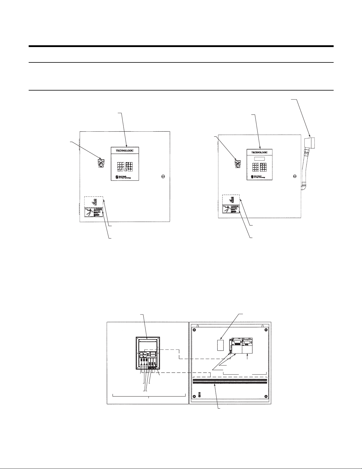
53
Appendix J – Drawings
Drawing # Description
1 Technologic 5500 Variable Primary Pump Controller – Door
2 Technologic 5500 Variable Primary Pump Controller – Subpanel
3 Operator Interface and CPU
OPERATOR INTERFACE
LOCAL-REMOTE-OFF
SWITCH
NAMEPLATE
MOUNTED INSIDE DOOR
WARNING LABEL
PART # S11550
NAMEPLATE
MOUNTED INSIDE DOOR
WARNING LABEL
PART # S11550
OPERATOR INTERFACE
LOCAL-REMOTE-OFF
SWITCH
PIN CONNECTOR
WITHOUT BYPASS
WITH BYPASS
Technologic 5500 Variable Primary Pump Controller – Door
(Front View Door Closed)
DRAWING 1.0
CPU & OPERATOR
INTERFACE
24 VDC POWER
SUPPLY
SLOT 1, RS COM PORT
SLOT 2, OPTIONAL I/O
SLOT 3, OPTIONAL I/O
RACK 1
SLOT 6, ANALOG
OUTPUT
SLOT 5, ANALOG INPUT
SLOT 4, DIGITAL INPUT
SLOT 2, DIGITAL OUTPUT
SLOT 1, DIGITAL OUTPUT
SLOT 0, CAN CONNECTION
RACK 2
CUSTOMER CONNECTIONS
Technologic 5500 Variable Primary Pump Controller – Subpanel
(FRONT View Door Open, Bypass & Non Bypass)
DRAWING 2.0
Page 54
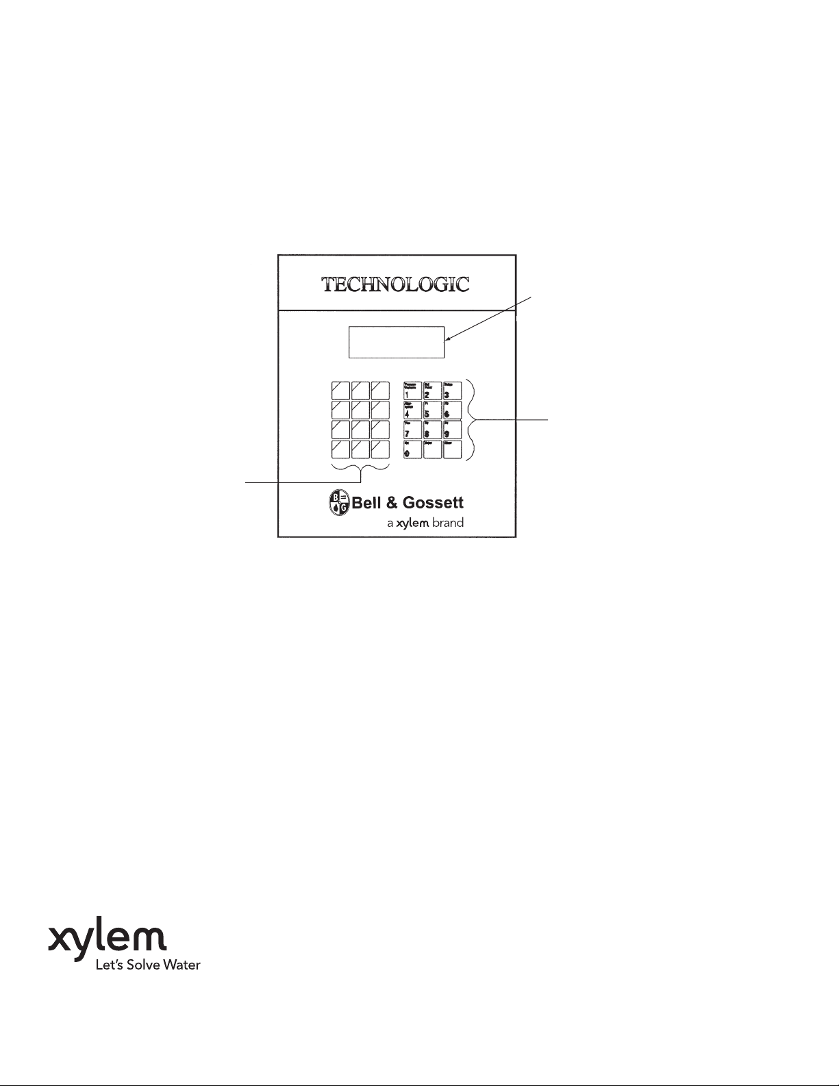
FUNCTION KEYS WITH LEDS
4 LINE DISPLAY
NUMERIC KEY PAD
Technologic 5500 Operator Interface and CPU
DRAWING 3.0
Xylem Inc.
10661 Newkirk Street
Dallas, TX 75220
Phone: (469) 221-1200
Fax: (214) 357-5861
www.xyleminc.com/brands/bellgossett
Bell & Gossett is a trademark of Xylem Inc. or one of its subsidiaries.
© 2012 Xylem Inc. S14334B August 2012
 Loading...