

INSTALLER: PLEASE LEAVE THIS MANUAL FOR THE OWNER’S USE.
Installation, Operation and Maintenance Instructions
SAFETY
INSTRUCTIONS
This safety alert symbol will be used in this manual and on the
ZoneSav Safety Instruction decal to draw attention to safety
related instructions. When used, the safety alert symbol means
ATTENTION! BECOME ALERT! YOUR SAFETY IS
INVOLVED! FAILURE TO FOLLOW THE INSTRUCTION
MAY RESULT IN A SAFETY HAZARD!
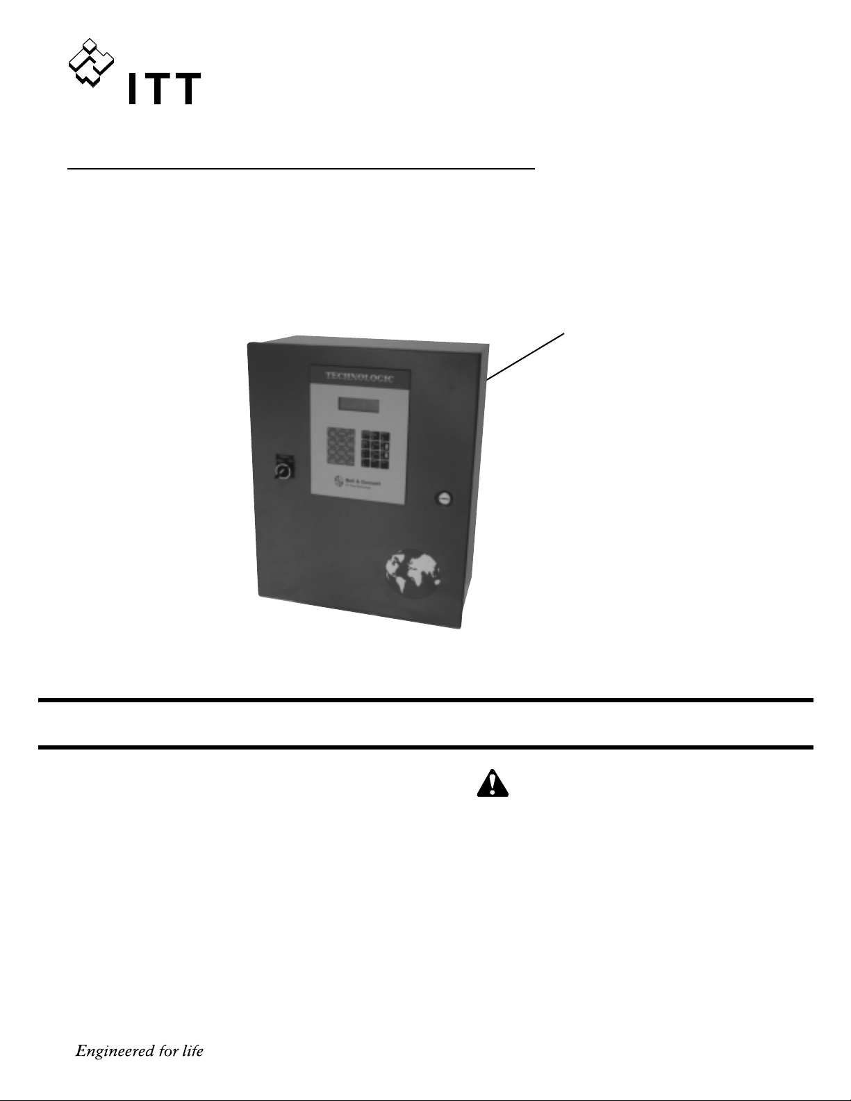
Technologic
™
5500 Series
ZoneSav Controller
WARNING LABEL PART #S11550
INSTALLED IN THIS LOCATION.
IF MISSING IT MUST BE REPLACED.
DESCRIPTION
Microprocessor based valve controller for HVAC systems.
The control panel consists of the following components:
microprocessor, operator interface with 4 line display and
membrane key pad, and 24 VDC power supply.
OPERATIONAL LIMITS
See the control panel nameplate for operating voltage, current
draw, as well as information on the equipment to be connected to the control panel.
VARIABLE SPEED PUMPING SYSTEMS
INSTRUCTION MANUAL
Bell & Gossett
Instruction Manual S14333

2
Preface
The following manual describes the microprocessor
based ZoneSav Controller. This unit is in the tradition
of the other members of the Technologic Control
Panels as it incorporates many original, novel, and
proprietary features that may only be found on B&G
controllers. Some of these features require special
emphasis here.
The controller is best described as a specific purpose
programmable valve controller. This means that the
hardware and software have been created for the control and diagnostics of valves with consideration for
their inherent characteristics. This results in an optimum valve controller without the cost of general purpose control hardware. Software is dedicated and
established for the unit only after extensive testing.
Changes to this software are not taken lightly and
must pass rigid version control.
The controller has the unique analog input protection
of other members of the control family. In the event of
a short circuit condition the current limit circuitry prevents failure of the analog input components.

3
SECTION 1 - GENERAL Page
1.1 Purpose of Manual . . . . . . . . . . . . . . . . . . . . . . . . . . . . . . . . . . . . . . . . . . . . . . . . . . . . . . . . . . . . .5
1.2 Safety . . . . . . . . . . . . . . . . . . . . . . . . . . . . . . . . . . . . . . . . . . . . . . . . . . . . . . . . . . . . . . . . . . . . .5
1.2.1 Safety Alert Symbol . . . . . . . . . . . . . . . . . . . . . . . . . . . . . . . . . . . . . . . . . . . . . . . . . . . . . . . . . .5
1.2.2 Safety Instruction Decal . . . . . . . . . . . . . . . . . . . . . . . . . . . . . . . . . . . . . . . . . . . . . . . . . . . . . . .5
1.2.3 Valve Safety . . . . . . . . . . . . . . . . . . . . . . . . . . . . . . . . . . . . . . . . . . . . . . . . . . . . . . . . . . . . . . . .5
1.2.4 Closed System Safety Measures . . . . . . . . . . . . . . . . . . . . . . . . . . . . . . . . . . . . . . . . . . . . . . . .5
1.3 Location . . . . . . . . . . . . . . . . . . . . . . . . . . . . . . . . . . . . . . . . . . . . . . . . . . . . . . . . . . . . . . . . . . . . .6
1.4 Storage . . . . . . . . . . . . . . . . . . . . . . . . . . . . . . . . . . . . . . . . . . . . . . . . . . . . . . . . . . . . . . . . . . . . .6
1.5 Handling . . . . . . . . . . . . . . . . . . . . . . . . . . . . . . . . . . . . . . . . . . . . . . . . . . . . . . . . . . . . . . . . . . . . .6
1.6 Temperature and Ventilation . . . . . . . . . . . . . . . . . . . . . . . . . . . . . . . . . . . . . . . . . . . . . . . . . . . . . .6
1.7 Input Voltage . . . . . . . . . . . . . . . . . . . . . . . . . . . . . . . . . . . . . . . . . . . . . . . . . . . . . . . . . . . . . . . . . .6
1.8 Ground Connections . . . . . . . . . . . . . . . . . . . . . . . . . . . . . . . . . . . . . . . . . . . . . . . . . . . . . . . . . . . .6
1.9 Power Wiring . . . . . . . . . . . . . . . . . . . . . . . . . . . . . . . . . . . . . . . . . . . . . . . . . . . . . . . . . . . . . . . . . .6
1.10 Analog Signal Wiring . . . . . . . . . . . . . . . . . . . . . . . . . . . . . . . . . . . . . . . . . . . . . . . . . . . . . . . . . . . .6
1.11 Field Connection Diagrams . . . . . . . . . . . . . . . . . . . . . . . . . . . . . . . . . . . . . . . . . . . . . . . . . . . . . . .6
1.11.1 Analog Inputs . . . . . . . . . . . . . . . . . . . . . . . . . . . . . . . . . . . . . . . . . . . . . . . . . . . . . . . . . . . . . . .6
1.11.2 Analog Inputs with External Power . . . . . . . . . . . . . . . . . . . . . . . . . . . . . . . . . . . . . . . . . . . . . .6
1.11.3 User Configurable I/O . . . . . . . . . . . . . . . . . . . . . . . . . . . . . . . . . . . . . . . . . . . . . . . . . . . . . . . . .7
1.11.4 Valve . . . . . . . . . . . . . . . . . . . . . . . . . . . . . . . . . . . . . . . . . . . . . . . . . . . . . . . . . . . . . . . . . . . . .7
1.11.5 Local-Off-Remote Switch . . . . . . . . . . . . . . . . . . . . . . . . . . . . . . . . . . . . . . . . . . . . . . . . . . . . . .7
SECTION 2 - OPERATION INTERFACE
2.1 Power-up . . . . . . . . . . . . . . . . . . . . . . . . . . . . . . . . . . . . . . . . . . . . . . . . . . . . . . . . . . . . . . . . . . . . .7
2.2 ZoneSav Controller Screen . . . . . . . . . . . . . . . . . . . . . . . . . . . . . . . . . . . . . . . . . . . . . . . . . . . . . . .7
2.3 Key Functionality . . . . . . . . . . . . . . . . . . . . . . . . . . . . . . . . . . . . . . . . . . . . . . . . . . . . . . . . . . . . . . .7
2.4 LEDs . . . . . . . . . . . . . . . . . . . . . . . . . . . . . . . . . . . . . . . . . . . . . . . . . . . . . . . . . . . . . . . . . . . . .7
SECTION 3 - SETUP SELECTION
3.1 Sensor Setup . . . . . . . . . . . . . . . . . . . . . . . . . . . . . . . . . . . . . . . . . . . . . . . . . . . . . . . . . . . . . . . . . .8
3.1.1 Sensor Settings . . . . . . . . . . . . . . . . . . . . . . . . . . . . . . . . . . . . . . . . . . . . . . . . . . . . . . . . . . . . .8
3.1.1.1 Sensor Number . . . . . . . . . . . . . . . . . . . . . . . . . . . . . . . . . . . . . . . . . . . . . . . . . . . . . . . . . . .8
3.1.1.2 Sensor Edit . . . . . . . . . . . . . . . . . . . . . . . . . . . . . . . . . . . . . . . . . . . . . . . . . . . . . . . . . . . . . .8
3.1.1.3 Sensor Type . . . . . . . . . . . . . . . . . . . . . . . . . . . . . . . . . . . . . . . . . . . . . . . . . . . . . . . . . . . . . .9
3.1.1.4 Sensor Span . . . . . . . . . . . . . . . . . . . . . . . . . . . . . . . . . . . . . . . . . . . . . . . . . . . . . . . . . . . . .9
3.1.1.5 Sensor Zero . . . . . . . . . . . . . . . . . . . . . . . . . . . . . . . . . . . . . . . . . . . . . . . . . . . . . . . . . . . . . .9
3.1.1.6 Sensor Override . . . . . . . . . . . . . . . . . . . . . . . . . . . . . . . . . . . . . . . . . . . . . . . . . . . . . . . . . . .9
3.1.1.7 Do Another . . . . . . . . . . . . . . . . . . . . . . . . . . . . . . . . . . . . . . . . . . . . . . . . . . . . . . . . . . . . . . .9
3.1.2 Sensor Log Rate . . . . . . . . . . . . . . . . . . . . . . . . . . . . . . . . . . . . . . . . . . . . . . . . . . . . . . . . . . . . .9
3.2 Valve Setup . . . . . . . . . . . . . . . . . . . . . . . . . . . . . . . . . . . . . . . . . . . . . . . . . . . . . . . . . . . . . . . . . . .9
3.2.1 Valve Position Limit . . . . . . . . . . . . . . . . . . . . . . . . . . . . . . . . . . . . . . . . . . . . . . . . . . . . . . . . .10
3.2.2 Valve Log Rate . . . . . . . . . . . . . . . . . . . . . . . . . . . . . . . . . . . . . . . . . . . . . . . . . . . . . . . . . . . . .10
3.2.3 Valve Signal . . . . . . . . . . . . . . . . . . . . . . . . . . . . . . . . . . . . . . . . . . . . . . . . . . . . . . . . . . . . . . .10
3.3 System Setup . . . . . . . . . . . . . . . . . . . . . . . . . . . . . . . . . . . . . . . . . . . . . . . . . . . . . . . . . . . . . . . .10
3.3.1 System Temperature Limit . . . . . . . . . . . . . . . . . . . . . . . . . . . . . . . . . . . . . . . . . . . . . . . . . . . .11
3.3.2 PID Setup . . . . . . . . . . . . . . . . . . . . . . . . . . . . . . . . . . . . . . . . . . . . . . . . . . . . . . . . . . . . . . . . .11
3.3.2.1 PID Gains . . . . . . . . . . . . . . . . . . . . . . . . . . . . . . . . . . . . . . . . . . . . . . . . . . . . . . . . . . . . . . .11
3.3.2.2 Setpoint Indexing . . . . . . . . . . . . . . . . . . . . . . . . . . . . . . . . . . . . . . . . . . . . . . . . . . . . . . . . .11
3.3.2.3 Heat/Cool . . . . . . . . . . . . . . . . . . . . . . . . . . . . . . . . . . . . . . . . . . . . . . . . . . . . . . . . . . . . . . .12
3.3.2.4 Auto Tune . . . . . . . . . . . . . . . . . . . . . . . . . . . . . . . . . . . . . . . . . . . . . . . . . . . . . . . . . . . . . .12
3.3.2.5 Optimize . . . . . . . . . . . . . . . . . . . . . . . . . . . . . . . . . . . . . . . . . . . . . . . . . . . . . . . . . . . . . . . .13
3.3.3 Alarms Setup . . . . . . . . . . . . . . . . . . . . . . . . . . . . . . . . . . . . . . . . . . . . . . . . . . . . . . . . . . . . . .13
3.3.4 Flow Limit . . . . . . . . . . . . . . . . . . . . . . . . . . . . . . . . . . . . . . . . . . . . . . . . . . . . . . . . . . . . . . . . .13
3.3.5 System Purge . . . . . . . . . . . . . . . . . . . . . . . . . . . . . . . . . . . . . . . . . . . . . . . . . . . . . . . . . . . . . .13
3.3.6 Reset Totals . . . . . . . . . . . . . . . . . . . . . . . . . . . . . . . . . . . . . . . . . . . . . . . . . . . . . . . . . . . . . . .14
3.3.7 Date/Time Setup . . . . . . . . . . . . . . . . . . . . . . . . . . . . . . . . . . . . . . . . . . . . . . . . . . . . . . . . . . . .14
3.3.8 Password Setup . . . . . . . . . . . . . . . . . . . . . . . . . . . . . . . . . . . . . . . . . . . . . . . . . . . . . . . . . . . .14
3.3.9 I/O Setup . . . . . . . . . . . . . . . . . . . . . . . . . . . . . . . . . . . . . . . . . . . . . . . . . . . . . . . . . . . . . . . . .15
3.3.9.1 DI . . . . . . . . . . . . . . . . . . . . . . . . . . . . . . . . . . . . . . . . . . . . . . . . . . . . . . . . . . . . . . . . . . . .15
3.3.9.2 DO . . . . . . . . . . . . . . . . . . . . . . . . . . . . . . . . . . . . . . . . . . . . . . . . . . . . . . . . . . . . . . . . . . . .15
3.3.9.3 AO . . . . . . . . . . . . . . . . . . . . . . . . . . . . . . . . . . . . . . . . . . . . . . . . . . . . . . . . . . . . . . . . . . . .16
3.3.10 Communication Setup . . . . . . . . . . . . . . . . . . . . . . . . . . . . . . . . . . . . . . . . . . . . . . . . . . . . . . .16
3.3.10.1 BACnet . . . . . . . . . . . . . . . . . . . . . . . . . . . . . . . . . . . . . . . . . . . . . . . . . . . . . . . . . . . . . . . .16
3.3.10.2 Metasys N2 . . . . . . . . . . . . . . . . . . . . . . . . . . . . . . . . . . . . . . . . . . . . . . . . . . . . . . . . . . . . .17
3.3.10.3 Modbus . . . . . . . . . . . . . . . . . . . . . . . . . . . . . . . . . . . . . . . . . . . . . . . . . . . . . . . . . . . . . . . .17
3.3.10.4 BACnet/IP . . . . . . . . . . . . . . . . . . . . . . . . . . . . . . . . . . . . . . . . . . . . . . . . . . . . . . . . . . . . . .17
3.3.11 Special Functions . . . . . . . . . . . . . . . . . . . . . . . . . . . . . . . . . . . . . . . . . . . . . . . . . . . . . . . . . . .18
3.3.11.1 Summer/Winter . . . . . . . . . . . . . . . . . . . . . . . . . . . . . . . . . . . . . . . . . . . . . . . . . . . . . . . . . .18
3.3.12 Save to Flash . . . . . . . . . . . . . . . . . . . . . . . . . . . . . . . . . . . . . . . . . . . . . . . . . . . . . . . . . . . . . .18
3.3.13 Load to Flash . . . . . . . . . . . . . . . . . . . . . . . . . . . . . . . . . . . . . . . . . . . . . . . . . . . . . . . . . . . . . .18
3.3.14 Contrast . . . . . . . . . . . . . . . . . . . . . . . . . . . . . . . . . . . . . . . . . . . . . . . . . . . . . . . . . . . . . . . . . .18
Index

4
INDEX (continued)
3.4 Test Selection . . . . . . . . . . . . . . . . . . . . . . . . . . . . . . . . . . . . . . . . . . . . . . . . . . . . . . . . . . . . . . . .18
3.4.1 DI Test . . . . . . . . . . . . . . . . . . . . . . . . . . . . . . . . . . . . . . . . . . . . . . . . . . . . . . . . . . . . . . . . . . .19
3.4.2 DO Test . . . . . . . . . . . . . . . . . . . . . . . . . . . . . . . . . . . . . . . . . . . . . . . . . . . . . . . . . . . . . . . . . .19
3.4.3 AI Test . . . . . . . . . . . . . . . . . . . . . . . . . . . . . . . . . . . . . . . . . . . . . . . . . . . . . . . . . . . . . . . . . . .19
3.4.4 AO Test . . . . . . . . . . . . . . . . . . . . . . . . . . . . . . . . . . . . . . . . . . . . . . . . . . . . . . . . . . . . . . . . . . .19
3.4.5 LED Test . . . . . . . . . . . . . . . . . . . . . . . . . . . . . . . . . . . . . . . . . . . . . . . . . . . . . . . . . . . . . . . . . .19
3.4.6 Key Test . . . . . . . . . . . . . . . . . . . . . . . . . . . . . . . . . . . . . . . . . . . . . . . . . . . . . . . . . . . . . . . . . .19
3.4.7 Display Test . . . . . . . . . . . . . . . . . . . . . . . . . . . . . . . . . . . . . . . . . . . . . . . . . . . . . . . . . . . . . . .19
3.4.8 Comm Test . . . . . . . . . . . . . . . . . . . . . . . . . . . . . . . . . . . . . . . . . . . . . . . . . . . . . . . . . . . . . . . .19
3.5 Default Setup . . . . . . . . . . . . . . . . . . . . . . . . . . . . . . . . . . . . . . . . . . . . . . . . . . . . . . . . . . . . . . . . .20
SECTION 4 - OPERATION . . . . . . . . . . . . . . . . . . . . . . . . . . . . . . . . . . . . . . . . . . . . . . . . . . . . . . . . . . . . .20
4.1 Status Screens . . . . . . . . . . . . . . . . . . . . . . . . . . . . . . . . . . . . . . . . . . . . . . . . . . . . . . . . . . . . . . .20
4.1.1 ZoneSav Controller Screen . . . . . . . . . . . . . . . . . . . . . . . . . . . . . . . . . . . . . . . . . . . . . . . . . . .21
4.1.2 Temperature Status . . . . . . . . . . . . . . . . . . . . . . . . . . . . . . . . . . . . . . . . . . . . . . . . . . . . . . . . .21
4.1.3 Flow Status . . . . . . . . . . . . . . . . . . . . . . . . . . . . . . . . . . . . . . . . . . . . . . . . . . . . . . . . . . . . . . . .21
4.1.4 Valve Status . . . . . . . . . . . . . . . . . . . . . . . . . . . . . . . . . . . . . . . . . . . . . . . . . . . . . . . . . . . . . . .21
4.2 Valve Operation . . . . . . . . . . . . . . . . . . . . . . . . . . . . . . . . . . . . . . . . . . . . . . . . . . . . . . . . . . . . . . .21
4.2.1 Manual Valve Operation . . . . . . . . . . . . . . . . . . . . . . . . . . . . . . . . . . . . . . . . . . . . . . . . . . . . . .21
4.2.2 Auto Valve Operation . . . . . . . . . . . . . . . . . . . . . . . . . . . . . . . . . . . . . . . . . . . . . . . . . . . . . . . .21
4.3 Setpoint Modification . . . . . . . . . . . . . . . . . . . . . . . . . . . . . . . . . . . . . . . . . . . . . . . . . . . . . . . . . .21
4.4 Process Variable Monitoring . . . . . . . . . . . . . . . . . . . . . . . . . . . . . . . . . . . . . . . . . . . . . . . . . . . . .22
4.5 Alarms . . . . . . . . . . . . . . . . . . . . . . . . . . . . . . . . . . . . . . . . . . . . . . . . . . . . . . . . . . . . . . . . . . . .22
4.6 Warnings . . . . . . . . . . . . . . . . . . . . . . . . . . . . . . . . . . . . . . . . . . . . . . . . . . . . . . . . . . . . . . . . . . . .22
4.7 Log Selection . . . . . . . . . . . . . . . . . . . . . . . . . . . . . . . . . . . . . . . . . . . . . . . . . . . . . . . . . . . . . . . .22
4.7.1 Averages . . . . . . . . . . . . . . . . . . . . . . . . . . . . . . . . . . . . . . . . . . . . . . . . . . . . . . . . . . . . . . . . . .23
4.7.2 Totals . . . . . . . . . . . . . . . . . . . . . . . . . . . . . . . . . . . . . . . . . . . . . . . . . . . . . . . . . . . . . . . . . . . .23
4.7.3 Alarm Log . . . . . . . . . . . . . . . . . . . . . . . . . . . . . . . . . . . . . . . . . . . . . . . . . . . . . . . . . . . . . . . . .23
4.7.4 Valve Log . . . . . . . . . . . . . . . . . . . . . . . . . . . . . . . . . . . . . . . . . . . . . . . . . . . . . . . . . . . . . . . . .23
4.7.5 Data Log . . . . . . . . . . . . . . . . . . . . . . . . . . . . . . . . . . . . . . . . . . . . . . . . . . . . . . . . . . . . . . . . . .23
4.7.6 Operation Log . . . . . . . . . . . . . . . . . . . . . . . . . . . . . . . . . . . . . . . . . . . . . . . . . . . . . . . . . . . . . .24
4.7.7 Power Logl . . . . . . . . . . . . . . . . . . . . . . . . . . . . . . . . . . . . . . . . . . . . . . . . . . . . . . . . . . . . . . . .24
4.7.8 Service Log . . . . . . . . . . . . . . . . . . . . . . . . . . . . . . . . . . . . . . . . . . . . . . . . . . . . . . . . . . . . . . . .24
4.7.8.1 System Log . . . . . . . . . . . . . . . . . . . . . . . . . . . . . . . . . . . . . . . . . . . . . . . . . . . . . . . . . . . . .24
4.7.8.2 Operating Hours Log . . . . . . . . . . . . . . . . . . . . . . . . . . . . . . . . . . . . . . . . . . . . . . . . . . . . . .24
4.7.9 Auto-Tune Log . . . . . . . . . . . . . . . . . . . . . . . . . . . . . . . . . . . . . . . . . . . . . . . . . . . . . . . . . . . . .24
SECTION 5 - MAINTENANCE . . . . . . . . . . . . . . . . . . . . . . . . . . . . . . . . . . . . . . . . . . . . . . . . . . . . . . . . . .25
5.1 Technical Overview . . . . . . . . . . . . . . . . . . . . . . . . . . . . . . . . . . . . . . . . . . . . . . . . . . . . . . . . . . . .25
5.2 Digital Inputs . . . . . . . . . . . . . . . . . . . . . . . . . . . . . . . . . . . . . . . . . . . . . . . . . . . . . . . . . . . . . . . . .25
5.3 Digital Outputs . . . . . . . . . . . . . . . . . . . . . . . . . . . . . . . . . . . . . . . . . . . . . . . . . . . . . . . . . . . . . . .25
5.4 Analog Inputs . . . . . . . . . . . . . . . . . . . . . . . . . . . . . . . . . . . . . . . . . . . . . . . . . . . . . . . . . . . . . . . .25
5.5 Memory . . . . . . . . . . . . . . . . . . . . . . . . . . . . . . . . . . . . . . . . . . . . . . . . . . . . . . . . . . . . . . . . . . . .25
5.6 CPU . . . . . . . . . . . . . . . . . . . . . . . . . . . . . . . . . . . . . . . . . . . . . . . . . . . . . . . . . . . . . . . . . . . .25
5.7 Power Supply . . . . . . . . . . . . . . . . . . . . . . . . . . . . . . . . . . . . . . . . . . . . . . . . . . . . . . . . . . . . . . . .25
5.8 Protection . . . . . . . . . . . . . . . . . . . . . . . . . . . . . . . . . . . . . . . . . . . . . . . . . . . . . . . . . . . . . . . . . . .25
5.9 Instruments and their Use . . . . . . . . . . . . . . . . . . . . . . . . . . . . . . . . . . . . . . . . . . . . . . . . . . . . . . .25
5.9.1 AC/DC Voltmeter . . . . . . . . . . . . . . . . . . . . . . . . . . . . . . . . . . . . . . . . . . . . . . . . . . . . . . . . . . .25
5.9.2 Ohmmeter . . . . . . . . . . . . . . . . . . . . . . . . . . . . . . . . . . . . . . . . . . . . . . . . . . . . . . . . . . . . . . . . .25
5.9.3 Milliamp Meter . . . . . . . . . . . . . . . . . . . . . . . . . . . . . . . . . . . . . . . . . . . . . . . . . . . . . . . . . . . . .25
5.9.4 Signal Generator (analyzer) – recommended . . . . . . . . . . . . . . . . . . . . . . . . . . . . . . . . . . . . . .25
5.10 Field Repair . . . . . . . . . . . . . . . . . . . . . . . . . . . . . . . . . . . . . . . . . . . . . . . . . . . . . . . . . . . . . . . . . .26
5.11 Special Programs . . . . . . . . . . . . . . . . . . . . . . . . . . . . . . . . . . . . . . . . . . . . . . . . . . . . . . . . . . . . .26
5.12 Program Updating . . . . . . . . . . . . . . . . . . . . . . . . . . . . . . . . . . . . . . . . . . . . . . . . . . . . . . . . . . . . .26
5.13 Controller Information Screen . . . . . . . . . . . . . . . . . . . . . . . . . . . . . . . . . . . . . . . . . . . . . . . . . . . .26
5.14 Maintenance (Physical) . . . . . . . . . . . . . . . . . . . . . . . . . . . . . . . . . . . . . . . . . . . . . . . . . . . . . . . . .26
5.14.1 Electrical . . . . . . . . . . . . . . . . . . . . . . . . . . . . . . . . . . . . . . . . . . . . . . . . . . . . . . . . . . . . . . . . . .26
5.14.2 Mechanical . . . . . . . . . . . . . . . . . . . . . . . . . . . . . . . . . . . . . . . . . . . . . . . . . . . . . . . . . . . . . . . .26
APPENDIX A System Piping and Unit Installation – Final Check List . . . . . . . . . . . . . . . . . . . . . . . . . . .27
APPENDIX B Electrical Wiring and Control Settings – Final Check List . . . . . . . . . . . . . . . . . . . . . . . . . .27
APPENDIX C Valid I/O Codes . . . . . . . . . . . . . . . . . . . . . . . . . . . . . . . . . . . . . . . . . . . . . . . . . . . . . . . . . .28
APPENDIX D BACnet Protocol Implementation Conformance Statement for BACnet IP . . . . . . . . . . . .29
APPENDIX E BACnet Protocol Implementation Conformance Statement for BACnet MS/TP . . . . . . . . .30
APPENDIX F BACnet Communications Points . . . . . . . . . . . . . . . . . . . . . . . . . . . . . . . . . . . . . . . . . . . . .31
APPENDIX G LonWorks Communication Points . . . . . . . . . . . . . . . . . . . . . . . . . . . . . . . . . . . . . . . . . . . .32
APPENDIX H Metasys N2 Communications Points . . . . . . . . . . . . . . . . . . . . . . . . . . . . . . . . . . . . . . . . .33
APPENDIX I Modbus Communications Points . . . . . . . . . . . . . . . . . . . . . . . . . . . . . . . . . . . . . . . . . . . .34
APPENDIX J Drawings . . . . . . . . . . . . . . . . . . . . . . . . . . . . . . . . . . . . . . . . . . . . . . . . . . . . . . . . . . . .35-37
NOTE: The information contained in this manual is intended to assist operating personnel by providing information on the char-
acteristics of the purchased equipment.
It does not relieve the user of the responsibility to adhere to local codes and ordinances and the use of accepted practices in
the installation, operation and maintenance of this equipment.
Further information pertaining to the installation, operation, and maintenance of your ZoneSave Controller can be found in the
I.O.M.s for the associated equipment provided see Section 5, Maintenance, for a list of relevant manuals.
1.1
Purpose of Manual
This manual is furnished to acquaint you with some
of the practical ways to install, operate, and maintain
this unit. Read it carefully before doing any work on
your unit and keep it handy for future reference.
Equipment cannot operate well without proper care.
To keep this unit at top efficiency, follow the recommended installation and servicing procedures outlined in this manual.
1.2 Safety
1.2.1 Safety Alert Symbol
SAFETY INSTRUCTION
This safely alert symbol will be used in this manual
and on the unit safety instruction to draw attention to
safety related instructions. When used the safety alert
symbol means
ATTENTION BECOME ALERT!
YOUR SAFETY IS INVOLVED! FAILURE TO FOLLOW THIS INSTRUCTION MAY RESULT IN A
SAFETY HAZARD.
1.2.2 Safety Instruction Decal
Your ZoneSav Controller should have a safety
instruction decal (part # S11550). If the decal is
missing or illegible contact your local B&G representative for a replacement.
1.2.3 Valve Safety
Ground fault protection should be sized properly.
Refer to local electrical codes for sizing and
selection.
Refer to the valve manufacturer's I.O.M. for specific
installation information.
Even when the valve is stopped, it should be considered alive as long as its controller is energized. Keep
hands away from the valve until the power is disconnected from the valve controller.
1.2.4
Closed System Safety Measures
Important:
Do not install and operate the ITT Bell &
Gossett ZoneSav Controller in a closed system
unless the system is constructed with properly sized
safety and control devices. Such devices include the
use of properly sized and located pressure relief
valves, compression tanks, pressure controls, temperature controls and flow controls as appropriate. If
the system does not include these devices, consult
the responsible engineer or architect before making
pumps operational.
1.3
Location
Install the ZoneSav Controller appropriately for ease of
inspection, maintenance and service. Observe local
electrical codes concerning control panel spacing.
5
Section 1 - General
Glossary of Terms
I.O.M. – Installation Operation Manual
LED – Light emitting diode, located on OIP and controller
OIP – Operator Interface Panel
PID – Proportional Integral Derivative; 3 variables required
for error control
Process Variable – Signal generated by a sensor that is set
up to control the system
Proof timer – Minimum time period before controller acknowledges an input; time period for which a signal must be stable
before it is accepted by the controller as a sustained and
valid signal
RTC – Real time clock
RTD – Resistive temperature device used to supply tempera-
ture signals to the PLC
BAS – Building Automation System
DANGER: The heating of water and other fluids causes
volumetric expansion. The associated forces may
cause failure of system components and releases of high
temperature fluids. This will be prevented by installing properly sized and located pressure relief valves and compression
tanks.
FAILURE TO FOLLOW THESE INSTRUCTIONS
CAN RESULT IN SERIOUS PROPERTY DAMAGE AND
SERIOUS PERSONAL INJURY OR DEATH.
DANGER: Heavy load, may drop if not lifted properly.
Do not lift the entire unit by the motor eyebolts. Lift the
unit with slings placed under the unit base rails.
FAILURE
TO FOLLOW THESE INSTRUCTIONS COULD RESULT
IN SERIOUS PERSONAL INJURY, DEATH, AND/OR
PROPERTY DAMAGE.
6
1.4
Storage
For long periods of storage, the unit should be
covered to prevent corrosion and contamination from
dirt. It should be STORED in a clean, dry location
between -20 and +60ºC. The relative humidity should
not exceed 85%. The unit should be checked periodically to ensure that no condensation has formed.
After storage, check that it is dry before applying
power.
1.5
Handling
Care should be taken to prevent damage due to
dropping or jolting when moving the ZoneSav
Controller. Transportation damage should be brought
to the carrier's attention immediately upon receipt.
1.6 Temperature and Ventilation
All electrical equipment is susceptible to failure if
operated in ambient temperatures outside of its rating. The OPERATING temperature range for this unit
is 0 to 40°C. The relative humidity should not exceed
95% non-condensing. The unit should not be operated outside these extremes.
1.7
Input Voltage
The ZoneSav Controller can be set up to operate
across a broad range of voltages. It was factory set
to operate on the voltage shown on the nameplate.
The voltage tolerance is +10/-5% and phase to
phase voltage must not have an imbalance greater
than 5 VAC.
1.8
Ground Connections
A grounding terminal is provided for a dedicated
ground wire connection. All provisions of the
National Electrical Code and local codes must be
followed.
1.9
Power Wiring
Power wire types and sizes must be selected based
upon conformance with the National Electrical Code
and all local codes and restrictions. In addition, only
copper (Cu) wire rated for 75°C (minimum) may be
used for the power connections. Refer to the input
current as listed on the nameplate on the enclosure
door when sizing wire.
1.10
Analog Signal Wiring
Shielded cable (#22 AWG, Belden type 8762, Alpha
#2411, or equal) should be installed for all D.C. control wiring. The shield must be terminated in the
Technologic Valve Controller panel.
Do not connect
the shield at the other end of the cable! Insulate
the shield so that no electrical connection is made
at the other end of the cable.
A twisted pair of #22
AWG conductors (Belden 8442 or equal) can be used
in place of shielded cable. The cable length must be
limited to 5,000 feet for #22 AWG wire.
1.11 Field Connection Diagrams
Refer to the valve I.O.M. for specific details unique
to the valve. Refer to the flow sensor/transmitter
I.O.M. for specific details unique to the flow sensor/
transmitter.
The Wiring Diagram(s), Dimensional Drawings and
Field Connection Diagram should be reviewed prior
to unit installation and operation.
The following sections are based on the installation of
standard ZoneSav product. Because customized
software and hardware is available, the installing contractor should base all wiring connections on the
wiring diagrams that accompany each controller.
These sections are meant to complement, not
replace, those wiring diagrams.
1.11.1
Analog Inputs
The ZoneSav Controller may be provided with the
capability to accept many analog inputs. Typically,
all analog inputs must be 4-20mA and powered by
the 24VDC power supply in the ZoneSav Controller.
1.11.2 Analog Inputs with External Power
The following steps describe the general procedure
for rewiring an analog input sensor when the sensor's
power source is not the ZoneSav Controller.
1) Turn off all power to the ZoneSav Controller.
2) Refer to the appropriate controller wiring diagram
that was shipped with unit. Locate the analog
input sensors on the wiring diagram that will be
rewired. They are labeled AI X.
3) Remove the 24 VDC positive (+) wire from TB 40
for the respective analog input sensor connection.
This wire needs to be removed completely or terminated if used as a jumper. This will prevent any
accidental contact with a negative (-) voltage
source (i.e. control panel) and avoid becoming a
short circuit. Care should be taken to ensure that
24 VDC positive (+) voltage is still provided to any
remaining sensors that will be powered by the
ZoneSav Controller.
4) Remove the 24 VDC negative (-) wire from TB 41
for the respective analog input sensor connection.
This wire needs to be removed completely or terminated if used as a jumper. This will prevent any
accidental contact with a positive (+) voltage
source and avoid becoming a short circuit. Care
should be taken to ensure that 24 VDC (-) negative
voltage is still provided to any remaining sensors
that will still be powered by the ZoneSav Controller.
WARNING: Prevent electrical shocks. Disconnect
the power supply before beginning installation.
FAILURE TO FOLLOW THESE INSTRUCTIONS COULD
RESULT IN SERIOUS PERSONAL INJURY, DEATH,
AND/OR PROPERTY DAMAGE.
WARNING: Conduit grounds are not adequate. A
separate ground wire must be attached to the ground
lug provided in the enclosure to avoid potential safety hazards.
FAILURE TO FOLLOW THESE INSTRUCTIONS
COULD RESULT IN SERIOUS PERSONAL INJURY,
DEATH, AND/OR PROPERTY DAMAGE.
WARNING: Prevent electrical shocks. Disconnect
the power supply before beginning installation.
FAILURE TO FOLLOW THESE INSTRUCTIONS COULD
RESULT IN SERIOUS PERSONAL INJURY, DEATH,
AND/OR PROPERTY DAMAGE.
7
5) Terminate the negative (-) wire of the sensor to TB
41 of the respective analog input sensor connection. Terminate the positive (+) wire of the sensor
to the terminal block which is connected to the
positive (+) terminal shown on the Analog input
card.
Note: Be certain that the power supplied to other terminal blocks has not been interrupted! The wires that
were removed in the preceding steps may have been
used as jumpers.
1.11.3 User Configurable I/O
The ZoneSav Controller comes equipped with the
capability to define the operation of any unused input
or output. Table 1 below shows the amount of each
type that is available for user setup on the standard
ZoneSav Controller. This does not include optional
I/O modules or the signals that are required for correct operation. Refer to Section 3.3.9 for detailed
information on the I/O Setup Menu.
I/O Type Amount Available
Digital Input (24V) 9
Digital Output (24V) 8 + 1 relay
Analog Output 1
Table 1: User Configuration I/O
1.11.4 Valve
The ZoneSav Controller sends a 4 - 20mA or 0 - 10V
signal to the valve. This signal can also be reversed.
See section 3.2.3, Valve Signal, for instructions on
how to change the signal sent to the valve. The Valve
must be configured to accept a 4 - 20mA or 0 - 10V
signal. All shields must be grounded, only in the
ZoneSav Controller, to prevent ground loops and
improper signals.
1.11.5
Local-Off-Remote Switch
In the LOCAL position, the panel is always energized.
With the LOCAL-OFF-REMOTE switch in REMOTE, a
contact closure from a remote source will energize
the panel. This signal can be supplied through any of
the communications protocols used or through a 24V
digital input.
Section 2 - Operator Interface
2.1 Power-Up
Put LOCAL-REMOTE-OFF (LRO) switch in the
LOCAL position.
Turn main disconnect on.
2.2
ZoneSav Controller Screen
Upon powering up the controller, the display will light
and show the ZoneSav Controller default screen
shown below. See section 4.1 for more description
of this screen and the neighboring status screens.
ZoneSav Controller
Version: #.#
MM/DD/YY HH:MM:SS A/P
Stop Man Heat Manual
2.3 Key Functionality
The names of the keys on the Operator Interface
Panel (OIP) are shown as CAPITAL LETTERS in this
manual. Table 2, on the next page, shows the functionality of the keys on the OIP.
2.4
LEDs
Table 3, shown on the next page, gives the meaning
of the LED states.
WARNING: Electrical shock hazard. Inspect all elec-
trical connections prior to powering the unit. Wiring
connections must be made by a qualified electrician in
accordance with all applicable codes, ordinances, and
good practices.
FAILURE TO FOLLOW THESE INSTRUCTIONS COULD RESULT IN SERIOUS PERSONAL
INJURY, DEATH, AND/OR PROPERTY DAMAGE.
WARNING: Electrical shock hazard. Multiple power
sources. The off position of the LOCAL-REMOTEOFF switch does not disconnect all of the power sources in
the technologic panel. All power sources must be disconnected prior to entering the control panel.
FAILURE TO
FOLLOW THESE INSTRUCTIONS COULD RESULT IN
SERIOUS PERSONAL INJURY, DEATH, AND/OR PROPERTY DAMAGE.

8
From the ZoneSav Controller screen, shown in section 2.2, press the SETUP key to get to the Setup
Selection screen shown below.
Setup Selection: 0
1 = Sensors 4 = Test
2 = Valve 5 = Default
3 = System 0 = Exit
Press the numeric key corresponding to the desired
Setup Selection submenu, and press ENTER.
3.1
Sensor Setup
From the Setup Selection Menu, shown in section 3,
press 1 and ENTER to get to the Sensor Setup
screen shown below.
Sensor Setup: #
1=Sensor Settings
2=Sensor Log Rate
0=Exit
Press the numeric key corresponding to the desired
Sensor Setup submenu and press ENTER.
3.1.1
Sensor Settings
3.1.1.1 Sensor Number
From the Sensor Setup screen, shown in section 3.1,
Press 1 and ENTER to get to the Sensor Number
screen shown below.
SENSOR NO: ##
Input the analog input number that will be modified,
and press ENTER.
3.1.1.2
Sensor Edit
After the analog input number is entered section
3.1.1.1, the Sensor Edit screen, shown below, will be
displayed.
Sensor# ## Type: (Type)
Span = 0 Zero = 0
Override:Y/N
Ok ? (Y/N)
Press YES and ENTER at the Ok prompt to accept
these values, and proceed to section 3.1.1.7. Press
NO and ENTER to modify these values, and go to
section 3.1.1.3.
Section 3 - Setup Selection
Key Name Functionality
START/STOP Starts and Stops System
AUTO/MANUAL Toggles operation mode
MANUAL VALVE Brings up the manual valve position screen. See section 4.2.1.
WARNING Brings up the active warnings if a warning exists (LED will blink when active)
PREV. SCREEN Navigates to neighboring screens (LED will blink when active)
NEXT SCREEN Navigates to neighboring screens (LED will blink when active)
HELP Brings up alarms. See section 4.5. If no alarm exists, help is available in every screen.
PROCESS VARIABLE/1 Brings up the Process Variable screen, shown in section 4.4, or used as a numeric key
SET POINT/2 Brings up the Set Point screen, shown in section 4.3, or used as a numeric key
SETUP/3 Brings up the Setup screen, shown in section 3, or used as a numeric key
F1/LOG/5 Brings up the Log Menu, shown in section 4.7, or used as a numeric key
F2/6 Used as a numeric key or an up arrow
YES/7 Used as a numeric key or YES
F3/INFO/8 Shows controller information screen, shown in section 5.13, or used as a numeric key
F4/9 Used as a numeric key or a down arrow
NO/0 Used as a numeric key or NO
ENTER Used to confirm entries and to advance to the next item if there are multiple fields
CLEAR Used to clear entries and to exit some screens
Table 2: Key Functionality
LED Description
START/STOP On = Start, Blinking = Stop
AUTO/MANUAL On = Auto, Blinking = Manual
MANUAL VALVE Blinks when system is on and in manual and in status screens to indicate it is active
WARNING Blinks when a warning exists and in status screens to indicate it is active
PREV. SCREEN Blinks when button is active
NEXT SCREEN Blinks when button is active
HELP Off = Brings up Help screen when pressed, Blinking = Brings up alarms when pressed.
Table 3

9
3.1.1.3
Sensor Type
If NO was selected in the Sensor Edit screen, shown
in section 3.1.1.2, the following will be displayed.
Sensor # ## Type: (Type)
1 = SysT 2 = ZST 3 = ZRT
4 = Flw 5 = Tmp 6 = VFbk
0 = None
Table 4, shown below, gives a description and the
units of each sensor type.
Selection Description Units
1=SysT System Temperature ˚F
2=ZST Zone Supply Temperature ˚F
3=ZRT Zone Return Temperature ˚F
4=Flw *Flow GPM
5=Temp Temperature (for display only) °F
6=VFbk Valve Feedback (for display only) %
0=None No Sensor N/A
Table 4: Sensor Types
Enter the numeric key corresponding to the type of
sensor you are setting up. The abbreviation for the
sensor type will appear in the upper right corner of
the display in the following screens. The ZoneSav
controller does not allow more than one sensor to
have types 1, 2, 3, 5, or 6.
*Note: A total of three flowmeters can be set up. The
smallest analog input number that has type "Flw" will
be the Zone Flow. It will be used for flow limit operation. See section 3.3.4 to set up a flow limit. The
other two flows will not be used in control algorithms.
They are for display only.
3.1.1.4
Sensor Span
After entering the sensor type in section 3.1.1.3, the
display will prompt the user for the sensor span as
shown below.
Sensor No ## Type: (Type)
Span = #####
Enter the span by pressing the appropriate numeric
keys and ENTER. Obtain the span of the sensor from
the nameplate on the sensor. The span is the numeric
value that corresponds to a 20mA signal.
3.1.1.5 Sensor Zero
After entering the sensor span in section 3.1.1.4, the
display will prompt the user for the zero of the sensor
as shown below.
Sensor No ## Type: (Type)
Span = ##### Zero = #####
Enter the desired zero value by pressing the appropriate numeric keys and ENTER. The Zero corresponds to the numeric value of the sensor at 4mA.
3.1.1.6
Sensor Override
After entering the sensor zero in section 3.1.1.5, the
display will prompt the user for Override (Yes/No) as
shown below.
Sensor No ## Type: (Type)
Span = # Zero = #
Override: Y/N
The controller is capable of accepting sensor input
either through a 4-20mA analog input or through the
communication port. See section 3.3.10 for available
protocols. The communication port must be set up
properly and connected to an external building
automation system (BAS).
Press YES and ENTER to receive the sensor signals
via the communication port. Press NO and ENTER to
receive the sensor signals via the analog input card.
After the selection is made, the controller will return
to the Sensor Edit screen shown in section 3.1.1.2.
3.1.1.7
Do Another
If YES was selected in the Sensor Edit screen, shown
in section 3.1.1.2, the display will show the following.
DO ANOTHER ? (Y/N)
Press YES and ENTER to set up another sensor, or
press NO and ENTER to return to the Sensor Setup
screen shown in section 3.1.
3.1.2
Sensor Log Rate
From the Sensor Setup screen, shown in section 3.1,
Press 2 and ENTER to get to the Sensor Log Rate
screen shown below.
Sensor Log Rate: #
0=None 2=Hr 4=Week
1=Min 3=Day 5=Month
OK ? (Y/N)
Press YES and ENTER to accept the current Sensor
Log Rate, or press NO and ENTER to edit the Sensor
Log Rate. See section 4.7.5 for more information on
the Data Log. See Table 5 for a description of the
Sensor Log Rate.
3.2
Valve Setup
From the Setup Selection screen, shown in section 3,
press 2 and ENTER to get to the Valve Setup screen
shown below.
SELECTION: # 0 = EXIT
1 = Valve Pos. Limit
2 = Valve Log Rate
3 = Valve Signal
Push the numeric key corresponding to the desired
Valve Setup submenu, and press ENTER to proceed.
Variable Description Default Value Range Field Value
Sensor Log Rate One data point is taken at the end of the interval 0 0-5
Table 5: Sensor Log Rate Variable

10
3.2.1
Valve Position Limit
From the Valve Setup screen, shown in section 3.2,
Press 1 and ENTER to get to the Valve Position Limit
screen shown below.
Valve Pos. Limit
Minimum: ###%
Maximum: ###%
0% = Closed OK ? (Y/N)
Press YES and ENTER to accept the values and
return to the Valve Setup screen, shown in section
3.2, or press NO and ENTER to edit the fields. See
Table 6 for a description of the Valve Position Limit
variables.
Note: The minimum and maximum valve position limits are ignored in manual operation mode.
3.2.2
Valve Log Rate
From the Valve Setup screen, shown in section 3.2,
Press 2 and ENTER to get to the Valve Log Rate
screen shown below.
Valve Log Rate: #
0=None 2=Hr 4=Week
1=Min 3=Day 5=Month
OK: ? (Y/N)
Press YES and ENTER to accept the current Valve
Log Rate, or press NO and ENTER to edit the Valve
Log Rate. See section 4.7.4 for more information on
the Valve Log. See Table 7 for a description of the
Valve Log Rate variables.
3.2.3
Valve Signal
From the Valve Setup screen, shown in section 3.2,
Press 3 and ENTER to get to the Valve Signal screen
shown below.
Valve Signal Type: #
1=4-20mA 2=0-10V
Signal Reversed: Y/N
OK: ? (Y/N)
Press YES and ENTER to accept the configuration
and return to the Valve Setup screen shown in section 3.2. Press NO and ENTER to edit the fields. See
Table 8 for a description of the Valve Signal variables.
3.3 System Setup
From the Setup Selection screen, shown in section 3,
press the 3 and ENTER to get to the System Setup
screens shown below.
Selection: # 0 = Exit
1 = System Temp Limit
2 = PID
3 = Alarms
Press NEXT SCREEN key or PREV. SCREEN to view
neighboring screens. There are five screens in this
menu. The remaining screens are shown below.
Selection: # 0 = Exit
4 = Flow Limit
5 = System Purge
6 = Reset Totals
Selection: # 0 = Exit
7 = Date, Time
8 = Password
9 = I/O Setup
Selection: # 0 = Exit
10 = Communication
11 = Special Function
12 = Save to Flash
Selection: # 0 = Exit
13 = Load From Flash
14 = Set Contrast
Press the numeric key corresponding to the desired
System Setup sub-menu, and press ENTER.
Variable Unit Description Default Value Range Field Value
Minimum % Minimum valve position in automatic operation mode 0 0-100
Maximum % Maximum valve position in automatic operation mode 100 0-100
Table 6: Valve Position Limit Variables
Variable Description Default Value Range Field Value
Valve Log Rate One data point is taken at the end of the interval 0 0-5
Table 7: Valve Log Rate Variables
Variable Description Default Value Range Field Value
Valve Signal Select 1 if the valve accepts a 4-20mA signal or select 1 1-2
Type 2 if it accepts a 0-10V signal
Signal Reversed Select N if the valve is closed at 4mA or 0V. Select Y if N Y/N
the valve is open at 4mA or 0V
Table 8: Valve Signal Variables

11
3.3.1
System Temperature Limit
From the System Setup Menu, shown in section 3.3,
press 1 and ENTER to get to the System Temperature Limit screen shown below.
System Temp Limit
Temp Limit = ###
Valve Opening = ###%
Timer = ###m OK ? (Y/N)
Press NO and ENTER to modify the fields, or press
YES and ENTER to exit back to accept the current
values and return to the System Setup screen, shown
in section 3.3. See Table 9 for a description of the
System Temperature Limit variables.
3.3.2
PID Setup
From the System Setup Menu, shown in section 3.3,
press 2 and ENTER to get to the PID Setup screen
shown below.
PID Selection: #
1 = Values 4 = AutoTune
2 = Index 5 = Optimize
3 = Heat/Cool 0 = Exit
Press the numeric key corresponding to the desired
PID Setup sub-menu, and press ENTER. Press 0 and
ENTER to return to the System Setup screen shown
in section 3.3.
3.3.2.1 PID Values
From the PID Setup screen, shown in section 3.3.2,
press 1 and ENTER to get to the PID Values screen
shown below.
(Type) PID VALUES
P = ###
I = ###
D = ### Ok ? (Y/N)
There is a different set of values for the zone supply
temperature, zone return temperature and flow.
Press NEXT SCREEN or PREV. SCREEN to change
the type of analog input.
The user should contact B&G if assistance is needed
in tuning the ZoneSav Controller's gains. Also see
section 3.3.2.4 for Auto-Tuning. To edit the fields,
press NO and ENTER. Press YES and ENTER to
accept the values. See Table 10 for a description of
the PID values variables.
3.3.2.2
Setpoint Indexing
From the PID Setup screen, shown in section 3.3.2,
press 2 and ENTER to get to the Setpoint Indexing
screen shown below.
Setpoint Indexing
Sup Idx = # ZSTmr = ## s
Ret Idx = # ZRTmr = ## s
Ok ? (Y/N)
Variable Unit Description Default Value Range Field Value
Temp °F If heating system, this is the low system temperature limit 55 0-999
Limit If cooling system, this is the high system temperature limit
Valve % Valve opens to this position when system temperature 50 0-100
Opening limit is exceeded
Timer minutes Valve will remain at the Valve Opening for the duration 1 0-99
of the timer
Table 9: System Temperature Limit Variables
Variable Description Default Default Default Field Field Field Range
Value Value Value Value Value Value
(ZS) (ZR) (FL) (ZS) (ZR) (FL)
Type ZS = zone supply N/A N/A N/A N/A N/A N/A N/A
ZR = zone return
FL = flow
PID-P Proportional value 400 400 20 1-999
PID-I Integral value 100 100 20 0-999
PID-D Derivative value 0 0 0 0-999
Table 10: PID Values

12
Setpoint Indexing is implemented when the system
supply temperature degrades to the point where it is
impossible to meet the setpoints in the system. In
this condition, the valve would normally go to the
wide open position to try to meet the setpoints.
However, if setpoint indexing is used, the ZoneSav
Controller can modify the setpoints in order to remain
in control. A warning is generated while the controller
is in this mode of operation.
To edit the fields, press NO and ENTER. Press YES
and ENTER to accept the values. See Table 11 for a
description of the Setpoint Indexing variables.
3.3.2.3
Heat/Cool
From the PID Setup Menu, shown in section 3.3.2,
press 3 and ENTER to get to the Heat/Cool screen
shown below.
Application Type: #
1:Heating
2:Cooling
Ok ? (Y/N)
Press YES and ENTER to accept the values and
return to the PID Setup Menu shown in section 3.3.2,
or press NO and ENTER to edit the field.
3.3.2.4
Auto Tune
From the PID Setup Menu, shown in section 3.3.2,
press 4 and ENTER to get to the Auto Tune screen
shown below.
Auto-Tune Select: #
ZS: (Message) 1=Start
ZR: (Message) 0=Stop
FL: (Message) Ok ? (Y/N)
Press YES and ENTER to return to the PID Setup
Menu shown in section 3.3.2. Press NO and ENTER
to edit the field. See Table 13 for a description of the
Auto Tune variables.
Auto-Tuning is used to find the optimal P, I, and D
values for the system being tuned. When the
process is started, the valve will be forced wide open.
It will remain there until the zone supply setpoint is
met. Then the valve will be forced closed. It will
remain there until the setpoint is no longer met. This
cycle will repeat 5 times. The message will change
from "Tune" to either "Comp" or "Err" indicating completion. Tuning of the zone return and flow values will
then commence. If an error occurs, auto tuning will
be aborted. The valve position and process variables
can be viewed in other screens during auto tuning.
The optimal P, I, and D will automatically be used.
These gains can be viewed or modified from the PID
Gains screen shown in section 3.3.2.1.
The controller must be stopped and in manual operation mode to begin the auto tuning process. Also,
make sure the zone return and zone supply setpoints
are set up and that they are realistic values. See section 4.3 for more information on modifying the setpoints. The setpoint used for flow will be 90% of the
flow limit value. Make sure that the flow limit value is
set up and realistic. See section 3.3.4 for more information on setting up a flow limit.
If a flowmeter is not used, the Auto-Tuning process
should be stopped manually. Wait for the message
for "FL" to be "Tune". Then enter a zero in the AutoTune Select field to stop the process. The gains for
zone supply and zone return will still be optimized
and used.
Variable Unit Description Default Value Range Field Value
Sup Idx °F Zone supply index: the difference between the system 0 0-20
supply temperature and the zone supply setpoint that will
be maintained. 0 will disable this mode of operation.
ZSTmr min Zone supply index timer: controlle will remain in zone 0 0-99
supply index mode for the duration of this timer
Ret Idx °F Zone return index: the difference between the system 0 0-20
supply temperature and the zone return setpoint that will
be maintained. 0 will disable this mode of operation.
ZRTmr min Zone return timer: controller will remain in zone supply 0 0-99
index mode for the duration of this timer
Table 11: Setpoint Indexing Variables
Variable Description Default Value Range Field Value
Application Select 1 if system is for heating, or select 2 if system 2 1-2
Type is for cooling
Table 12: Heat/Cool Variable
Variable Description Default Value Range
Auto-Tune Select 1 = Start Auto Tune Process 0 0-1
0 = End Auto Tune Process
Message Stop = Stopped, Tune = Tuning, Err = complete with error, N/A N/A
Comp = complete
Table 13: Auto Tune Variables

Table 14: Optimize Variables
13
If a "Tune" message does not change to "Comp" or
"Err" within 10 minutes, enter 0 to manually stop the
Auto-Tuning process. If the "Err" message is displayed in any of the fields, repeat the Auto-Tune
process. If the error persists, check the Auto-Tune
Log shown in section 4.7.9, record the information,
and contact B&G for assistance.
3.3.2.5
Optimize
From the PID Setup Menu, shown in section 3.3.2,
press 5 and ENTER to get to the Optimize screen
shown below.
PID Opti.: ? (Y/N)
Floating Range: ###%
Holding Time: ###s
Ok ? (Y/N)
Press YES and ENTER to accept the values and
return to the PID Setup Menu shown in section 3.3.2,
or press NO and ENTER to edit the fields. See Table
14 for a description of the Optimize Variables.
PID optimization is used to close the valve as much
as possible while still meeting the zone supply and
zone return setpoints.
3.3.3
Alarms Setup
From the System Setup Menu, shown in section 3.3,
press 3 and ENTER to get to the Alarms Setup
screen shown below.
AI Fail Pr. Tm = ##s
Ok ? (Y/N)
Press YES and ENTER to accept the value and return
to the System Setup Menu, shown in section 3.3, or
press NO and ENTER to edit the field. See Table 15
for a description of the Alarms Variables.
3.3.4 Flow Limit
From the System Setup screen, shown in section 3.3,
press 4 and ENTER to get to the Flow Limit screen
shown below.
Flow Limit
Pr. Tmr = ### sec
LimTm = #
AvgTmr = # Ok ? YN
To return to the System Setup Menu, shown in section 3.3, press YES and ENTER. To edit the fields,
press NO and ENTER. See Table 16 for a description of the Flow Limit variables. See Table 31 for
more information on flow limit operation.
3.3.5
System Purge
From the System Setup Menu, shown in section 3.3,
press 5 and ENTER to get to the System Purge
screen shown below.
Purge Timer = ###m
Valve Position = ###%
Ok ? (Y/N)
To return to the System Setup screen, shown in section 3.3, press YES and ENTER.
To edit the fields, press NO and ENTER. See Table
17 for a description of the Bypass Setup variables.
Variable Unit Description Default Value Range Field Value
PID Opti N/A Select Y to enable PID optimization or N to disable N Y/N
Floating % The percentage by which the valve position will be 3 0-20
Range decreased
Holding s Proof timer prior to decreasing valve position by the 20 0-999
Time floating range
Variable Unit Description Default Value Range Field Value
AI Fail Seconds Proof timer prior to setting an analog input failure alarm 10 0-999
Pr. Tm
Table 15: Alarm Variables
Variable Unit Description Default Value Range Field Value
Pr. Tmr Seconds Proof timer prior to starting flow limit operation 30 0-999
Lim Tmr Minutes The controller will remain in flow limit operation for the 0 0-999
duration of the timer, 0 will disable flow limit
Limit GPM Maximum flow before entering flow limit operation 40 0-65535
Table 16: Flow Limit Variables
Variable Description Default Value Range Field Value
Purge Timer The valve will remain at the Valve Position for the duration 0 0-30
of the Purge Timer. 0 min will disable purging.
Valve Position Valve will go to this position during purging. 100 0-100
Table 17: System Purge Variables

14
Purging is used to give the system time to react to
changing water temperatures on startup. If purging is
enabled, purging will occur every time the system is
started in automatic mode. Stopping and then starting the system while in automatic operation mode will
start the purging process. A command to purge the
system can also be initiated through a communications port. See Appendices F through I for the relevant communications point. When the system is
purging, "Purge" will be displayed in the Valve Status
screen shown in section 4.1.4.
3.3.6
Reset Totals
From the System Setup Menu, shown in section 3.3,
press 6 and ENTER to get to the Reset Totals screen
shown below.
Reset Total Values
Op Hours: Y/N
Gallons: Y/N
BTU: Y/N Ok ? (Y/N)
To return to the System Setup Menu, shown in section 3.3, press YES and ENTER. To edit the field,
press NO and ENTER. Table 18 gives a description
of the Reset Totals variables.
3.3.7 Date/Time Setup
From the System Setup Menu, shown in section 3.3,
press 7 and ENTER to get to the Date/Time Setup
screen shown below.
MM/DD/YYYY HH:MM:SS
Display 24 Hr Fmt: ? (Y/N)
Daylite Saving Tm: ? (Y/N)
Ok ? (Y/N)
To return to the System Setup Menu, shown in section 3.3, press YES/7 and ENTER. To edit the fields,
press NO and ENTER. See Table 19 for a description
of the Date/Time Setup variables.
3.3.8 Password Setup
From the System Setup Menu, shown in section 3.3,
press 8 and ENTER to get to the Password Setup
screen shown below.
Enable Password To:
Setup Menu ? (Y/N)
Set Point ? (Y/N)
Ok ? (Y/N)
To return to the System Setup Menu, shown in section 3.3, press YES and ENTER. To edit the fields,
press NO and ENTER. See Table 20 for a description
of the Password Setup variables.
Variable Description Default Value Range Field Value
Op Hours Set this to Y to reset the operating hours and N Y/N
commissioning date and time (see section 4.7.8.2)
GAL Set GAL to Y to reset the total gallons and Avg GPM N Y/N
(see sections 4.7.1 and 4.7.2)
BTU Set BTU to Y to reset the Avg TON, Avg MBH, and N Y/N
Tot KBTU (see sections 4.7.1 and 4.7.2)
Table 18: Reset Totals Variables
Variable Description Default Value Range Field Value
Setup Menu Enter YES for password protection of the entire setup N Y / N
menu
Set Point Enter YES for password protection of set point N Y / N
modification
Table 20: Password Variables
Variable Description Default Value Range Field Value
MM Current month (two digits), example: Jan. should be
created as 01
DD Current date (two digits), example: the 6th should be
entered as 06
YYYY Current year using all 4 digits
HH Hours (24 hour format), example: 9:00 p.m. should be
entered as 21
MM Minutes (two digits)
Display Enter YES to display the time in the 24 hour format. N Y/N
24 Hr Fmt Enter NO to display the time in AM/PM format.
Daylite Enter YES for automatic setback during daylight N Y/N
Saving TM saving time. Enter NO to disable the automatic setback
during daylight saving time.
Table 19: Date/Time Variables

15
If either of the above are set to YES the screen,
shown below, prompts the user to define the password.
ENTER NEW PASSWORD
>_______________<
Enter a password from 0-999999. Record it here or
somewhere else!
After entering a password the Verify Password screen
requires the user to confirm the password. If the confirmed number does not agree with the first number,
the Enter New Password screen is repeated to allow
the user to get both input screens to agree.
VERIFY THE PASSWORD
>_______________<
3.3.9 I/O Setup
From the System Setup Menu, shown in section 3.3,
press 9 and ENTER to get to the I/O Setup screen
shown below.
I/O Setup Select: #
1 = DI
2 = DO
3 = AO 0 = EXIT
Note:
The total available number of I/O to be config-
ured is dependent on the system setup. Complete all
previous setup screens, specifically sensors, prior to
completing the following.
3.3.9.1
DI
From the I/O Setup Menu, shown in section 3.3.9, press
1 and ENTER to get to the DI screen shown below.
Opt. DI = # Avail: = #
Code = # Delay = ##s
(Functionality)
Exit: ? (Y/N)
To return to the I/O Setup Menu, shown in section
3.3.9, press YES and ENTER. To edit the fields,
press NO and ENTER. See Table 21 for a description
of the DI variables.
3.3.9.2
DO
From the I/O Setup Menu, shown in section 3.3.9, press
2 and ENTER to get to the DO screen shown below.
Available DOs = ##
Opt. DO# = #### Code = ###
(Functionality)
Exit: ? (Y/N)
To return to the I/O Setup Menu, shown in section
3.3.9, press YES and ENTER. To edit the fields,
press NO/0 and ENTER. See Table 22 for a description of the DO variables.
Note: DO#1-8 are 24V transistor outputs. DO#9 is a
relay.
Variable Unit Description Default Value Range Field Value
Opt. DI N/A Enter the DI # that will assume the desired functionality N/A 0-10
Avail N/A This variable is not modifiable. It is here to advise the N/A 0-9
user of how many digital inputs can be customized
Code N/A Defines the desired functionality of the input, valid codes 0 0-3
are defined in Appendix C of this manual
Delay Seconds Proof timer 0 0-999
Function- N/A This message will show the functionality of the code N/A N/A
ality that was entered
Table 21: DI Variables
Variable Description Default Value Range Field Value
Available DOs This screen can not be modified. It is here to advise the 9 0-9
user of how many digital outputs can be customized
Opt. DO# Enter the DO# that will assume the desired functionality N/A 0-9
Code Enter the code to defines the desired functionality of the 0 0-6
output. Valid codes are defined in Appendix C of this
manual
Functionality This message will show the functionality of the code N/A N/A
that was entered
Table 22: DO Variables

16
3.3.9.3
AO
From the I/O Setup Menu, shown in section 3.3.9,
press 3 and ENTER to get to the AO screen shown
below.
Total Avail. AO = #
Opt. AO = # Code = #
(Functionality)
Exit: ? (Y/N)
To return to the I/O Setup Menu, shown in section
3.3.9, press YES and ENTER. To edit the fields,
press NO and ENTER. See Table 23 for a description
of the AO variables.
3.3.10 Communication Setup
From the System Setup screen, shown in section 3.3,
press 10 and ENTER to get to the Communication
Setup screen shown below.
Comm. Setting
1 = BACnet 2 = JC N2
3 = Modbus 4 = BACnet/IP
0 = Exit Select: #
Press the numeric key corresponding to the desired
Communication Setup sub-menu, and press ENTER.
3.3.10.1
BACnet
From the Communication Setup screen, shown in
section 3.3.10, press 1 and ENTER to get to the
BACnet screen shown below.
BACnet MS/TP
Baud, 8, 1, 1, N Slave
MAC = ### Inst = ####
SP Ovrd: ? Y/N Exit ? Y/N
The first line confirms setup for the BACnet protocol.
The second line defines the baud rate, 8 bit data
packets, 1 stop bit, 1 start bit and no parity. The
ZoneSav Controller is a slave device only. To return
to the Communication Setup Menu, shown in section
3.3.10, press YES and ENTER. To edit the fields,
press NO and ENTER. Table 24 gives a description
of the BACnet variables.
Variable Description Default Value Range Field Value
Total Available AOs This screen can not be modified. It is here to advise the N/A 0-8
user of how many analog outputs can be customized
Opt. AO Enter the output to be configured as it appears on the N/A 0-8
wiring diagram. The analog output card can be configured
for 0-10VDC or 4-20mA signals. Remove the card from
the rack. There are two switches below the pin
connector on the back of the card. The bottom switch
#1 configures the first analog output. The top switch #2
configures the second analog output. Select position U
for 0-10VDC and position I for 4-20mA output signals.
Code Defines the desired functionality of the output. Valid 0 0-9
codes are defined in Appendix C of this manual
Functionality This message will show the functionality of the code N/A N/A
that was entered
Table 23: AO Variables
Variable Description Default Value Range Field Value
Baud The baud rate is user adjustable 9600 9600,
19200,
38400
MAC Address Obtain the node number from the manufacturer that 128 1-255
supplied the device that will communicate with the
Technologic Controller
Inst Unique instance numbers are needed only if multiple 100 0-9999
TECHNOLOGIC panels are connected to the same
network. Some BACnet devices do not require this
number to communicate with the ZonSav controller
SP Ovrd Select “Y” to allow the setpoints to be overwritten N Y/N
through the communications port
Table 24: BACnet Variables

17
3.3.10.2
Metasys N2
From the Communication Setup Menu, shown in section 3.3.10, press 2 and ENTER to get to the Metasys
N2 screen shown below.
Metasys N2
9600, 8, 1, 1, N. VND
Node = # SP Ovrd: ? Y/N
Exit ? Y/N
The first line confirms setup for the Johnson Controls
N2 protocol. The second line defines the 9600 bps
baud rate, 8 bit data packets, 1 stop bit, 1 start bit
and no parity. To return to the Communications
Setup Menu, shown in section 3.3.10, press YES and
ENTER. To edit the fields, press NO and ENTER.
Table 25 gives a description of the Metasys N2
variables.
3.3.10.3
Modbus
From the Communication Setup Menu, shown in section 3.3.10, press 3 and ENTER to get to the Modbus
screen shown below.
Modbus
9600, 8, 1, 1, N RTU
Node = # SP Ovrd: ? Y/N
Exit ? Y/N
The first line confirms setup for Modbus protocol.
The second line defines the 9600 bps baud rate, 1
stop bit, 1 start bit, and no parity. To return to the
Communications Setup Menu, shown in section
3.3.10, press YES and ENTER. To edit the fields,
press NO/0 and ENTER. Table 26 gives a description
of the Modbus variables.
3.3.10.4
BACnet/IP
From the Communication Setup Menu, shown in section 3.3.10, press 4 and ENTER to get to the
BACnet/IP screen shown below.
IP Address:
###. ###. ###. ###
Subnet:
###. ###. ###. ###
The BACnet device IP address and Subnet Mask are
provided by building management system. Press
NEXT SCREEN and the display will show:
Start Delay = ## Sec
Setpoint Ovrd: ?(Y/N)
Save IPAdd: ?(Y/N)
OK: ? (Y/N)
To return to the Communications Setup Menu, shown
in section 3.3.10, press YES and ENTER. To edit the
fields, press NO and ENTER. Table 27 gives a
description of the BACnet/IP variables.
For additional information concerning the above protocols, consult the Bell & Gossett Tech 500 Serial
Communications instruction manual (part number
S13654).
There may have been additional protocols added to
the communication setup menu, contact your Bell &
Gossett representative concerning additional protocols and setups.
Variable Description Default Value Range Field Value
Node Obtain the node number from the manufacturer that 1 0-255
supplied the device that will communicate with the
Technologic Controller
SP Ovrd Select “Y” to allow the setpoints to be overwritten N Y/N
through the communications port
Table 25: Metasys N2 Variables
Variable Description Default Value Range Field Value
Node Obtain the node number from the manufacturer that 1 255
supplied the device that will communicate with the
Technologic Controller
SP Ovrd Select “Y” to allow the setpoints to be overwritten N Y/N
through the communications port
Table 26: Modbus Variables
Variable Unit Description Default Value Range Field Value
Start Delay Seconds Time delay to start the BACnet interface 10 0-999
Set Point N/A Select YES for the external device to override the local N Y/N
Ovrd setpoint data
Save IP N/A Select YES to save IP address (restarts) N Y/N
Add
Table 27: BACnet/IP Variables

18
3.3.11
Special Functions
From the System Setup Menu, shown in section 3.3,
press 11 and ENTER to get to the Special Functions
Menu shown below.
Selection: #
1 = Summ/Wint Setting
0 = Exit
Press the numeric keys corresponding to the desired
Special Functions sub menu, and press ENTER.
3.3.11.1
Summer/Winter
From the Special Functions screen, shown in section
3.3.11, press 1 and ENTER to get to the Summer/
Winter screen shown below.
Select Sum/Wint Op: #
1 = DI 2 = Serial Com
0 = Disable
OK ? (Y/N)
Table 28, shown below, gives a description of the
Summer/Winter variables.
When Summer/Winter mode is enabled by selecting
1 or 2 above, two different sets of setpoints can be
defined. The default season is summer. When a high
signal on the digital input or serial communication
point is received, the season will change to winter.
See section 4.3 for more information.
3.3.12 Save to Flash
From the System Setup Menu, shown in section 3.3,
press 12 and ENTER to get to the Save to Flash
screen shown below.
Current Settings
Will Be Saved to
the flash ROM.
PROCEED? # (Y/N)
To return to the System Setup Menu, shown in section 3.3, press NO and ENTER. To save all of the
user setup data to the ROM in the controller, press
YES and ENTER.
3.3.13
Load from Flash
From the System Setup Menu, shown in section 3.3,
press 13 and ENTER to get to the Save to Flash
screen shown below.
**WARNING**
PRIOR SETTINGS TO BE
LOADED FROM FLASH.
PROCEED? # (Y/N)
To return to the System Setup Menu, shown in section 3.3, press NO and ENTER. To load the user
setup data, which was previously saved, press YES
and ENTER.
3.3.14 Contrast
From the System Setup Menu, shown in section 3.3,
press 14 and ENTER to get to the Brightness/
Contrast screen shown below.
Contrast is: ###
Change is: ###
Ok ? (Y/N)
To return to the System Setup Menu, shown in section 3.3, press YES and ENTER. To edit the field,
press NO and ENTER. Table 27 gives a description
of the Contrast variables.
3.4 Test Selection
From the Setup Selection menu, shown in section 3,
press 4 and ENTER to get to the Test Selection
screen shown below.
Test Selection: #
1 = DI 4 = AO 7 = Disp
2 = DO 5 = LED 8 = Comm
3 = AI 6 = Key 0 = Exit
Press the numeric key corresponding to the desired
Test Selection sub-menu, and press ENTER.
Variable Description Default Value Range Field Value
Select Select 1 to switch summer/winter setpoints based on a 0 0-2
Sum/Wint Op. digital input. Select 2 to switch summer/winter setpoints
based on a serial communications port. Select 0 to disable
Table 28: Summer/Winter Variables
Variable Description Default Value Range Field Value
Contrast is: Current contrast setting is not modifiable (40 = Light 75 40-100
Characters, 100 = Darkest Characters)
Change to: Desired Contrast Setting (Setting of 100 will reduce the 75 40-100
life of the screen)
Table 29: Brightness/Contrast Variables

19
3.4.1
DI Test
From the Test Selection Menu, shown in section 3.4,
press 1 and ENTER to get to the DI Test screen
shown below.
Digital Inputs
1234567890
0000000000
Press Clear to Exit
The zero below each corresponding input will change
to a one upon receiving a digital input. Press CLEAR
to exit the test.
3.4.2
DO Test
From the Test Selection Menu, shown in section 3.4,
press 2 and ENTER to get to the DO Test screen
shown below.
Digital Inputs
1234567890
0000000000
Enter DO # 0 (0=Exit)
Press any numeric key, numbered 1-9, corresponding to the digital output for which the state is to be
changed. Press ENTER to change the state of the
digital output. Pressing ENTER multiple times will
toggle between 0 and 1. To exit, press 0 followed by
the ENTER key.
3.4.3
AI Test
From the Test Selection Menu, shown in section 3.4,
press 3 and ENTER to get to the AI Test Screen
shown below.
Analog Inputs
1 = ###% 3 = ###%
2 = ###% 4 = ###%
Press Clear to Exit
The current % of the signal will be indicated next to
each input. 4mA = 0%, and 20mA = 100%. Press
CLEAR to exit the test, or press NEXT/PREV SCREEN
to view more inputs.
3.4.4 AO Test
From the Test Selection Menu, shown in section 3.4,
press 4 and ENTER to get to the AO Test Screen
shown below.
Analog Output Test
AO1 = ###% AO3 = ###%
AO2 = ###% AO4 = ###%
OK = ? (Y/N)
Press YES and ENTER to return to the Test Selection
Menu shown in section 3.4.
Press NO and ENTER to modify the analog outputs.
The signal is shown next to each analog output. 0%
= 0mA or 0V, and 100% = 20mA or 10V depending
on the position of the switch on the analog output
card. Enter an alternate value by using the numeric
keys and press ENTER to output the new value, or
press ENTER to move to the next channel. A03 - A06
may not be modified unless the corresponding output
cards are attached to the system.
3.4.5
LED Test
From the Test Selection screen, shown in section 3.4,
press 5 and ENTER to get to the LED Test Screen
shown below.
LED TEST
**** LED ON ****
**** LED OFF ****
**** LED BLINK ****
All of the LED's on the left key set turn on, then turn
off, then flash. The entire test takes 5 seconds to
complete prior to returning to the Test Selection
screen shown in section 3.4. Press the CLEAR key at
any time to terminate the test and return to the Test
Selection menu.
3.4.6
Key Test
From the Test Selection Menu, shown in section 3.4,
press 6 and ENTER to get to the Key Test Screen
shown below.
Key Test
Press a key to test
Press Clear to Exit
Press any key except for the CLEAR key, and the display will confirm that the key is working by displaying
the key name. Press the CLEAR key to return to the
Test Selection menu shown in section 3.4.
3.4.7 Display Test
From the Test Selection Menu, shown in section 3.4,
press YES/7 and ENTER to get to the Display Test
Screen shown below.
Press Clear to Exit
>>> 0 1 2 3 4 5 6 7 8 9>>>
>>> 0 1 2 3 4 5 6 7 8 9>>>
>>> 0 1 2 3 4 5 6 7 8 9>>>
>>> 0 1 2 3 4 5 6 7 8 9>>>
The display will scroll ASCII characters from right to
left. All four lines will be tested at the same time.
Press CLEAR to return to the Test Selection screen
shown in section 3.4.
3.4.8 Comm Test
From the Test Selection Menu, shown in section 3.4,
press 8 and ENTER to get to the Comm Test Screen
shown below.
Test Communication
B & G Read #
B & G Write #
Press Clear to Exit

20
If the controller is communicating properly with the
building automation system, the numbers will continue increasing in value. For Modbus protocol, the read
and write numbers will be equal. For BACnet and
Johnson N2 protocols, the numbers will not be equal.
If the numbers are not increasing in value, the controller is not communicating properly. If it is not communicating, check the wiring at the terminal blocks
and the RS communication card mounted on the
controller. Consult the Tech 5500 Serial Communication Manual for further assistance. Press CLEAR
to exit this test.
3.5
Default Setup
From the Setup Selection Menu, shown in section 3,
press 5 and ENTER to get to the Default screen
shown below.
*** WARNING ***
All Setup Data Will
Be Overwritten.
Proceed: ? (Y/N)
Prior to reverting to the default values, it is strongly
recommended that all factory/field variables be
recorded for future reference. Use the 'Field Value'
location in the tables to record your current data.
Also record your sensor and valve setup information
on the wiring diagram that was included with the unit.
Press NO to return to the Setup Selection Menu,
shown in section 3, without loading the default values. Press YES to load all of the pre-defined default
variables defined in the tables in this manual. Once
the default values are loaded, the controller will return
to the Setup Selection screen shown in section 3.
4.1
Status Screens
There are at least 3 status screens that can be navigated by pressing NEXT SCREEN or PREV. SCREEN.
Many screens can only be accessed from the status
screens including: the Alarm screen, Warning screen,
Process Variable screen, Setpoint screen, Setup
Selection screen, Log screen, Info screen, and the
Manual Valve screen.
4.1.1
ZoneSav Controller Screen
The ZoneSav Controller screen, shown below, is one
of at least 3 status screens. It displays the date,
time, and the version number. It also displays a status bar on the bottom line. See Table 30 below for a
description of the status messages.
ZoneSav Controller
Version: #:##
MM/DD/YY HH:MM:SS
Status1 Status2 Status3 Status4
During normal operation, PREV. SCREEN and NEXT
SCREEN can be pressed to scroll through the status
screens shown below.
Section 4 - Operation
Possible States Description
Status 1 STOP/START STOP: The valve will close.
START: The valve can be controlled in auto or manual mode.
Press the START/STOP button to toggle.
Status 2 MAN/AUTO MAN: The user can manually set the valve position by first pressing the
MANUAL VALVE key.
AUTO: The control algorithms will determine the position of the valve.
Press the AUTO/MANUAL key to toggle.
Status 3 HEAT/COOL HEAT: The system is intended for heating.
COOL: The system is intended for cooling.
See section 3.3.2.3.
Status 4 ALRM/WARN/NORM NORM: no alarms or warnings
WARN: warning but no alarm
ALRM: alarm
See section 4.5
Table 30: Status Bar

21
4.1.2
Temperature Status
Pressing NEXT SCREEN, the controller will display
the Temperature Status screen shown below.
Temperatures
Sys= ### Zn Sup= ###
*Tmp= ### Zn Ret= ###
Status1 Status2 Status3 Status4
The Temperature Status screen displays all of the
temperatures in the system and the status bar on the
bottom line. It shows the system supply temperature, the zone supply temperature and the zone
return temperature.
*The fourth temperature, "Tmp", will only be visible if
an analog input is set up with type "Temp".
4.1.3
Flow Status
Pressing NEXT SCREEN, the controller will display
the Flow Status screen shown below.
Sys Flow= ##### GPM
Flow #1= #####
Flow #2= #####
Status1 Status2 Status3 Status4
The Flow Status screen displays all of the flows in the
system and the status bar on the bottom line. This
screen is only available if at least one analog input
has type "Flw". If more than one analog input is set
up to have a type "Flow", then the lowest analog
input number will be the system flow, the next highest will be flow #1 and the next highest will be flow
#2. Flow #1 and Flow #2 are only visible if the sensors are set up.
4.1.4
Valve Status
Pressing NEXT SCREEN, the controller will display
the Valve Status screen shown below.
Signal to Vlv = ###%
*Signal from Vlv: ###%
Control: (Control Mode)
Status1 Status2 Status3 Status4
The first line shows the signal to the valve. 0%
should always indicate closed, and 100% should
always indicate open. If this is not correct, see section 3.2.3.
The second line shows the signal from valve and will
only be visible if an analog input is set up with type
"VFbk".
The third line shows the control mode. See Table 31
below for a description of the different control modes.
4.2
Valve Operation
The valve position can be controlled manually or
automatically. See the following sections for instructions on both types of operation.
4.2.1
Manual Valve Operation
To manually control the Valve with the controller, the
operation mode must be set to Manual by pressing
the AUTO/MANUAL key. The system must also be
started by pressing the START/STOP key. The controller must also be in one of the status screens
shown in section 4.1.
The LED on the MANUAL VALVE key will be flashing
if all of the above is true. Press it to go to the Manual
Valve Position Screen shown below.
Valve Position = ###%
0%=Closed 100%=Open
Press Clear to Exit
Input the desired valve position, and press ENTER.
The controller will return to the previous status
screen. The actual output signal to the valve will vary
depending on the valve signal type. See section
3.2.3.
4.2.2
Auto Valve Operation
To automatically control the valve with the controller,
the operation mode must be set to Auto by pressing
the AUTO/MANUAL key. The system must also be
started by pressing the START/STOP key.
4.3 Setpoint Modification
To modify any of the setpoints, press the SETPOINT
key while in one of the status screens shown in section 4.1. The following will be displayed.
(Season) Setpoint
Sply SP= ###
Ret. SP= ###
Ok ? (Y/N)
Control Mode Description
None No control algorithm is being executed.
Flow Limit 90% of the flow limit value is the setpoint for a user adjustable timer.
Sys Temp System Temperature is beyond the limit. Valve goes to a predefined position for the duration of a user
adjustable timer
ZR Temp The zone return temperature is being controlled.
ZS Temp The zone supply temperature is being controlled.
Purge The valve goes to a fixed position for a user adjustable timer.
ZR Index The zone return setpoint is being modified.
ZS Index The zone supply setpoint is being modified.
PID Opt PID optimization control is closing the valve.
Auto-Tune PID Auto-Tuning is in process.
Table 31: Control Modes

22
If Summer/Winter mode is enabled, the season for
which the setpoints will be modified will be shown in
the upper left corner. Switch to the other season by
pressing PREV. SCREEN or NEXT SCREEN. See
section 3.3.11.
To modify the setpoints, press NO and ENTER at the
OK prompt. Input the desired setpoints and press
ENTER. To accept the current setpoints, press YES
and ENTER at the OK prompt. The controller will
then return to the previous Status screen.
4.4
Process Variable Monitoring
To view the process variables and their setpoints,
press the PROCESS VARIABLE key while in one of
the status screens shown in section 4.1. The controller will go to the System Parameters screen
shown below.
System Parameters
Temp= ### Lim = ###
Flow= ##### Lim = #####
START AUTO COOL S/W
The System Parameters screen shows the system
supply temperature on the second line along with its
limit. If at least one analog input has type "Flw", the
system flow will be shown on the third line along with
its limit.
Press NEXT SCREEN to view the Zone Parameters
screen shown below.
Zone Parameters
Supply= ### SP = ###
Return= ##### SP = #####
START AUTO COOL S/W
The second line shows the zone supply temperature
along with its setpoint. The third line shows the zone
return temperature along with its setpoint.
Press NEXT SCREEN to view the Active Inputs
screen shown below.
Active (PID) Inputs
PV= ##### SP= ###
Index Sply/Ret= ###/###
START AUTO COOL S/W
The PV field will show the active process variable.
The SP field will show the active setpoint. Both of
these fields will be zero if flow limit control or system
supply temperature limit control is active. If the SP
was modified through a communications port or with
Summer/Winter operation, the current setpoint will be
shown here. If Summer/Winter mode is enabled, an
S or W will be displayed in the lower right corner to
indicate the current season mode. The indices of the
supply and return setpoints are also shown.
From any of the above Process Variable screens,
press CLEAR to return to the status screens.
4.5
Alarms
When the controller detects an alarm condition, the
display will flash ALRM in the lower right corner of all
of the status screens shown in section 4.1. If the current screen is one of the status screens, the LED on
the HELP key will be flashing. Press the HELP key
for additional information on the alarm(s). To view
possible causes for alarms press the HELP key again
after the alarm is displayed. Refer to Table 32 below
for an overview of the possible alarms and their
respective causes. If more than four alarms exist
simultaneously, press NEXT SCREEN or PREV.
SCREEN to view the remaining alarms.
The controller logs alarms as they occur to aid in
troubleshooting unobserved alarms. Refer to Section
4.7.3 for alarm logging information. Press CLEAR to
return to the previous screen.
4.6
Warnings
When the controller detects a warning condition, the
display will flash "Warn" in the lower right corner of
all of the status screens shown in section 4.1. If the
current screen is one of the status screens, the LED
on the WARNING key will be flashing. Press the
WARNING key for additional information. Refer to
Table 33 on next page for an overview of the possible
warnings and their respective causes. If more than
four warnings exist simultaneously, press NEXT
SCREEN or PREV. SCREEN to view the remaining
warnings.
Press CLEAR to return to the previous screen.
4.7
Log Selection
Press the LOG key, while in one of the status screens
shown in section 4.1, to get to the Log Selection
screen shown below.
Log Selection: # 0
1 = Averages 4 = Valve
2 = Totals 5 = Data
3 = Alarm 0 = Exit
Select the log to view, and press ENTER. Press
PREV. SCREEN or NEXT SCREEN to view the neighboring screen shown below.
Log Selection: # 0
6 = Operat. 9 = AutoTune
7 = Power
8 = Service 0 = Exit
HELP HELP/HELP DETAILED DESCRIPTION
SCREEN SCREEN DISPLAY
ALARM
Battery! Check battery's voltage Check for less then a 3V charge on the battery. Check the battery connection.
and its continuity
AI #1-8 Fail Check wiring, piping, AI failure occurs when signal is less than 2.5mA or greater than 19.8mA for the
polarity, continuity duration of the proof timer.
Table 32: Alarm Messages

23
4.7.1
Averages
From the Log Selection screen, shown in section 4.7,
press 1 and ENTER to get to the Averages screen
shown below.
Avg TON = #####
Avg MBH = ############
Avg GPM = #####
Press Clear to Exit
The average heat transfer rate and flow rate are
shown here. 1 MBH = 1000 btu/hr. 1 TON = 12
MBH. These values are only calculated while system
is started and in auto operation mode. They can be
reset from the setup menu. See section 0.
4.7.2
Totals
From the Log Selection screen, shown in section 4.7,
press 2 and ENTER to get to the Totals screen shown
below.
Tot Gal = #####
Tot KBTU = ############
Press Clear to Exit
The total number of gallons and BTUs are shown
here. 1KBTU = 1000 btu. These values are only calculated while system is started and in auto operation
mode. They can be reset from the setup menu. See
section 0.
4.7.3
Alarm Log
From the Log Selection screen, shown in section 4.7,
press 3 and ENTER to get to the Alarm Log screen
shown below.
DATE TIME ALARM
MMDD HHMM ALARM
""
""
The four digit date is displayed in the MMDD format.
The four digit time is displayed in the 24 hour HHMM
format. Press NEXT SCREEN or PREV. SCREEN to
view more events. The most recent alarm is shown
first. Press the CLEAR key to exit this screen.
4.7.4
Valve Log
From the Log Selection screen, shown in section 4.7,
press 4 and ENTER to get to the Valve Log screen
shown below.
Rate: (Valve Log Rate) DATE
Maximum = ###% TIME
Minimum = ###%
Average = ###% Scrn# 1
The four digit date is displayed in the MMDD format.
The four digit time is displayed in the 24 hour HHMM
format. The current logging interval is shown. See
section 3.2.2 to change the log rate. The maximum
and minimum valve positions that were observed
during the specified logging interval will be logged.
The average valve position over the interval is also
shown.
Press NEXT SCREEN or PREV. SCREEN to view
more events. The most recent event is shown first.
Press the CLEAR key to exit this screen.
4.7.5
Data Log
From the Log Selection screen, shown in section 4.7,
press 5 and ENTER to get to the Data Log screen
shown below.
(Sensor Type)
Max = ##### DATE
Min = ##### TIME
Avg = ##### Scrn#
The Data Log screen will show the minimum and
maximum values for the system supply temperature,
zone supply temperature, zone return temperature,
and flow. It will save the sixty most recent entries.
The type is shown in the upper left corner. Pressing
the UP ARROW and DOWN ARROW will change the
sensor type.
The four digit date is displayed in the MMDD format.
The four digit time is displayed in the 24 hour HHMM
format. The maximum and minimum values that
were observed during the specified logging interval
will be logged. The average sensor value over the
interval is also shown. See section 3.1.2 to change
the log rate.
Warning Message Detailed Description
2.5mA < AI # < 3.9mA The specified AI # is greater than 2.5mA but less than 3.9mA
AI # > 19.8mA The specified analog input is greater than 19.8mA
Unusual Temps (COOL) The zone supply temperature is less than the system supply temperature, or the zone
return temperature is less than the zone supply temperature
Unusual Temps (HEAT) The zone supply temperature is greater than the system supply temperature, or the zone
return temperature is greater than the zone supply temperature
System Temp Limit The controller is in System Temperature Limit operation
Flow Limit The controller is in Flow Limit operation mode
Zone Supply SP Index The controller is in zone supply setpoint indexing mode
Zone Return SP Index The controller is in zone return setpoint indexing mode
Table 33: Warning Messages

24
Press NEXT SCREEN or PREV. SCREEN to view
more events. The most recent event is shown first.
Press the CLEAR key to exit this screen.
4.7.6
Operation Log
From the Log Selection screen, shown in section 4.7,
press 6 and ENTER to get to the Operation Log
screen shown below.
Operation Mode
DATE
STOP/MAN TIME
Scr #
The four digit date is displayed in the MMDD format.
The four digit time is displayed in the 24 hour HHMM
format. Every time the START/STOP key or the
AUTO/MANUAL key is pressed, the event will be
logged by showing the state of both variables immediately after the change. Press NEXT SCREEN or
PREV. SCREEN to see more events. The most
recent event will be shown first. Press the CLEAR
key to exit this screen.
4.7.7
Power Log
From the Log Selection screen, shown in section 4.7,
press 7 and ENTER to get to the Power Log screen
shown below.
MMDDYY HHMM (up/down)
MMDDYY HHMM (up/down)
MMDDYY HHMM (up/down)
MMDDYY HHMM (up/down)
The four digit date is displayed in the MMDD format.
The four digit time is displayed in the 24 hour HHMM
format. "Up" will be shown if powered up, and
"Down" will be shown if powered down. Press NEXT
SCREEN or PREV. SCREEN to view more events.
The most recent event will be shown first. Press the
CLEAR key to exit this screen.
4.7.8
Service Log
From the Log Selection screen, shown in section 4.7,
press 8 and ENTER to get to the Service Log screen
shown below.
Selection: #
1 = System Log
2 = Operating Hours
Exit = 0
Press the numeric key corresponding to the desired
Service Log sub-menu, and press ENTER.
4.7.8.1 System Log
From the Service Log screen, shown in section 4.7.8,
press 1 and ENTER to get to the Error Log screen
shown below.
MMDDYY HHMM ####
MMDDYY HHMM ####
MMDDYY HHMM ####
MMDDYY HHMM ####
The four digit date is displayed in the MMDD format.
The four digit time is displayed in the 24 hour HHMM
format. The third column shows system error code
for the error that occurred at the given time. Press
NEXT SCREEN or PREV. SCREEN to view more
events. Press the CLEAR key to exit this screen.
4.7.8.2
Operating Hours Log
From the Service Log screen, shown in section 4.7.8,
press 2 and ENTER to get to the Operating Hours
Log screen shown below.
Operating Since
MM/DD/YY HH:MM
Total Hours = ####
The Operating Hours screen shows the date and time
when the controller was configured. Total Hours
shows how long the controller has had power
applied. See section 0 to reset these values. Press
the CLEAR key to exit this screen.
4.7.9
Auto-Tune Log
From the Log Selection screen, shown in section 4.7,
press 9 and ENTER to get to the Auto-Tune Log
screen shown below.
Auto-Tune MM/DD
status: ##### HH:MM
addInfo: #####
(type) Scr# ##
The date and time are shown in the upper right corner. The screen number is shown in the lower right.
The type of sensor for which the error occurred is
shown in the lower left. The status and addInfo
codes are also shown. Press CLEAR to exit.

25
The following is a description of the hardware, diagnostics, and corrective action to maintain a process
being controlled by the ZoneSav controller.
Note: The following should not be interpreted as the
maximum configuration of this controller; rather this
describes its application as a ZoneSav controller
only.
5.1
Technical Overview
The ZoneSav Controller is a micro-processor based
valve controller unique to and exclusively manufactured by ITT Bell & Gossett. All aspects of this unit
are strictly proprietary to ITT Bell & Gossett.
5.2 Digital Inputs
The controller has provision for digital inputs with an
operating voltage of 24 VDC. This signal voltage
must be obtained from the 24 VDC power supply
mounted to the subpanel. It is not recommended
that other power sources be used without factory
approval. Customer connections are made directly
to the terminal blocks tied to the digital input module.
5.3
Digital Outputs
The controller has provision for relay outputs to control 120 V 50/60 HZ devices. The relays are not
removable. If defective, the digital output module
must be returned to the factory for repair. All relays
operate as single pole single throw. Components are
provided to reduce contact arc and extend electrical
life. Customer connections are made directly to the
terminals mounted on the digital output module.
5.4
Analog Inputs
Analog inputs are provided for process variables and
optional transmitters. All analog inputs operate at
4-20mA. They must be powered from the 24 VDC
power supply included with the controller.
5.5 Memory
The logic is stored in a non-removable EEPROM chip
which can be updated from the RS-232 program port
on the CPU or from a memory card. The user setup
data is stored in non-volatile memory or fixed RAM.
The fixed RAM requires power to hold the information. While the controller is powered up, the CPU
controller provides the power to save the user values.
When the controller is powered down a 3V Lithium
battery provides the power to store the user values.
When the battery voltage drops below 2.5 VDC the
controller will display ALRM. After pressing the HELP
key the display will indicate Battery!. You will have
approximately 25 weeks to replace the battery before
losing memory due to an under voltage condition
during a power loss.
5.6
CPU
The CPU does not require any maintenance, and it
cannot be replaced as a field repair.
5.7
Power Supply
The power supply provides 24 VDC for all digital and
analog signals as well as the CPU. It is specifically
rated only for the controller and other loads should
not be applied without factory approval.
5.8 Protection
Analog inputs - the analog inputs provided on the
ZoneSav Controller must be wired according to the
wiring diagram that shipped with the unit.
Protection - all analog inputs are protected from high
voltage, crossed wiring, etc. A sustained fault will be
limited to 20mA by the current limiting circuit.
Digital Inputs - as long as input power is derived from
the integral 24VDC power supply they are protected.
Digital Outputs - each output shall not exceed the
ratings on the digital output module.
5.9
Instruments and their Use
With the diagnostics described herein, extensive
instruments are not required. However, the instruments used should be quality units to meet the following at a minimum.
Under no circumstances shall any instrument be
used to test any on board components. Especially
risky is an ohmmeter with battery voltage higher than
TTL logic or applied with incorrect polarity.
5.9.1 AC/DC Voltmeter
Input impedance Not less than 10 MEGOHM.
Accuracy - AC ± 2% of Full Scale
- DC ± 3% of Full Scale
Rated circuit to 1000V.
ground voltage
5.9.2
Ohmmeter
Accuracy ± 2.5%
Max open circuit voltage 0.5 V
5.9.3
Milliamp Meter
Accuracy ± 2% of Full Scale
5.9.4
Signal Generator (analyzer) - recommended
The following signal generators are recommended:
Beta calibrator Model 434 20mA signal analyzer,
Altek calibrator Model 334 4-20mA loop analyzer or
Druck UPS III loop calibrator. The instruments may be
purchased from a Local Process Control Distributor.
Note: If some other instrument is used it must float
above ground, preferably battery powered.
Section 5 - Maintenance

26
5.10
Field Repair
General - typical field repair should include: replacing fuses, replacing input/output modules and assuring connections are correct and secure.
5.11
Special Programs
If your nameplate does not indicate a standard model
number, the program was created per specific
customer needs. Job specific setup menus and
drawings will be included with the unit. If additional
information is required, contact your local Bell &
Gossett representative.
5.12
Program Updating
To update to a new version of the program, the program must be downloaded through the RS 232 port
on the CPU or using a memory card. Contact your
Bell & Gossett representative for the preferred method
of upgrading your software.
5.13
Controller Information Screen
To check the program type, scheme, or version numbers, press the INFO key while in one of the status
screens shown in section 4.1. The screen will now
display the Controller Information Screen shown
below.
SYS INFO CPU V = #.##
OS V = #.##
AS V = #.#.##
Scheme = #
Press the CLEAR key to exit this screen. If the factory is called for information or service on this unit,
this information may be requested.
5.14
Maintenance (Physical)
5.14.1 Electrical
No maintenance is required for the electrical panel
except to keep the modules free of dirt and dust that
might hold moisture. Cabinet door should be kept
closed, and the components kept dry.
5.14.2 Mechanical
For more instruction on the parts used in the ZoneSav
system, see the I.O.M.s for the flow transmitter, the
temperature transmitters, the valve, and any other
sensors used.
DANGER: Troubleshooting live control panels exposes
personnel to hazardous voltages. Electrical trouble-
shooting must only be done by a qualified electrician.
FAILURE TO FOLLOW THESE INSTRUCTIONS WILL
RESULT IN SERIOUS PERSONAL INJURY, DEATH,
AND/OR PROPERTY DAMAGE.

27
SYSTEM PIPING AND UNIT
INSTALLATION – FINAL CHECK LIST
____ 1. Is the unit base properly installed?
____ 2. Are all lubrication points properly lubricated?
____ 3. Are the shut-off valves to the transmitters open?
____ 4. Is the system purged of debris and air?
____ 8. Is the valve actuator operational?
____ 9. Does the valve modulation correspond to the control
signal sent to it? (0%=Closed, 100%=Open)
ELECTRICAL WIRING AND CONTROL
SETTINGS – FINAL CHECK LIST
____ 1. Does the feeder line voltage correspond to the unit
voltage? Check the unit nameplate.
____ 2. Are the feeder wires correctly sized for the load?
____ 3. Is the unit properly grounded?
____ 4. Have all the power terminals in the control panel
been checked for tightness? This is imperative since
stranded wires tend to “flow” and become loose
after initial installation.
____ 5. Are all I/O connected per the wiring diagram?
WARNING: Electrical shock hazard. Inspect all elec-
trical connections prior to powering the unit. Wiring
connections must be made by a qualified electrician in
accordance with all applicable codes, ordinances, and
good practices.
FAILURE TO FOLLOW THESE INSTRUCTIONS COULD RESULT IN SERIOUS PERSONAL
INJURY, DEATH, AND/OR PROPERTY DAMAGE.
WARNING: Conduit grounds are not adequate. A
separate ground wire must be attached to the
ground lug provided in the enclosure to avoid potential
safety hazards.
FAILURE TO FOLLOW THESE INSTRUCTIONS COULD RESULT IN SERIOUS PERSONAL
INJURY, DEATH, AND/OR PROPERTY DAMAGE.
DANGER: High voltage AC power can kill. Dis-
connect and lockout power prior to servicing unit.
FAILURE TO FOLLOW THESE INSTRUCTIONS
COULD RESULT IN SERIOUS PERSONAL INJURY,
DEATH, AND/OR PROPERTY DAMAGE.
CAUTION: Seal damage may occur. Do not run
pumps dry. Fill and vent the pump volute prior to
operation.
FAILURE TO FOLLOW THESE INSTRUCTIONS COULD RESULT IN PROPERTY DAMAGE
AND/OR MODERATE PERSONAL INJURY.
Appendix A
Appendix B

28
Appendix C - Valid I/O Codes
Code Function Description I/O Type Range Equate to the Signal
0 None DO N/A N/A
1 Alarm Output DO 1/0 On/Off
2 Normally Closed Alarm Output DO 1/0 On/Off
3 Flow Limit Operation DO 1/0 On/Off
4 System Supply Temperature Limit Operation DO 1/0 On/Off
5 System On/Off DO 1/0 On/Off
6 System Auto/Manual DO 1/0 On/Off
0 None DI N/A N/A
1 Summer/Winter Switch DI 1/0 Winter/Summer
2 Push to Silence Switch DI 1/0 On/Off
3 Local/Remote/Off Switch DI 1/0 Local/Remote, Off
0 None AO N/A N/A
1 Analog Input 1 AO 0-Span 4 - 20 ma
2 Analog Input 2 AO 0-Span 4 - 20 ma
3 Analog Input 3 AO 0-Span 4 - 20 ma
4 Analog Input 4 AO 0-Span 4 - 20 ma
5 Analog Input 5 AO 0-Span 4 - 20 ma
6 Analog Input 6 AO 0-Span 4 - 20 ma
7 Analog Input 7 AO 0-Span 4 - 20 ma
8 Analog Input 8 AO 0-Span 4 - 20 ma
9 Valve Output AO 0 - 100% 4 - 20 ma, or 0 - 10V

29
Appendix D - BACnet Protocol Implementation
Conformance Statement for BACnet IP
BACnet Protocol Implementation Conformance Statement
Date
: 9/13/06
Vendor Name: ITT Bell & Gossett
Product Name: Technologic 5500 Series ZoneSav Valve Controller
Product Model Number: N/A
Applications Software Version: 1.71 or above Firmware Revision: N/A BACnet Protocol Revision: 2.0
Product Description: The ZoneSav is a valve controller for HVAC. It operates either as a stand-alone controller or as part of a
building-wide integrated system. The BACnet communication interface will provide communication between the ZoneSav and
the BACnet system residing on Ethernet media.
BACnet Standardized Device Profile (Annex L): BACnet Application Specific Controller (B-ASC)
List all BACnet Interoperability Building Blocks Supported (Annex K): DS-RP-B, DS-RPM-B, DS-WP-B, DS-WPM-B, DM-TS-B
Segmentation Capability: None
Standard Application Services Supported:
Application Service Initiate Requests Executes Requests
Read Property No Yes
Read Property Multiple No Yes
Write Property No Yes
Write Property Multiple No Yes
Time Synchronization No Yes
Who-Has No Yes
I-Have Yes Yes
Who-Is No Yes
I-Am Yes Yes
Standard Object Types Supported:
Object Type Dynamically Creatable Dynamically Deletable Optional Properties Supported Writable Properties
Analog Input No No None
Analog Output No No None
Analog Value No No None Present Value
Binary Input No No None
Binary Output No No None
Binary Value No No None Present Value
Data Link Layer Options:
BACnet IP, (Annex J)
BACnet IP, (Annex J), Foreign Device
ISO 8802-3, Ethernet (Clause 7)
ANSI/ATA 878.1, 2.5 Mb. ARCNET (Clause 8)
ANSI/ATA 878.1, RS-485 ARCNET (Clause 8), baud rate(s) ____________
MS/TP master (Clause 9), baud rate(s): ____________
MS/TP slave (Clause 9), baud rate(s): ____________
Point-To-Point, EIA 232 (Clause 10), baud rate(s): ____________
Point-To-Point, modem, (Clause 10), baud rate(s): ____________
LonTalk, (Clause 11), medium: __________
Other: ____________
Device Address Binding:
Is static device binding supported? (This is currently necessary for two-way communication with MS/TP slaves and certain other
devices.)
Yes No
Networking Options:
Router, Clause 6 - List all routing configurations, e.g., ARCNET-Ethernet, Ethernet-MS/TP, etc.
Annex H, BACnet Tunneling Router over IP
BACnet/IP Broadcast Management Device (BBMD).
Does the BBMD support registrations by Foreign Devices? Yes No
Character Sets Supported:
Indicating support for multiple character sets does not imply that they can all be supported simultaneously.
ANSI X3.4 IBM™/Microsoft™ DBCS ISO 8859-1
ISO 10646 (UCS-2) ISO 10646 (UCS-4) JIS C 6226
X
X
X

30
Appendix E - BACnet Protocol Implementation
Conformance Statement for BACnet MS/TP
BACnet Protocol Implementation Conformance Statement
Date
: 9/13/06
Vendor Name: ITT Bell & Gossett
Product Name: Technologic 5500 Series ZoneSav Valve Controller
Product Model Number: N/A
Applications Software Version: 1.71 or above Firmware Revision: N/A BACnet Protocol Revision: 2.0
Product Description: The ZoneSav is a valve controller for HVAC. It operates either as a stand-alone controller or as part of a
building-wide integrated system. The BACnet communication interface will provide communication between the ZoneSav and
the BACnet system residing on EIA-485 media.
BACnet Standardized Device Profile (Annex L): BACnet Application Specific Controller (B-ASC)
List all BACnet Interoperability Building Blocks Supported (Annex K): DS-RP-B, DS-RPM-B, DS-WP-B, DS-WPM-B, DM-TS-B
Segmentation Capability: None
Standard Application Services Supported:
Application Service Initiate Requests Executes Requests
Read Property No Yes
Read Property Multiple No Yes
Write Property No Yes
Write Property Multiple No Yes
Time Synchronization No Yes
Who-Has No Yes
I-Have Yes Yes
Who-Is No Yes
I-Am Yes Yes
Standard Object Types Supported:
Object Type Dynamically Creatable Dynamically Deletable Optional Properties Supported Writable Properties
Analog Input No No None
Analog Output No No None
Analog Value No No None Present Value
Binary Input No No None
Binary Output No No None
Binary Value No No None Present Value
Data Link Layer Options:
BACnet IP, (Annex J)
BACnet IP, (Annex J), Foreign Device
ISO 8802-3, Ethernet (Clause 7)
ANSI/ATA 878.1, 2.5 Mb. ARCNET (Clause 8)
ANSI/ATA 878.1, RS-485 ARCNET (Clause 8), baud rate(s) ____________
MS/TP master (Clause 9), baud rate(s): ____________
MS/TP slave (Clause 9), baud rate(s): 9600, 19200, 38400
Point-To-Point, EIA 232 (Clause 10), baud rate(s): ____________
Point-To-Point, modem, (Clause 10), baud rate(s): ____________
LonTalk, (Clause 11), medium: __________
Other: ____________
Device Address Binding:
Is static device binding supported? (This is currently necessary for two-way communication with MS/TP slaves and certain other
devices.)
Yes No
Networking Options:
Router, Clause 6 - List all routing configurations, e.g., ARCNET-Ethernet, Ethernet-MS/TP, etc.
Annex H, BACnet Tunneling Router over IP
BACnet/IP Broadcast Management Device (BBMD).
Does the BBMD support registrations by Foreign Devices? Yes No
Character Sets Supported:
Indicating support for multiple character sets does not imply that they can all be supported simultaneously.
ANSI X3.4 IBM™/Microsoft™ DBCS ISO 8859-1
ISO 10646 (UCS-2) ISO 10646 (UCS-4) JIS C 6226
X
X
X

31
Appendix F - BACnet Communications Points
Object Identifier Object Name Object Type Present Value/Range
Binary Input, 1 System Start/Stop BINARY_INPUT 1 = Start 0 = Stop
Binary Input, 2 Op. Mode BINARY_INPUT 1 = Auto 0 = Manual
Binary Input, 3 AI #1 Failure BINARY_INPUT 1 = Failure 0 = O.K.
Binary Input, 4 AI #2 Failure BINARY_INPUT 1 = Failure 0 = O.K.
Binary Input, 5 AI #3 Failure BINARY_INPUT 1 = Failure 0 = O.K.
Binary Input, 6 AI #4 Failure BINARY_INPUT 1 = Failure 0 = O.K.
Binary Input, 7 AI #5 Failure BINARY_INPUT 1 = Failure 0 = O.K.
Binary Input, 8 AI #6 Failure BINARY_INPUT 1 = Failure 0 = O.K.
Binary Input, 9 AI #7 Failure BINARY_INPUT 1 = Failure 0 = O.K.
Binary Input, 10 AI #8 Failure BINARY_INPUT 1 = Failure 0 = O.K.
Binary Input, 11 General Alarm BINARY_INPUT 1 = Failure 0 = O.K.
Binary Output, 1 System Start / Stop BINARY_OUTPUT 1 = Start 0 = Stop
Binary Output, 2 System Purge BINARY_OUTPUT 1 = Start (positive edge = start purge)
Binary Output, 3 Summer/Winter BINARY_OUTPUT 0 = Summer 1 = Winter
Analog Value, 1 System Supply Temp ANALOG_VALUE(R/W) 0 to Span
Analog Value, 2 Zone Supply Temp ANALOG_VALUE(R/W) 0 to Span
Analog Value, 3 Zone Return Temp ANALOG_VALUE(R/W) 0 to Span
Analog Value, 4 Flow ANALOG_VALUE(R/W) 0 to Span
Analog Value, 5 Zone Supply Setpoint ANALOG_VALUE(R/W) 0 to 999
Analog Value, 6 Zone Return Setpoint ANALOG_VALUE(R/W) 0 to 999
Analog Value, 7 Active PV ANALOG_VALUE 0 to span
Analog Value, 8 Active SP ANALOG_VALUE 0 to 999
Analog Value, 9 Valve Position ANALOG_VALUE 0 - 100%
Analog Value, 10 Valve Feedback ANALOG_VALUE 0 - Span
Analog Value, 11 Summer/Winter Mode ANALOG_VALUE 0 = disabled, 1 = Summer, 2 = Winter

32
Appendix G - LonWorks Communications Points
SNVT
NV Length
Index Name SNVT Type (bytes) POINT DESCRIPTION RANGE/VALUE Units
0 nvoStart_Stop SNVT_Switch (95) 2 System Start/Stop status 1 = Start 0 = Stop N/A
1 nvoAuto_Manual SNVT_Switch (95) 2 Auto/Manual Status 1 = Auto 0 = Manual N/A
2 nvoAI1_Fail SNVT_Switch (95) 2 Analog Input #1 Failure 1 = Failure 0 = O.K. N/A
3 nvoAI2_Fail SNVT_Switch (95) 2 Analog Input #2 Failure 1 = Alarm 0 = O.K. N/A
4 nvoAI3_Fail SNVT_Switch (95) 2 Analog Input #3 Failure 1 = Failure 0 = O.K. N/A
5 nvoAI4_Fail SNVT_Switch (95) 2 Analog Input #4 Failure 1 = Failure 0 = O.K. N/A
6 nvoAI5_Fail SNVT_Switch (95) 2 Analog Input #5 Failure 1 = Failure 0 = O.K. N/A
7 nvoAI6_Fail SNVT_Switch (95) 2 Analog Input #6 Failure 1 = Alarm 0 = O.K. N/A
8 nvoAI7_Fail SNVT_Switch (95) 2 Analog Input #7 Failure 1 = Failure 0 = O.K. N/A
9 nvoAI8_Fail SNVT_Switch (95) 2 Analog Input #8 Failure 1 = Failure 0 = O.K. N/A
10 nvoGen_Alarm SNVT_Switch (95) 2 General Alarm 1 = Alarm 0 = O.K. N/A
11 nvoSys_Temp User defined (0) 2 System Temperature 0 to Span °F
12 nvoZS_Temp User defined (0) 2 Zone Supply Temperature 0 to Span °F
13 nvoZR_Temp User defined (0) 2 Zone Return Temperature 0 to Span °F
14 nvoFlow User defined (0) 2 Zone Flow 0 to Span GPM
15 nvoSupply_SP User defined (0) 2 Zone Supply Setpoint 0 to 999 °F
16 nvoReturn_SP User defined (0) 2 Zone Return Setpoint 0 to 999 °F
17 nvoActive_PV User defined (0) 2 Active Process Variable 0 to Span °F
18 nvoActive_SP User defined (0) 2 Active Setpoint 0 to 999 °F
19 nvoValve_Pos SNVT_Count (8) 2 Valve Position 0 - 100% %
20 nvoValve_Fdbk SNVT_Count (8) 2 Valve Feedback 0 - Span %
21 nvoSeason_Mode SNVT_Count (8) 2 Season Mode 0 = Summer, 1 = Winter N/A
22 nviStart_Stop SNVT_Switch (95) 2 Remote Start/Stop 1 = Start 0 = Stop N/A
23 nviPurge SNVT_Switch (95) 2 Remote Purge 1 = Start Purge (Positive Edge) N/A
24 nviSum_Wint SNVT_Switch (95) 2 Remote Sum/Winter switch 0 = Summer, 1 = Winter N/A
25 nviOvrd_Sys_Temp User defined (0) 2 Override System Temp 0 to Span °F
26 nviOvrd_ZS_Temp User defined (0) 2 Override Zone Supply Temp 0 to Span °F
27 nviOvrd_ZR_Temp User defined (0) 2 Override Zone Return Temp 0 to Span °F
28 nviOvrd_Flow User defined (0) 2 Override Zone Flow 0 to Span GPM
29 nviOvrd_ZS_SP User defined (0) 2 Override Zone Supply Setpoint 0 to 999 °F
30 nviOvrd_ZR_SP User defined (0) 2 Override Zone Return Setpoint 0 to 999 °F

33
Appendix H - Metasys N2 Communications Points
NPT NPA POINT DESCRIPTION RANGE/VALUE WRITABLE
BI 1 System Start/Stop 1 = Start 0 = Stop No
BI 2 Op. Mode 1 = Auto 0 = Manual No
BI 3 AI # 1 Failure 1 = Failure 0 = O.K. No
BI 4 AI # 2 Failure 1 = Alarm 0 = O.K. No
BI 5 AI # 3 Failure 1 = Failure 0 = O.K. No
BI 6 AI # 4 Failure 1 = Failure 0 = O.K. No
BI 7 AI # 5 Failure 1 = Failure 0 = O.K. No
BI 8 AI # 6 Failure 1 = Alarm 0 = O.K. No
BI 9 AI # 7 Failure 1 = Failure 0 = O.K. No
BI 10 AI # 8 Failure 1 = Failure 0 = O.K. No
BI 11 General Alarm 1 = Alarm 0 = O.K. No
BO 1 System Start / Stop 1 = Start 0 = Stop Yes
BO 2 System Purge 1 = Start Purge (positive edge) Yes
BO 3 Summer/Winter Mode 0 = Summer 1 = Winter Yes
ADI 1 System Supply Temp 0 to 999 Yes
ADI 2 Zone Supply Temp 0 to 999 Yes
ADI 3 Zone Return Temp 0 to 999 Yes
ADI 4 Flow 0 to 65535 Yes
ADI 5 Zone Supply Setpoint 0 to 999 Yes
ADI 6 Zone Return Setpoint 0 to 999 Yes
ADI 7 Active Process Variable 0 to Span No
ADI 8 Active Setpoint 0 to 999 No
ADI 9 Valve Position 0 - 100% No
ADI 10 Valve Feedback 0 - Span No
ADI 11 Summer/Winter Mode 0 = disabled, 1 = Summer, 2 = Winter No

34
Appendix I - Modbus Communications Points
Function Modbus
Code Point # Point Description Range/Value Address
02 1 System Start/Stop 1 = Start 0 = Stop 10001
02 2 Op. Mode 1 = Auto 0 = Manual 10001
02 3 Analog Input #1 Failure 1 = Failure 0 = O.K. 10003
02 4 Analog Input #2 Failure 1 = Failure 0 = O.K. 10004
02 5 Analog Input #3 Failure 1 = Failure 0 = O.K. 10005
02 6 Analog Input #4 Failure 1 = Failure 0 = O.K. 10006
02 7 Analog Input #5 Failure 1 = Failure 0 = O.K. 10007
02 8 Analog Input #6 Failure 1 = Failure 0 = O.K. 10008
02 9 Analog Input #7 Failure 1 = Failure 0 = O.K. 10009
02 10 Analog Input #8 Failure 1 = Failure 0 = O.K. 10010
02 11 General Alarm 1 = Alarm 0 = O.K. 10019
05 1 System Start/Stop 1 = Start 0 = Stop 00001
05 2 System Purge 1 = Start Purge (positive edge) 00002
05 3 Summer/Winter 0 = Summer 1 = Winter 00003
04, 06 1 System Supply Temp 0 to Span 30001, 40001
04, 06 2 Zone Supply Temp 0 to Span 30002, 40002
04, 06 3 Zone Return Temp 0 to Span 30003, 40003
04, 06 4 Flow 0 to Span 30004, 40004
04, 06 5 Zone Supply Setpoint 0 to Span 30005, 40005
04, 06 6 Zone Return Setpoint 0 to Span 30006, 40006
04, 06 7 Active Process Variable 0 to Span 30007, 40007
04, 06 8 Active Setpoint 0 to Span 30008, 40008
04, 06 9 Valve Position 0 to 100% 30009, 40009
04, 06 10 Valve Feedback 0 to Span 30010, 40010
04, 06 11 Summer/Winter Mode 0 = disabled, 1 = Summer, 2 = Winter 30011, 40011

35
Appendix J – Drawings
Drawing # Description
1 ZoneSav Front View Door Closed
2 ZoneSav Front View Door Opened
3 ZoneSav Field Connection Diagram
4 ZoneSav Operator Interface
Drawing 1: Technologic 5500 Series ZoneSav (Front View Door Closed)
WARNING LABEL
PART #S11550
LOCAL-REMOTE-OFF
SWITCH
ProcessProcess
SetSet
VariableVariable
PointPoint
Alter-
Alter-
F1F1
nationnation
YesYes
F3F3 F4F4
EnterEnter
NoNo
Bell & Gossett
ITT Fluid Technology
OPERATOR
INTERFACE
SetupSetup
F2F2
ClearClear

36
BACNET IP PORT
(
)
Drawing 2: Technologic 5500 Series ZoneSav (Front View Door Open)
Drawing 3: Technologic 5500 Series ZoneSav Field Connection Diagram
(OPTIONAL)
RS COMMUNICATION
PORT SLOT 1
(OPTIONAL)
CPU & OPERATOR
INTERFACE
RACK 1
RACK O
DIGITAL INPUT
RACK 0
RACK O
DIGITAL OUTPUTS
CUSTOMER
CONNECTIONS
ANALOG
OUTPUT
SLOT 3
(OPTIONAL)
ANALOG
INPUT
SLOT 4
OPTIONAL
ANALOG
INPUT
SLOT 5
ANALOG
OUTPUT
SLOT 6
24VDC
POWER
SUPPLY
HMS AB7009
(OPTIONAL)

37
4 LINE DISPLAY
NUMERIC KEY PAD
FUNCTION KEYS WITH LEDS
EnterEnter
YesYes
NoNo
F3F3 F4F4
ClearClear
SetSet
PointPoint
ProcessProcess
Alternationnation
Alter-
VariableVariab l e
F1F1
SetupSetup
F2F2
Bell & Gossett
ITT Fluid Technology
}
}
Drawing 4: Technologic 5500 Series ZoneSav Operator Interface

ITT
8200 N. Austin Avenue
Morton Grove, IL 60053
Phone: (847) 966-3700
Fax: (847) 966-9052
http://www.bellgossett.com
© COPYRIGHT 2007 BY
ITT CORPORATION
PRINTED IN U.S.A. 1-07
THE ITT ENGINEERED BLOCKS SYMBOL AND
ENGINEERED FOR LIFE ARE REGISTERED
TRADEMARKS OF ITT CORPORATION
 Loading...