

Page 1
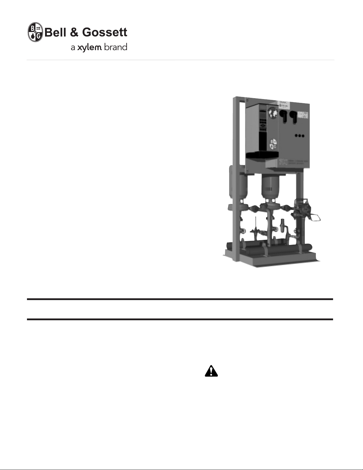
70X Multiple Pump
Pressure Booster Systems
Installation, Operation and
INSTRUCTION MANUAL
S14141B
Service Instructions
INSTALLER: PLEASE LEAVE THIS MANUAL FOR THE OWNER’S USE.
DESCRIPTION
A Bell & Gossett Packaged Pressure Booster System is factory
assembled, tested and shipped as a complete modular unit.
Each Pressure Booster System is tested to internal quality
standards.
The information contained in this manual is intended to assist
operating personnel by providing information on the characteristics of the purchased equipment. It does not relieve the
user of the responsibility to adhere to local codes and ordinances and the use of accepted practices in the installation,
operation and maintenance of this equipment. Further information pertaining to the installation, operation, and maintenance can be found in the I.O.M.s for the specific equipment
provided.
OPERATIONAL LIMITS
See unit nameplate for pump capacity, boost, full load current
draw, and operating voltage. The pump discharge pressure
must not exceed 175 PSI unless specifically designed.
SAFETY
INSTRUCTIONS
This safety alert symbol will be used in this manual and on the
Safety Instruction decal to draw attention to safety related
instructions. When used, the safety alert symbol means
ATTENTION! BECOME ALERT! YOUR SAFETY
FAILURE TO FOLLOW THE INSTRUC
A SAFETY HAZARD!
TION MAY RESULT IN
IS INVOLVED!
Page 2
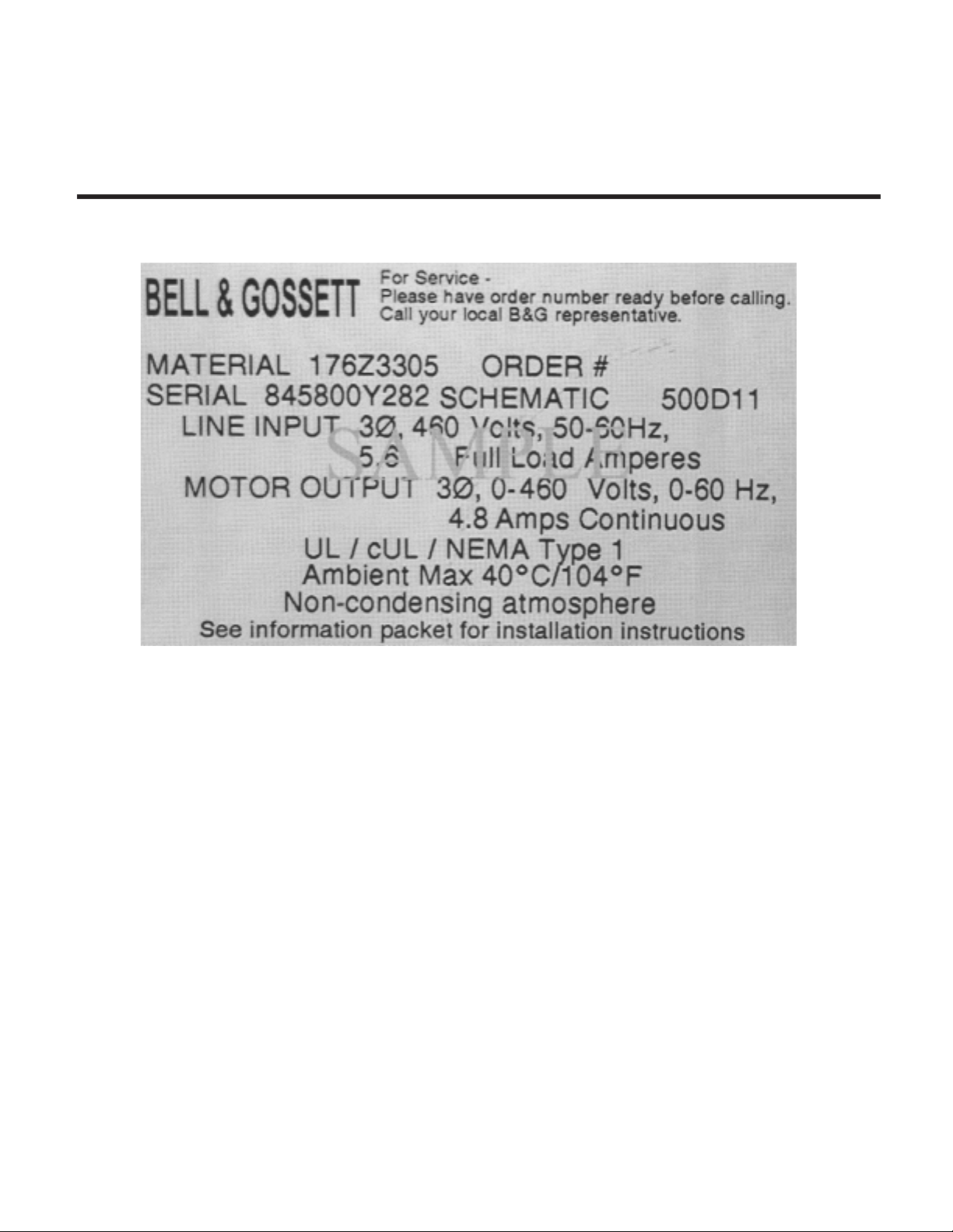
UNIT IDENTIFICATION
The unit nameplate gives identification and rating information
as identified in Figure 1.
UNIT IDENTIFICATION
Records for this unit are kept by the order number (Q______)
and it must therefore be used with all correspondence and
spare parts orders.
PRESSURE BOOSTER SYSTEM
PREFACE
The 70X modular variable speed pressure booster system is
designed to maintain a constant discharge pressure while
minimizing power consumption by combining a variable
speed lead pump with one or two constant speed lag pumps.
This system creates an efficient and practical solution to a
building’s low demand water usage profile. A typical building’s
water demand varies throughout the course of a day and
often a single pump is capable of meeting the demand for
more than half of the day. The 70X controller manages pump
operation to match the wide range of pressure boosting system conditions. The pump controller uses a combination of
kW, pressure and speed to calculate the most efficient points
to stage on and off pumps for operation.
PREFACE
Power consumption is minimized by varying the speed of the
lead pump to satisfy a varying system demand. As the system
demand exceeds the capacity of the lead pump, a constant
speed lag pump is staged on. The constant speed lag pump
operates at full capacity while the lead variable speed pump
adjusts its speed to supplement the system requirement.
When speed demand decreases the lead pump slows down.
While monitoring system pressure, pump speed and power
consumption, the constant speed lag pump is staged off at an
optimal point and the variable speed pump takes over.
FIGURE 1 - Technologic 500X Control Panel Nameplate
2
Page 3

TABLE OF CONTENTS
70X Multiple Pump Pressure Booster Systems
Page
SECTION 1 GENERAL
Purpose of Manual ..............................................................................................................................4
Safety Requirements...........................................................................................................................4
Handling .............................................................................................................................................4
Storage................................................................................................................................................4
Ground Connections ...........................................................................................................................5
Power Wiring .......................................................................................................................................5
Field Connection Diagrams.................................................................................................................5
SECTION 2 INSTALLATION
Location...............................................................................................................................................5
Foundation .........................................................................................................................................5
Leveling ...............................................................................................................................................5
Grouting ..............................................................................................................................................5
Piping Connections .............................................................................................................................5
Misc Connections................................................................................................................................6
Lubrication ..........................................................................................................................................6
Wiring ....................................................................................................................................................
Power Wiring..................................................................................................................................6
Analog Signal Wiring .....................................................................................................................6
Pressure Transmitter Wiring ..........................................................................................................6
Differential Pressure Switch Piping and Wiring .............................................................................7
Low Suction Pressure Switch .......................................................................................................7
..........................................................................................................................................................
SECTION 3 START UP
Putting Unit into Service......................................................................................................................7
Adjustments ........................................................................................................................................7
Thermal Relief Valve .......................................................................................................................7
Pressure Reducing Valve (PRV) .....................................................................................................7
High Pressure PRV ........................................................................................................................7
Differential Pressure Switch ..........................................................................................................7
Low Suction Pressure Switch ........................................................................................................7
SECTION 4 MAINTENANCE
Maintenance (Physical)........................................................................................................................8
..........................................................................................................................................................
APPENDIX A System Piping and Unit Installation – Final Check List .......................................................................9
APPENDIX B Electrical Wiring and Control Settings – Final Check List ...................................................................9
APPENDIX C Procedure for Field Balancing Pressure Reducing Valve ..................................................................10
APPENDIX D Troubleshooting Combination Pressure Reducing and Check Valves ........................................11-12
APPENDIX E Hydropneumatic Tank Field Installation ............................................................................................12
3
Page 4
SECTION 1 - GENERAL
1.1 PURPOSE OF MANUAL
1.1.1 This manual is furnished to acquaint the user
with some of the practical ways to install,
operate, and maintain this unit. Read it carefully before doing any work on your unit and
keep it handy for future reference. This manual
provides general instructions for installation, commissioning and operation to ensure
optimal performance and reliability.
1.1.2 Equipment cannot operate well without proper
care. To keep this unit at top efficiency, follow the recommended installation and servicing procedures outlined in this manual.
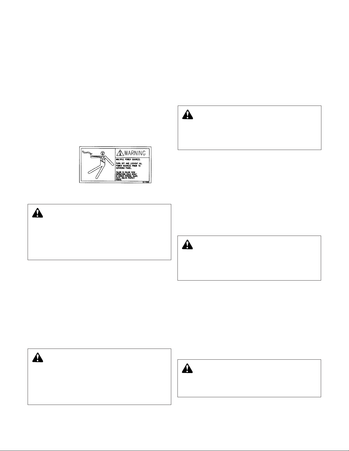
1.1.3 The control panel installed on the pressure
booster system shall have a safety instruction decal (part #S11550 shown below). If the
decal is missing or illegible contact your local
B&G representative for a replacement.
1.2 SAFETY REQUIREMENTS
1.2.1 Motor must have a properly sized starter with
properly sized overload block to provide over
load and undervoltage protection. Ground
fault protection should be sized properly.
1.2.2 Refer to the motor manufacturer’s I.O.M.
(Installation, Operation & Maintenance manual) for
specific installation information.
1.2.3 Even when the motor is stopped, it should be
considered "alive" as long as its controller is
energized. Keep hands away from the output
shaft until the motor has completely stopped
and power is disconnected from the pump
controller.
1.2.4 Motor control equipment and electronic controls are connected to hazardous line volt
ages. When servicing electronic controls,
there will be exposed components at or
above line potential. Extreme care should be
taken to protect against shock. Stand on an
insulating pad and make it a habit to use only
one hand when checking components.
Always use accurate test meters when check
ing electrical components. Always work with
another person in case of an emergency.
Disconnect power when performing maintenance. Be sure equipment is properly grounded.
Wear safety glasses whenever working on electronic control or rotating equipment.
1.3 HANDLING
1.3.1 Care should be taken to prevent damage due
to dropping or jolting when moving the unit.
Inspect the unit thoroughly for damage upon
receipt. Transportation damage should be brought
to the carrier’s attention immediately. Ensure that
sensing lines are free of crimps and kinks.
1.3.2 The unit should be unloaded and handled by qualified personnel. The unit is top heavy due to the
position of the motors. Use the motor eyebolts to
stabilize the unit while lifting to prevent overturning. Do not use the motor eyebolts to lift.
1.4 STORAGE
1.4.1 For periods of storage, the unit should be
covered to prevent corrosion and contamination from dirt. It should be stored in a clean,
dry location to prevent condensation as well
as protected from freezing. After storage,
again check that it is dry before applying
power. Specific component storage instructions must be followed in accordance with
the respective equipment manufacturer’s
recommendations.
WARNING: Make sure the area surrounding the unit
is safe. Be aware of any hazardous conditions that
can exist. Always wear protective glasses and protective
shoes when working with the unit. Do not wear loose fitting
or torn clothing. Remove all jewelry when working.
FAILURE TO FOLLOW THESE INSTRUCTIONS COULD
RESULT IN SERIOUS PERSONAL INJURY, DEATH,
AND/OR PROPERTY DAMAGE.
WARNING:
Motor can start automatically. Keep
hands away from output shaft until motor is completely stopped and input power is removed from the
motor control panel. Lockout main power switch while
working near the motor shaft.
FAILURE TO FOLLOW THESE INSTRUCTIONS COULD
RESULT IN SERIOUS PERSONAL INJURY, DEATH,
AND/OR PROPERTY DAMAGE.
DANGER: Troubleshooting live control panels exposes
personnel to hazardous voltages. Electrical trouble-
shooting must only be done by a qualified electrician.
FAILURE TO FOLLOW THESE INSTRUCTIONS COULD
RESULT IN SERIOUS PERSONAL INJURY, DEATH,
AND/OR PROPERTY DAMAGE.
WARNING: Falling Objects Hazard. Eyebolts or lifting
lugs, if provided, are for lifting only the components
to which they are attached.
FAILURE TO FOLLOW THESE INSTRUCTIONS COULD
RESULT IN SERIOUS PERSONAL INJURY, DEATH,
AND/OR PROPERTY DAMAGE.
CAUTION: Extreme temperatures are to be avoided.
(Below 32ºF and above 110ºF).
FAILURE TO FOLLOW THESE INSTRUCTIONS COULD
RESULT IN PROPERTY DAMAGE AND/OR MODERATE
PERSONAL INJURY.
4
Page 5

1.5 GROUND CONNECTIONS
1.5.1 A grounding terminal is provided for a dedicated
ground wire connection. All provisions of the
National Electrical Code and local codes must be
followed.
1.6 POWER WIRING
1.6.1 Power wire types and sizes must be selected
based upon conformance with the National
Electrical Code and all local codes and restrictions. In addition, only copper (Cu) wire rated for
75°C (minimum) may be used for the power connections. Refer to the input current as listed on
the nameplate on the enclosure door when sizing
wire.
1.7 FIELD CONNECTION DIAGRAMS
1.7.1 Actual equipment manufacturers/models installed
are system specific. Refer to specific manufacturers
Installation, Operation & Maintenance Manuals for
details unique to each component. The following
instruction manual categories are supplied with
the system (if applicable):
Pump
Technologic 500X Pump Controller
(IOM part #176U7761)
Thermal Relief Valve
PRV
Check Valve
1.7.2 The following field connection diagrams
should be reviewed prior to unit installation
and operation.
SECTION 2 - INSTALLATION
2.1 LOCATION
2.1.1 Locate the pumping system in a clean, well
ventilated and properly drained location. It is recommended that the location selected facilitates
ease of inspection, maintenance and service.
Outside installations require protection from freezing.
2.2 FOUNDATION
2.2.1 This unit is built to give you years of service;
install it properly and provide a suitable foundation.
A base of concrete weighing 2-1/2 times the
weight of the unit is recommended. (Check the
shipping ticket for unit weight.) Tie the concrete
pad in with the finished floor. Foundation bolts of
proper size and pipe sleeve should be set in concrete. The pipe sleeve will allow some flexibility in
bolt alignment to match the holes in the base plate.
Allow sufficient bolt length for grout, shims, base
plate, nuts and washers.
2.3 LEVELING
2.3.1 Place the unit on its concrete foundation, support-
ing it with steel wedges or shims totaling 1" in
thickness. These wedges or shims should be put
on both sides of each anchor bolt to provide a
means of leveling the base. After leveling is complete, evenly and firmly tighten the foundation nuts.
Do not fully tighten the bolts until after grouting.
2.4 GROUTING
2.4.1 After the frame has been leveled and securely
bolted to the pad, a good grade of grout should be
installed beneath the base. A suggested mixture
for grout is: one part Portland Cement and two or
three parts plain, sharp sand mixed with water
until it will pour easily. Commercial grout mixtures
with suspended iron particles are available. Wet the
concrete base before pouring grout. Build a strong
form around the foundation to contain grout. Allow
the grout to flow around wedges & shims and
beneath the entire length of the base flange. Allow
the grout to set, usually 48 hours after pouring,
before fully tightening the foundation bolts.
2.5 PIPING CONNECTIONS
2.5.1 Important. Do not install and operate a Bell &
Gossett Pressure Booster in a closed system
unless the system is equipped with properly sized
control devices. Such devices include the use of
properly sized and located pressure relief valves,
compression tanks, pressure control, temperature
controls and flow controls as appropriate. If the
system does not include these devices, consult
the responsible engineer or architect before making pumps operational.
WARNING: Conduit grounds are not adequate. A
separate ground wire must be attached to the
ground lug provided in the enclosure to avoid potential
safety hazards.
FAILURE TO FOLLOW THESE INSTRUCTIONS COULD
RESULT IN SERIOUS PERSONAL INJURY, DEATH,
AND/OR PROPERTY DAMAGE.
Drawing #
Job Specific Print(s)
Job Specific Print(s)
Description
Wiring Diagram
Dimensional Drawing
DANGER: Heavy load, may drop if not lifted properly.
Do not lift the entire unit by component eyebolts.
FAILURE TO FOLLOW THESE INSTRUCTIONS WILL
RESULT IN SERIOUS PERSONAL INJURY, DEATH,
AND/OR PROPERTY DAMAGE.
DANGER: The heating of water and other fluids
causes volumetric expansion. The associated forces
may cause failure of system components and releases of
high temperature fluids. This will be prevented by installing
properly sized and located pressure relief valves and compression tanks.
FAILURE TO FOLLOW THESE INSTRUCTIONS CAN
RESULT IN SERIOUS PROPERTY DAMAGE AND SERIOUS PERSONAL INJURY OR DEATH.
CAUTION: Extreme temperatures are to be avoided
(below 32°F and above 110°F).
FAILURE TO FOLLOW THESE INSTRUCTIONS COULD
RESULT IN PROPERTY DAMAGE AND/OR MODERATE
PERSONAL INJURY.
5
Page 6

2.5.2 After hydrotesting, drain plugs are removed, to
facilitate system drainage, placed in a cloth bag
and secured to the unit. Drain plugs shall be reinstalled prior to filling the system with fluid. Inspect
all unit piping connections. Joints may also
become loose during transit due to vibration and
shock. All joints are to be checked for tightness.
Flanged joints should be checked for proper torque
of all flange bolts prior to filling the system with fluid.
2.5.3 Make all necessary system piping connections. Be
aware that connecting dissimilar metals to the
headers can lead to corrosion damage due to galvanic corrosion. The rate of corrosion is dependant
on various factors some of which are; the potential
between the dissimilar metals, electrolyte conductivity, geometry and area of the metals. Dielectric
connections are recommended between dissimilar
metals at the header connection. Be sure to eliminate any pipe strain on the unit. Support all pipes
independently by use of pipe hangers near the unit.
DO NOT ATTEMPT TO FORCE THE SUCTION OR
DISCHARGE LINES INTO POSITION. Refer to
assembly drawing for customer piping connections.
2.5.4 The maximum suction pressure shall not exceed
150 psi. Dead head pressure plus suction pressure
shall not exceed 175 psi.
2.5.5 As a rule, ordinary wire or band hangers are not
adequate to maintain alignment. It is very important to provide a strong, rigid support for the suction line. A saddle hanger is recommended.
2.5.6 For critical installations, equipment for absorbing
expansion and vibration should be installed at the
inlet and outlet connections of the unit.
2.5.7 Eccentric increasers can be used in the suction pipe
line when increasing the pipe size, with straight
sides of increaser on top to eliminate air pockets.
2.5.8 On an open system with a suction lift, a foot valve
of equal or greater area than the pump suction is
recommended. Prevent clogging by using a strainer
at the suction inlet next to the foot valve. The
strainer should have an area three times that of the
suction pipe. Provisions must be made to prime
the pump suction piping on start up. Do not start
the pump unless all suction piping is full of water.
2.6 MISCELLANOUS CONNECTIONS
2.6.1 Hydro-Pneumatic Tank (optional): The tank is supplied mounted on a separate base for ease of handling, unit installation and space considerations.
Mount the tank adjacent to the unit. A union connection is provided to allow quick connection to
the unit. The tank is intended to maintain system
pressure due to minor system leaks and periods of
low demand.
2.6.2 Pre-charge the Hydro Pneumatic tank prior to filling the system. The tank should be air charged to
the pump restart pressure minus 1 psi. If the tank
is located above the booster, the precharge pressure is calculated by pump restart pressure minus
tank elevation above pressure booster (psi) minus
1 psi.
2.6.3 For tanks supplied by others, refer to appendix E
for tank installation.
2.7 LUBRICATION
2.7.1 Before starting, all pumps and motors should be
checked for proper lubrication.
2.8 WIRING
2.8.1 Refer to the controller instruction manual for electrical connection, set-up and troubleshooting.
2.9 POWER WIRING
2.9.1 The Control Panel is designed to operate at a specific voltage as indicated on the control panel
nameplate. Verify proper transformer primary
wiring per the job-specific wiring diagram. Check
power leads in accordance with wiring diagram
enclosed in control cabinet. The voltage tolerance
is +10%/-10%.
2.10 ANALOG SIGNAL WIRING
2.10.1 If installing the panel on an existing system, twisted
pair shielded cable (#22 AWG, Belden type 8762,
Alpha #2411 or equal) should be installed for the
DC control wiring. The shield must be terminated
in the control panel. Do not connect the shield at
the other end of the cable! Insulate the shield so
that no electrical connection is made at the other
end of the cable. A twisted pair of #22 AWG conductors (Belden 8442 or equal) can be used in
place of shielded cable. The cable length must be
limited to 3000 feet for #22 AWG wire.
2.11 PRESSURE TRANSMITTER WIRING
(4-20 mA Analog Signals)
2.11.1 (Optional) A pressure transmitter, if supplied with
the booster unit, is installed at the discharge
header. Otherwise, a pressure transmitter is supplied loose. It is recommended that the sensor be
installed in the zone furthest away or at the most
critical zone. Refer to wiring diagram for exact terminal locations.
DANGER: Electrical shock hazard. Inspect all
electrical connections prior to powering the unit.
Wiring connections must be made by a qualified electrician
in accordance with all applicable codes, ordinances, and
good practices.
FAILURE TO FOLLOW THESE INSTRUCTIONS COULD
RESULT IN SERIOUS PERSONAL INJURY, DEATH,
AND/OR PROPERTY DAMAGE.
6
CAUTION: Failure to reinstall drain plugs, check all
joints for tightness and flange bolts for proper torque
could result in leaks and/or flooding.
FAILURE TO FOLLOW THESE INSTRUCTIONS COULD
RESULT IN PROPERTY DAMAGE AND/OR MODERATE
PERSONAL INJURY.
Page 7

2.12 DIFFERENTIAL PRESSURE SWITCH
PIPING AND WIRING
2.12.1 (Optional) Differential pressure switches are available to sense the increase in pressure between
the pump suction and discharge gauge taps that
is used to determine whether a pump is running.
The switch is wired normally closed to the control
panel. Refer to wiring diagram for exact terminal
locations. (Differential pressure switch may
require field calibration.) Ref-3.6.1.
2.13 LOW SUCTION PRESSURE
2.13.1 (Optional) Low suction pressure switch is available and intended to stop pump operation when
an insufficient pump suction condition exists. The
switch is wired normally closed to the control
panel. Refer to wiring diagram for exact terminal
locations.
SECTION 3 - START UP
3.1 PUTTING THE UNIT INTO SERVICE
3.1.1 After package is installed and foundation bolts
are tightened, check pump alignment. Refer to
specific pump Installation, Operation &
Maintenance manual for alignment procedures.
3.1.2 Fill system with fluid after reading the cautions in
the piping connection section of this manual.
3.1.3 Vent all high points in the piping system to
removed trapped air.
3.1.4 Before starting all pumps and drivers should be
checked for proper lubrication.
3.1.5 Piping should be clean and flushed prior to
operation.
3.1.6 PUMP ROTATION, 3 PHASE MOTORS ONLY
3.1.7 With the disconnect switch engaged to the "ON"
position, momentarily start and stop each motor.
Observe the pump shaft rotation.
3.1.8 If incorrect, turn the main disconnect off and inter-
change any two wire leads leaving the starter overload block and going to the motor.
3.1.9 Unit is now ready for operation.
3.2 ADJUSTMENTS
3.2.1 Final adjustments on the following adjustable
devices shall be made to match exact system
requirements.
3.3 THERMAL RELIEF VALVE
3.3.1 A thermal relief valve is installed on the discharge
header to prevent potentially dangerous thermal
pressure buildup. The valve automatically opens
on temperature increase and closes on temperature decrease. This valve acts as a safety device
and should never be removed or plugged. It is factory set to open and discharge when the water
temperature in the discharge header reaches
125°F. The 3/8" NPT opening of this valve shall be
piped to a floor drain in accordance with local codes.
3.3.2 To raise the valve opening point, turn the adjustment screw counter-clockwise; to lower the valve
opening point, turn the screw clockwise. The closing point is non adjustable, approximately 3 to 5º F
below opening point.
3.3.3 To flush valve manually, insert a screwdriver under
each side of the lower spring guide. Pry both guide
and spring away from body to open valve.
3.3.4 After long periods of operation, valve seat and disc
may become worn or pitted, allowing leakage
through valve in closed position. Internal parts can
be replace if desired.
3.4 PRESSURE REDUCING VALVE (PRV)
3.4.1 The PRV is used to maintain a desirable pressure
at the discharge header. The PRV is preset at the
factory to the exact system requirements. If further adjustments are necessary refer to the PRV
instruction manual.
3.5 High PRESSURE PRV (If Required)
3.5.1 On systems where the system pressure reaches
above 135 psi a high pressure PRV is required to
protect the thermal relief valve from exceeding its
pressure rating. The high pressure PRV has an
adjustable range from 30 to 300 psi and is manufacturer set at 60 psi. No further adjustments are
recommended.
3.6 DIFFERENTIAL PRESSURE SWITCH (Optional)
3.6.1 The differential pressure switch has a range from
1/2-36 psid and is manufacturer set at 18 psid. It is
recommended that the setting be adjusted to 2 psi
less than the minimum pump differential pressure
to avoid nuisance alarms. The minimum pump differential pressure is equal to the pump discharge
pressure at minimum speed minus suction pressure. To adjust the setting, remove the cover. To
decrease the operating point, face the switch,
place a flat bladed screwdriver in the slots of the
main range adjustment nut and rotate from left to
right. For further information refer to switch
instruction manual supplied with the unit.
3.7 LOW SUCTION PRESSURE SWITCH (Optional)
3.7.1 Manufacturer set at 40 psi. It is recommended that
the setting be adjusted to 10 psi below rated suction pressure. To adjust the setting, remove the
cover. Turn the reference dial to the desired set
point by aligning setting on dial with the dowel pin.
WARNING: Rotating shafts can catch loose clothing.
Do not operate the pump without all guards in place.
FAILURE TO FOLLOW THESE INSTRUCTIONS COULD
RESULT IN SERIOUS PERSONAL INJURY, DEATH,
AND/OR PROPERTY DAMAGE.
DANGER: High Voltage 3 phase power can kill.
Disconnect and lockout power prior to servicing unit.
FAILURE TO FOLLOW THESE INSTRUCTIONS COULD
RESULT IN SERIOUS PERSONAL INJURY, DEATH,
AND/OR PROPERTY DAMAGE.
CAUTION: Seal Damage may occur. Do not run
pumps dry. Fill and vent the pump volute prior to
operation.
FAILURE TO FOLLOW THESE INSTRUCTIONS COULD
RESULT IN PROPERTY DAMAGE AND/OR MODERATE
PERSONAL INJURY.
7
Page 8

SECTION 4 - MAINTENANCE
4.1 MAINTENANCE (PHYSICAL)
4.1.1 Refer to specific component IOM for maintenance
information.
4.1.2 Mechanical - A Series 1531 pump was lubricated
at the factory. Future lubrication should be according to the motor manufacturer’s instructions.
4.1.3 A Series 1510 pump requires regreasing after
every 2500 hours of operation or every six months
whichever occurs first. Lubricate motor per motor
manufacturer’s instruction.
4.1.4 If there is a danger of freezing, drain the pump.
Inspect pump and system piping regularly.
4.1.5 For leaky seals or gaskets and loose or damaged
components, replace or repair as required.
For more instruction on the B&G pumps see the following
manuals: 1510 (IOM Part #P81673) or 1531 (IOM Part
#P81567).
8
Page 9

9
APPENDIX A
____ 1. Is the unit base properly leveled, grouted and
secured?
____ 2. Are all lubrication points properly lubricated?
____ 3. Is the outlet side of the high temperature regulat-
ing valve connected to the drain with tubing or
pipe size 3/8" or greater?
____ 4. Is the shut-off valve to the pressure transmitter(s)
open?
____ 5. Is the shut-off valve to the pump suction open?
____ 6. Is the shut-off valve on the discharge line open?
____ 7. Is the bypass valve, if used, closed? This valve
may be left open if a check valve is installed in
series with it.
____ 8. Are the stop cocks for the check feature on the
PRV open? They must never be completely closed
during normal operation. Throttle cock if check
slamming is noted.
____ 9. Is the piping properly supported so as to prevent
strains on unit?
____ 10. Is the system, including the pumps and PRV’s,
purged of debris and air?
____ 11. Is the Hydro Pneumatic tank charged properly?
The tank must be empty of water when checking
the air charge.
____ 12. Are the bleed valves at the high temperature valve
header open?
APPENDIX B
APPENDIX B
____ 1. Does the feeder line voltage correspond to the unit
voltage? Check the unit nameplate or motor terminal connection.
____ 2. Are the feeder wires correctly sized for the load?
____ 3. Are the fuses correctly sized? They must not
exceed 1.75 times the full load current of the
motor. Usual sizing is 1.15 to 1.5 times the full
load current.
____ 4. Is the unit properly grounded?
____ 5. Have all the power terminals in the control panel
been checked for tightness? This is imperative
since stranded wires tend to "flow" and become
loose after initial installation.
____ 6. Are motor overloads set properly? Set the over-
loads to FLA as a minimum and SF x FLA as a
maximum.
____ 7. Is the pump rotation correct?
CAUTION: Seal Damage may occur. Do not run
pumps dry. Fill and vent the pump volute prior to
operation.
FAILURE TO FOLLOW THESE INSTRUCTIONS COULD
RESULT IN PROPERTY DAMAGE AND/OR MODERATE
PERSONAL INJURY.
WARNING: Electrical shock hazard. Inspect all
electrical connections prior to powering the unit.
Wiring connections must be made by a qualified electrician
in accordance with all applicable codes, ordinances, and
good practices.
FAILURE TO FOLLOW THESE INSTRUCTIONS COULD
RESULT IN SERIOUS PERSONAL INJURY, DEATH,
AND/OR PROPERTY DAMAGE.
WARNING: Conduit grounds are not adequate. A
separate ground wire must be attached to the ground
lug provided in the enclosure to avoid potential safety
hazards.
FAILURE TO FOLLOW THESE INSTRUCTIONS COULD
RESULT IN SERIOUS PERSONAL INJURY, DEATH,
AND/OR PROPERTY DAMAGE.
DANGER: High Voltage 3 phase power can kill.
Disconnect and lockout power prior to servicing unit.
FAILURE TO FOLLOW THESE INSTRUCTIONS WILL
RESULT IN SERIOUS PERSONAL INJURY, DEATH,
AND/OR PROPERTY DAMAGE.
ELECTRICAL WIRING AND CONTROL SETTINGS - FINAL CHECK LIST
SYSTEM PIPING AND UNIT INSTALLATION - FINAL CHECK LIST
Page 10

10
APPENDIX C
PROCEDURE FOR FIELD BALANCING PRESSURE REDUCING VALVE
COMBINATION PRESSURE REDUCING AND CHECK VALVE
Item Name Primary Function
1 Strainer Prevents orifice from clogging
2 Check Valve Prevents backflow from top of diaphragm when pumping stops.
3 Orifice Provides metered water flow to top-side of diaphragm.
4 Opening Speed Flow Control Dampens pressure fluctuations (slow opening).
5 CRD Pilot PRV.
6 Gauge Optional location for system pressure gauge.
7 Cock Adjustment for rate of closure (non-slam).
8 Check Valve Prevents backflow from top of diapgragm during normal operation.
9 Vent Bleeds air from top of diaphragm.
10 Diaphragm Divides inlet and outlet pressures.
Figure 2
1.0 Pressure Reducing valve (PRV) Adjustment
1.1 The pressure reducing valves are "factory set". If
needed, the following items should be checked
first before any attempt is made to change the
setting:
a) Does the desired system pressure correspond
to the pressure indicated on the nameplate?
b) Is the suction pressure equal to or higher than
the pressure indicated on the nameplate?
c) Is the demand (GPM) within the capacity indi-
cated on the nameplate?
d) Has the PRV been properly vented?
1.2 Any deviation from the above conditions will prevent the unit from operating at the factory (nameplate) settings.
1.3 To adjust the PRV place the pump in manual operation per Technologic 500X instruction manual.
With the pump now running, slowly close the main
gate valve downstream of the discharge header
allowing a trickle of water to flow through it. Read
the system pressure on the display. It should read
3 or 4 psi higher than the desired system pres-
sure. If not, remove the protective cap on the pilot
control valve and loosen the jam nut on the
adjusting stem of the PRV. Slowly turn the stem
clockwise to increase the delivery pressure and
counter clockwise to decrease pressure. (Note
that a pilot valve furnished for a 20 to 300 psi
range will change the main valve setting approximately 28 psi for each full turn of the adjusting
screw.) Set the screw so the system display reads
3 to 4 psi higher than the desired system pressure.
1.4 Open the gate valve fully. If feasible, draw between 50 to 80% of the designed pump capacity
to recheck valve setting. The display should now
read the desired system pressure. Tighten jam
nut and replace cap.
1.5 Repeat the above procedure for all pump and
valve combinations as required.
1.6 The CV Flow Control Valve (opening speed control) may require field adjustment if pressure hunting occurs. Normal setting of the valve is from 4 to
7 turns open. Never open more than 8 turns.
Page 11

TROUBLESHOOTING COMBINATION PRESSURE REDUCING AND CHECK VALVES
11
DANGER: Troubleshooting live control panels exposes
personnel to hazardous voltages. Electrical trouble-
shooting must only be done by a qualified electrician.
FAILURE TO FOLLOW THESE INSTRUCTIONS COULD
RESULT IN SERIOUS PERSONAL INJURY, DEATH,
AND/OR PROPERTY DAMAGE.
APPENDIX D
1.0 System Pressure Higher than Desired Set Point
1.1 Primary Causes
a) Insufficient pressure on top side of diaphragm.
b) Leakage through main valve seat.
c) Pressure build-up due to thermal expansion,
such as caused by volumetric expansion of the
water in a heater connected to the system side
of the PRV.
d) Inaccurate system pressure signal.
1.2 Tests and Remedies (see Figure 2 for item numbers)
a) Install gauge, install on CRD (Item 6), if
necessary.
b) Vent air from air vent (Item 9) and from other
high points of PRV trim. Valve cover bolts may
have to be loosened on some units with PRV
mounted horizontally.
c) Check CRD set point adjustment.
d) Close stop cock (Item 7) in check line. If PRV
now operates properly, clean or replace adja-
cent check valve (Item 8).
e) Inspect CRD (Item 5) disc and seat for proper
seating.
f) Inspect strainer (Item 1) that the screen is clean.
g) Inspect orifice (Item 3) that it is not clogged.
h) Plug outlet side of CRD. If main valve closed
tight, the problem most likely is in the CRD.
Replace same. If the main valve does not close
tight, disassemble it for inspection. Check for
scored seat.
2.0 System Pressure Lower than Desired Set Point
2.1 Primary Causes
a) Excessive pressure on top side of diaphragm.
b) Suction pressure below design conditions
(check nameplate on panel door for design
conditions).
c) Desired system pressure is higher than design
condition (check panel nameplate).
d) Flow Rate is greater than design condition.
e) Inaccurate system pressure signal.
2.2 Tests and Remedies (see Figure 2 for item numbers)
a) Install gauge, install on CRD (Item 6), if
necessary.
b) Vent air from air vent and all high points.
c) CRD disc guide or yoke binding.
d) Check motor amps. If greater than full load
amps (motor nameplates), flow rate may be
greater than design.
e) Leak into upper diaphragm chamber. Close
stop cock (Item 7) and remove a connection
between the flow control valve (Item 4) and the
PRV valve cover. Plug the flow control side.
Open pump suction valve and start pump. If
water emits from the valve cover plate, there is
a leak passing the diaphragm into the upper
chamber.
f) Remove valve cover plate for inspection.
Remove "cancerous" buildups which may prevent diaphragm from lifting fully. Check for
binding of valve stem assembly.
g) Opening speed control valve (Item 4)
clogged in restricted flow mode (out of PRV
valve cover).
h) Orifice (Item 3) missing. The orifice fitting identi-
cal in appearance to a flare to MPT adapter,
therefore may have been inadvertently replaced
or misplaced during valve service.
i) Check pump discharge pressure. Does it corre-
spond to the TDH curve?
3.0 System Pressure Slow to Recover from Under
Pressure to Set Point
3.1 Primary Causes
a) Pressure above the diaphragm is not being
removed quickly enough.
b) Mechanical binding in main PRV or CRD pilot
valve.
c) Excessive suction supply line pressure drop.
3.2 Remedies (see Figure 2 for item numbers)
a) Any of the items of 2.2 may be a contributing
factor.
b) Readjust flow control valve (Item 4) to less
restrictive setting, turn counter clockwise.
NOTE: Forcing the stem too far CCW will shear
the stem snap ring and cause the stem to blow
out. Recommend that the stem be initially turned
CW, noting the number of turns required to seat
the stem, then backing it out CCW a few more
turns than the original setting. The maximum
CCW setting is about 9 turns.
4.0 System Pressure Overshoots Greatly and Slow to
Recover to Set Point
4.1 Primary Causes
a) Pressure above the diaphragm is not being
applied soon enough.
b) Mechanical binding in main PRV or CRD pilot
valve.
c) Leaky seat in main PRV or CRD valves.
d) Excessive suction supply line pressure drop.
e) System side surge (water hammer) due to
sudden closure of a quick opening valve.
f) Strainer (Item 1) clogged.
4.2 Remedies (see Figure 2 for item numbers)
a) Any of the items of 1.2 may be contributing
factors.
b) Install larger orifice (Item 3).
Page 12

5.0 PRV Does Not Close (Check) on
Pump Shut Down
5.1 Primary Causes
a) Insufficient pressure on top of diaphragm.
b) Leak through main valve seat or diaphragm
assembly.
5.2 Remedies (see Figure 2 for item numbers)
a) Stop cock (Item 7) closed preventing pressure
from reaching valve cover.
b) Leaking check valve (Item 2).
c) To determine whether leak is in main valve seat
or diaphragm assembly:
1. Disconnect line between flow control valve
(Item 4) and valve cover.
2. Plug flow control side.
3. Install pressure gauge in valve cover.
4. Remove vent plug in pump volute to drain
inlet side of PRV.
5. Apply pressure to top side of diaphragm by
opening shutoff valve on outlet side of PRV.
6. Read gauge pressure.
7. Close stop cock (Item 7).
If gauge pressure fails, there is a leak in the diaphragm assembly. This test, however, does not
indicate whether the seat is also leaking.
6.0 PRV Slams Shut on Pump Shut Down
6.1 Primary Causes
a) Too rapid buildup of pressure on top of
diaphragm.
b) Main valve assembly binding.
c) Check valve (Item 2) sticking open momentarily
6.2 Remedies (see Figure 2 for item numbers)
a) Throttle stop cock (Item 7).
NOTE: Closing this stop cock will completely
prevent PRV from functioning as a check valve.
b) Vent air from PRV (see 1.2b).
APPENDIX E
HYDRO-PNEUMATIC TANK FIELD INSTALLATION
Figure 3
Xylem Inc.
10661 Newkirk Street
Dallas, TX 75220
Phone: (469) 221-1200
Fax: (214) 357-5861
www.xyleminc.com/brands/bellgossett
Bell & Gossett is a trademark of Xylem Inc. or one of its subsidiaries.
© 2012 Xylem Inc. S14141B August 2012
 Loading...