

Page 1
VARIABLE SPEED PUMPING SYSTEMS
INSTRUCTION MANUAL
Technologic®5500 Series
INSTRUCTION MANUAL
S13641B
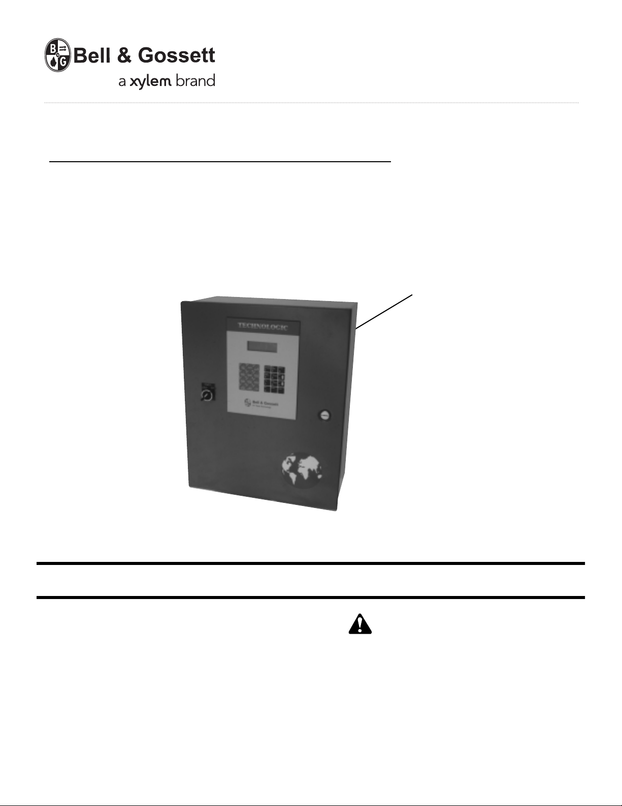
Pump Controller
WARNING LABEL PART #S11550
INSTALLED IN THIS LOCATION.
IF MISSING IT MUST BE REPLACED.
INSTALLER: PLEASE LEAVE THIS MANUAL FOR THE OWNER’S USE.
DESCRIPTION
Microprocessor based dedicated pump controller for variable
volume pumping systems. The control panel consists of the
following components: microprocessor, operator interface
with 4 line display and membrane key pad, 24 VDC power
supply. Multi-pinned connecting cables for connection to
bypass panels are available as options.
OPERATIONAL LIMITS
See the control panel nameplate for operating voltage, current
draw, as well as information on the equpiment to be connected to the control panel.
This safety alert symbol will be used in this manual and on the
Technologic 5500 Safety Instruction decal to draw attention to
safety related instructions. When used, the safety alert symbol
means ATTENTION! BECOME ALERT! YOUR SAFETY IS
INVOLVED! FAILURE TO FOLLOW THE INSTRUCTION
MAY RESULT IN A SAFETY HAZARD!
SAFETY
INSTRUCTIONS
Page 2

2
Preface
The following manual describes the new microprocessor based Technologic 5500 Controller. This unit is in
the tradition of the other members of the Technologic
Control Panels as it incorporates many original, novel,
and proprietary features that may only be found on
B&G controllers. Some of these features require special emphasis here.
The controller is best described as a specific purpose
programmable pump controller. This means that the
hardware and software have been created for the control and diagnostics of pumps with consideration for
their inherent characteristics. This results in an optimum
pump controller without the cost of general purpose
control hardware. Software is dedicated and established for the unit only after extensive testing. Changes
to this software are not taken lightly and must pass
rigid version control.
The controller has the unique analog input protection
of other members of the control family. In the event of
a short circuit condition the current limit circuitry prevents failure of the analog input components.
This new controller has standard manual bypass
switches when a Bell & Gossett automatic bypass is
supplied. The manual bypass switches allow the user
to de-energize the programmable logic controller and
take manual control of the pumping system. This is
helpful during system startup to confirm pump rotation
and to purge air from the system prior to switching to
automatic control.
Page 3

3
SECTION 1 - GENERAL Page
Purpose of Manual . . . . . . . . . . . . . . . . . . . . . . . . . . . . . . . . . . . . . . . . . . . . . . . . . . . . . . . . . . . . . . 5
Safety Instruction . . . . . . . . . . . . . . . . . . . . . . . . . . . . . . . . . . . . . . . . . . . . . . . . . . . . . . . . . . . . . . . 5
Additional Safety Requirement . . . . . . . . . . . . . . . . . . . . . . . . . . . . . . . . . . . . . . . . . . . . . . . . . . . . . 5
Storage . . . . . . . . . . . . . . . . . . . . . . . . . . . . . . . . . . . . . . . . . . . . . . . . . . . . . . . . . . . . . . . . . . . . . . . 6
Handling . . . . . . . . . . . . . . . . . . . . . . . . . . . . . . . . . . . . . . . . . . . . . . . . . . . . . . . . . . . . . . . . . . . . . . 6
Temperature and Ventilation . . . . . . . . . . . . . . . . . . . . . . . . . . . . . . . . . . . . . . . . . . . . . . . . . . . . . . . 6
Input Voltage . . . . . . . . . . . . . . . . . . . . . . . . . . . . . . . . . . . . . . . . . . . . . . . . . . . . . . . . . . . . . . . . . . . 6
Ground Connections . . . . . . . . . . . . . . . . . . . . . . . . . . . . . . . . . . . . . . . . . . . . . . . . . . . . . . . . . . . . . 6
Power Wiring . . . . . . . . . . . . . . . . . . . . . . . . . . . . . . . . . . . . . . . . . . . . . . . . . . . . . . . . . . . . . . . . . . . 6
Output/Motor Disconnect . . . . . . . . . . . . . . . . . . . . . . . . . . . . . . . . . . . . . . . . . . . . . . . . . . . . . . . . . 6
Analog Signals . . . . . . . . . . . . . . . . . . . . . . . . . . . . . . . . . . . . . . . . . . . . . . . . . . . . . . . . . . . . . . . . . . 7
Field Connection Diagrams . . . . . . . . . . . . . . . . . . . . . . . . . . . . . . . . . . . . . . . . . . . . . . . . . . . . . . . . 7
Sensor & Control Wiring . . . . . . . . . . . . . . . . . . . . . . . . . . . . . . . . . . . . . . . . . . . . . . . . . . . . . . . . . . 7
SECTION 2 - INSTALLATION & STARTUP
Location . . . . . . . . . . . . . . . . . . . . . . . . . . . . . . . . . . . . . . . . . . . . . . . . . . . . . . . . . . . . . . . . . . . . . . . 8
Installation . . . . . . . . . . . . . . . . . . . . . . . . . . . . . . . . . . . . . . . . . . . . . . . . . . . . . . . . . . . . . . . . . . . . . 8
Putting Unit into Service . . . . . . . . . . . . . . . . . . . . . . . . . . . . . . . . . . . . . . . . . . . . . . . . . . . . . . . . . . 9
SECTION 3 - SETUP AND FEATURES
General Notes . . . . . . . . . . . . . . . . . . . . . . . . . . . . . . . . . . . . . . . . . . . . . . . . . . . . . . . . . . . . . . . . . . 9
Power-Up . . . . . . . . . . . . . . . . . . . . . . . . . . . . . . . . . . . . . . . . . . . . . . . . . . . . . . . . . . . . . . . . . . . . . 9
Setup . . . . . . . . . . . . . . . . . . . . . . . . . . . . . . . . . . . . . . . . . . . . . . . . . . . . . . . . . . . . . . . . . . . . . . . . . 9
Sensor Setup . . . . . . . . . . . . . . . . . . . . . . . . . . . . . . . . . . . . . . . . . . . . . . . . . . . . . . . . . . . . . . . . . . . 10
Pump Setup . . . . . . . . . . . . . . . . . . . . . . . . . . . . . . . . . . . . . . . . . . . . . . . . . . . . . . . . . . . . . . . . . . . 11
System Setup . . . . . . . . . . . . . . . . . . . . . . . . . . . . . . . . . . . . . . . . . . . . . . . . . . . . . . . . . . . . . . . . . . 12
Stage/Destage Setup . . . . . . . . . . . . . . . . . . . . . . . . . . . . . . . . . . . . . . . . . . . . . . . . . . . . . . . . . . . . 12
PID Setup . . . . . . . . . . . . . . . . . . . . . . . . . . . . . . . . . . . . . . . . . . . . . . . . . . . . . . . . . . . . . . . . . . . . . 14
Alarm Setup . . . . . . . . . . . . . . . . . . . . . . . . . . . . . . . . . . . . . . . . . . . . . . . . . . . . . . . . . . . . . . . . . . . . 14
Alternation Setup . . . . . . . . . . . . . . . . . . . . . . . . . . . . . . . . . . . . . . . . . . . . . . . . . . . . . . . . . . . . . . . . 15
Bypass Setup . . . . . . . . . . . . . . . . . . . . . . . . . . . . . . . . . . . . . . . . . . . . . . . . . . . . . . . . . . . . . . . . . . 15
AFD Setup . . . . . . . . . . . . . . . . . . . . . . . . . . . . . . . . . . . . . . . . . . . . . . . . . . . . . . . . . . . . . . . . . . . . . 16
Date/Time Setup . . . . . . . . . . . . . . . . . . . . . . . . . . . . . . . . . . . . . . . . . . . . . . . . . . . . . . . . . . . . . . . . 17
Password Setup . . . . . . . . . . . . . . . . . . . . . . . . . . . . . . . . . . . . . . . . . . . . . . . . . . . . . . . . . . . . . . . . 17
I/O Setup . . . . . . . . . . . . . . . . . . . . . . . . . . . . . . . . . . . . . . . . . . . . . . . . . . . . . . . . . . . . . . . . . . . . . . 18
Communication Setup . . . . . . . . . . . . . . . . . . . . . . . . . . . . . . . . . . . . . . . . . . . . . . . . . . . . . . . . . . . 19
Special Functions Setup . . . . . . . . . . . . . . . . . . . . . . . . . . . . . . . . . . . . . . . . . . . . . . . . . . . . . . . . . . 20
Testing Inputs & Outputs . . . . . . . . . . . . . . . . . . . . . . . . . . . . . . . . . . . . . . . . . . . . . . . . . . . . . . . . . 22
Index
Page 4

4
INDEX (continued)
SECTION 4 - TYPES OF PROGRAMS Page
AO . . . . . . . . . . . . . . . . . . . . . . . . . . . . . . . . . . . . . . . . . . . . . . . . . . . . . . . . . . . . . . . . . . . . . . . . . . 24
A1 . . . . . . . . . . . . . . . . . . . . . . . . . . . . . . . . . . . . . . . . . . . . . . . . . . . . . . . . . . . . . . . . . . . . . . . . . . 25
B3 . . . . . . . . . . . . . . . . . . . . . . . . . . . . . . . . . . . . . . . . . . . . . . . . . . . . . . . . . . . . . . . . . . . . . . . . . . 25
C0 . . . . . . . . . . . . . . . . . . . . . . . . . . . . . . . . . . . . . . . . . . . . . . . . . . . . . . . . . . . . . . . . . . . . . . . . . . 26
D0 . . . . . . . . . . . . . . . . . . . . . . . . . . . . . . . . . . . . . . . . . . . . . . . . . . . . . . . . . . . . . . . . . . . . . . . . . . 26
D4 . . . . . . . . . . . . . . . . . . . . . . . . . . . . . . . . . . . . . . . . . . . . . . . . . . . . . . . . . . . . . . . . . . . . . . . . . . 27
Special Programs . . . . . . . . . . . . . . . . . . . . . . . . . . . . . . . . . . . . . . . . . . . . . . . . . . . . . . . . . . . . . . . 27
Pump Rotation . . . . . . . . . . . . . . . . . . . . . . . . . . . . . . . . . . . . . . . . . . . . . . . . . . . . . . . . . . . . . . . . . 27
Manual Bypass . . . . . . . . . . . . . . . . . . . . . . . . . . . . . . . . . . . . . . . . . . . . . . . . . . . . . . . . . . . . . . . . . 28
Hand Manual Speed Control . . . . . . . . . . . . . . . . . . . . . . . . . . . . . . . . . . . . . . . . . . . . . . . . . . . . . . . 28
Hand Bypass . . . . . . . . . . . . . . . . . . . . . . . . . . . . . . . . . . . . . . . . . . . . . . . . . . . . . . . . . . . . . . . . . . . 28
Setpoint Modification . . . . . . . . . . . . . . . . . . . . . . . . . . . . . . . . . . . . . . . . . . . . . . . . . . . . . . . . . . . . 28
Process Variable Monitoring . . . . . . . . . . . . . . . . . . . . . . . . . . . . . . . . . . . . . . . . . . . . . . . . . . . . . . . 29
Alarms . . . . . . . . . . . . . . . . . . . . . . . . . . . . . . . . . . . . . . . . . . . . . . . . . . . . . . . . . . . . . . . . . . . . . . . . 29
SECTION 5 - MAINTENANCE
Preface . . . . . . . . . . . . . . . . . . . . . . . . . . . . . . . . . . . . . . . . . . . . . . . . . . . . . . . . . . . . . . . . . . . . . . . 30
Technical Overview . . . . . . . . . . . . . . . . . . . . . . . . . . . . . . . . . . . . . . . . . . . . . . . . . . . . . . . . . . . . . . 30
Digital Inputs . . . . . . . . . . . . . . . . . . . . . . . . . . . . . . . . . . . . . . . . . . . . . . . . . . . . . . . . . . . . . . . . . . . 30
Digital Outputs . . . . . . . . . . . . . . . . . . . . . . . . . . . . . . . . . . . . . . . . . . . . . . . . . . . . . . . . . . . . . . . . . 30
Analog Inputs . . . . . . . . . . . . . . . . . . . . . . . . . . . . . . . . . . . . . . . . . . . . . . . . . . . . . . . . . . . . . . . . . . 30
Memory . . . . . . . . . . . . . . . . . . . . . . . . . . . . . . . . . . . . . . . . . . . . . . . . . . . . . . . . . . . . . . . . . . . . . . . 30
CPU . . . . . . . . . . . . . . . . . . . . . . . . . . . . . . . . . . . . . . . . . . . . . . . . . . . . . . . . . . . . . . . . . . . . . . . . . . 30
Power Supply . . . . . . . . . . . . . . . . . . . . . . . . . . . . . . . . . . . . . . . . . . . . . . . . . . . . . . . . . . . . . . . . . . 30
Protection . . . . . . . . . . . . . . . . . . . . . . . . . . . . . . . . . . . . . . . . . . . . . . . . . . . . . . . . . . . . . . . . . . . . . 31
Instruments and Their Use . . . . . . . . . . . . . . . . . . . . . . . . . . . . . . . . . . . . . . . . . . . . . . . . . . . . . . . . 31
Field Repair . . . . . . . . . . . . . . . . . . . . . . . . . . . . . . . . . . . . . . . . . . . . . . . . . . . . . . . . . . . . . . . . . . . . 31
Program Updating . . . . . . . . . . . . . . . . . . . . . . . . . . . . . . . . . . . . . . . . . . . . . . . . . . . . . . . . . . . . . . . 31
Program Type and Version Number . . . . . . . . . . . . . . . . . . . . . . . . . . . . . . . . . . . . . . . . . . . . . . . . .31
Data Logging . . . . . . . . . . . . . . . . . . . . . . . . . . . . . . . . . . . . . . . . . . . . . . . . . . . . . . . . . . . . . . . . . . . 31
Maintenance (Physical) . . . . . . . . . . . . . . . . . . . . . . . . . . . . . . . . . . . . . . . . . . . . . . . . . . . . . . . . . . . 33
APPENDIX A System Check List - Mechanical . . . . . . . . . . . . . . . . . . . . . . . . . . . . . . . . . . . . . . . . . . 34
APPENDIX B System Check List - Electrical . . . . . . . . . . . . . . . . . . . . . . . . . . . . . . . . . . . . . . . . . . . . 34
APPENDIX C Valid I/O Codes . . . . . . . . . . . . . . . . . . . . . . . . . . . . . . . . . . . . . . . . . . . . . . . . . . . . . . . 35
Drawing, Exterior . . . . . . . . . . . . . . . . . . . . . . . . . . . . . . . . . . . . . . . . . . . . . . . . . . . . . . . . . . . . . . . . . . . 36
Drawing, Interior . . . . . . . . . . . . . . . . . . . . . . . . . . . . . . . . . . . . . . . . . . . . . . . . . . . . . . . . . . . . . . . . . . . . 37
Drawing, Operator Interface and CPU . . . . . . . . . . . . . . . . . . . . . . . . . . . . . . . . . . . . . . . . . . . . . . . . . . . 37
NOTE: The information contained in this manual is intended to assist operating personnel by providing
information on the characteristics of the purchased equipment.
It does not relieve the user of the responsibility to adhere to local codes and ordinances and the use of
accepted practices in the installation, operation and maintenance of this equipment.
Further information pertaining to the installation, operation, and maintenance of your Technologic 5500
series pump controller can be found in the I.O.M.s for the associated equipment provided see Section 5,
Maintenance, for a list of relevant manuals.
Page 5
1.1 PURPOSE OF MANUAL
1.1.1 This manual is furnished to acquaint you with some
of the practical ways to install, operate, and maintain
this unit. Read it carefully before doing any work on
your unit and keep it handy for future reference.
1.1.2 Equipment cannot operate well without proper care.
To keep this unit at top efficiency, follow the recommended installation and servicing procedures outlined in this manual.
1.1.3
SAFETY INSTRUCTION
This safely alert symbol will be used in this manual
and on the unit safety instruction to draw attention to
safety related instructions. When used the safety alert
symbol means
ATTENTION BECOME ALERT!
YOUR SAFETY IS INVOLVED! FAILURE TO FOLLOW THIS INSTRUCTION MAY RESULT IN A
SAFETY HAZARD.
1.1.4 Your Technologic 5500 Series Pump Controller
should have a safety instruction decal (part #S11550).
If the decal is missing or illegible contact your local
B&G representative for a replacement.
1.2
ADDITIONAL SAFETY REQUIREMENTS
1.2.1 Each motor must have a properly sized starter with
properly sized overload block to provide overload
and undervoltage protection. Ground fault protection
should be sized properly. Refer to local electrical
codes for sizing and selection.
1.2.2 Refer to the motor manufacturer’s I.O.M. (Installation
Operation Manual) for specific installation information.
1.2.3 Even when the motor is stopped, it should be considered “alive” as long as its controller is energized.
Keep hands away from the output shaft until the
motor has completely stopped and power is disconnected from the pump controller.
5
Section 1 - General
WARNING: Motor can start automatically. Keep hands
away from output shaft until motor is completely
stopped and input power is removed from the motor control panel. Lockout main power switch while working near
the motor shaft.
FAILURE TO FOLLOW THESE INSTRUCTIONS COULD RESULT IN SERIOUS PERSONAL
INJURY, DEATH, AND/OR PROPERTY DAMAGE.
Glossary of Terms
AFD – Adjustable Frequency Drive; converts a constant
power input into a variable power output for the motor; a
device for controlling motor speed.
Alternation – Process of determining which pump will serve
as lead pump and which pump will serve as lag pump.
Bypass – Controller bypasses the AFD, pumps stop running
in variable speed mode and run at constant speed (50 Hz /
60 Hz).
Destage – To turn off a lag pump.
EOC – End Of Curve; point at which a pump is staged or
destaged.
I.O.M. – Installation Operation Manual.
Lag pump – Standby pump which activates only when lead
pump alone cannot efficiently provide sufficient pressure or
flow rate.
Lead pump – Duty pump which runs continuously until a
standby pump is required.
LED – Light emitting diode, located on OIP and controller.
OIP – Operator Interface Panel.
O.L. – Overload, device to protect a motor from overheating.
PID – Proportional Integral Derivative; 3 variables required
for error control.
Process variable – Signal generated by a sensor which is
set up to control the system.
Proof timer – Minimum time period before controller
acknowledges an input; time period for which a signal must
be stable before it is accepted by the controller as a
sustained and valid signal.
RTC – Real time clock.
Stage – To start a lag pump
Page 6
6
1.2.4 The use of motor disconnect switches is acceptable.
Consult the factory for proper interlocking with
adjustable frequency drives, AFD’s. See Section 1.9.
1.2.5 Motor control equipment and electronic controls are
connected to hazardous line voltages. When servicing electronic controls, there will be exposed components at or above line potential. Extreme care should
be taken to protect against shock. Stand on an insulating pad and make it a habit to use only one hand
when checking components. Always use accurate
test meters when checking electrical components.
Always work with another person in case of an emergency. Disconnect power when performing maintenance. Be sure equipment is properly grounded.
Wear safety glasses whenever working on electronic
control or rotating equipment.
1.3
STORAGE
For long periods of storage, the unit should be covered to prevent corrosion and contamination from
dirt. It should be STORED in a clean, dry location
between -20 and +60ºC. The relative humidity should
not exceed 85%. The unit should be checked periodically to ensure that no condensation has formed.
After storage, again check that it is dry before applying power.
NOTE: EXTENDED STORAGE OF AFDs MAY
REQUIRE SPECIAL ATTENTION PRIOR TO STARTUP. SEE MANUFACTURER’S I.O.M. FOR DETAILS.
1.4
HANDLING
Care should be taken to prevent damage due to
dropping or jolting when moving the Technologic
Pump Controller. Transportation damage should be
brought to the carrier’s attention immediately upon
receipt.
1.5
TEMPERATURE AND VENTILATION
All electrical equipment is susceptible to failure if
operated in ambient temperatures outside of its rating. The OPERATING temperature range for this unit
is 0 to 40°C. The relative humidity should not exceed
95% non-condensing. The unit should not be operated outside these extremes.
1.6
INPUT VOLTAGE
The AFD and Technologic Pump Controller can be
set up to operate across a broad range of voltages. It
was factory set to operate on the voltage shown on
the nameplate. Check the AFD nameplate for the
proper input and output voltages before wiring the
AFD.
The voltage tolerance is +10/-5% and phase to
phase voltage must not have an imbalance greater
than 5 VAC.
1.7
GROUND CONNECTIONS
A grounding terminal is provided for a dedicated
ground wire connection. All provisions of the National
Electrical Code and local codes must be followed.
1.8
POWER WIRING
Power wire types and sizes must be selected based
upon conformance with the National Electrical Code
and all local codes and restrictions. In addition, only
copper (Cu) wire rated for 75°C (minimum) may be
used for the power connections. Refer to the input
current as listed on the nameplate on the enclosure
door when sizing wire.
1.9
OUTPUT/MOTOR DISCONNECT
It is necessary that any device which can disconnect
the motor from the output of the AFD be interlocked
to the emergency shutdown circuits of the AFD. This
will provide an orderly shutdown if the disconnecting
device is open circuited while the AFD is in operation.
Failure to provide this interlock may result in damaged components due to improper installation.
WARNING: Conduit grounds are not adequate. A
separate ground wire must be attached to the ground
lug provided in the enclosure to avoid potential safety hazards.
FAILURE TO FOLLOW THESE INSTRUCTIONS
COULD RESULT IN SERIOUS PERSONAL INJURY,
DEATH, AND/OR PROPERTY DAMAGE.
CAUTION: Metal filings can create electrical short
circuits. Do not drill, saw, file or perform any operation on the AFD conduit entry plate while attached to the
AFD.
FAILURE TO FOLLOW THESE INSTRUCTIONS
COULD RESULT IN PROPERTY DAMAGE AND/OR
MODERATE PERSONAL INJURY.
DANGER: Troubleshooting live control panels exposes
personnel to hazardous voltages. Electrical trouble-
shooting must only be done by a qualified electrician.
FAILURE TO FOLLOW THESE INSTRUCTIONS COULD
RESULT IN SERIOUS PERSONAL INJURY, DEATH,
AND/OR PROPERTY DAMAGE.
WARNING: Prevent electrical shocks. Disconnect
the power supply before beginning installation.
FAILURE TO FOLLOW THESE INSTRUCTIONS COULD
RESULT IN SERIOUS PERSONAL INJURY, DEATH,
AND/OR PROPERTY DAMAGE.
WARNING: Prevent electrical shocks. Disconnect
the power supply before beginning installation.
FAILURE TO FOLLOW THESE INSTRUCTIONS COULD
RESULT IN SERIOUS PERSONAL INJURY, DEATH,
AND/OR PROPERTY DAMAGE.
Page 7
7
1.10
ANALOG SIGNALS
Shielded cable (#22 AWG, Belden type 8762, Alpha
#2411, or equal) should be installed for all D.C. control wiring. The shield must be terminated in the
Technologic Pump Controller panel. Do not connect
the shield at the other end of the cable! Insulate the
shield so that no electrical connection is made at the
other end of the cable. A twisted pair of #22 AWG
conductors (Belden 8442, or equal) can be used in
place of shielded cable. The cable length must be
limited to 5,000 feet for #22 AWG wire.
1.11
FIELD CONNECTION DIAGRAMS
1.11.1 Refer to the pump Installation, Operation, and
Maintenance Manual for specific details unique to the
pump.
1.11.2 Refer to the flow sensor/transmitter Installation,
Operation, and Maintenance manual for specific
details unique to the flow sensor/transmitter.
1.11.3 The following field connection diagrams should be
reviewed prior to unit installation and operation.
Drawing # Description
Job Specific Wiring Diagram(s)
Print(s) Dimensional Drawings
Job Specific Field Connection
Print Diagram
Job Specific
Print
1.12
SENSOR AND CONTROL WIRING
1.12.1 The following sections are based on the installation
of standard Technologic 5500 product. Because
customized software and hardware is available the
installing contractor should base all wiring connections on the wiring diagrams that accompany each
controller. These sections are meant to complement,
not replace, those wiring diagrams.
1.12.2 Differential pressure switches installed to sense the
increase in pressure between the pump suction and
discharge gauge taps are used to determine whether
a pump is running. Each switch should be wired from
the normally closed contact.
1.12.3 To monitor if an adjustable frequency drive is running
it is necessary to wire from each AFD’s normally
open “run” or “on” contact.
1.12.4 For the Technologic 5500 Controller to start and stop
each AFD it is necessary to wire to the remote start
terminals in each AFD.
1.12.5 Additional wiring to each of the adjustable frequency
drives may be required with certain types of controller programs. Refer to the wiring diagram for all
connection points.
1.12.6 With certain bypass and control methods it is necessary to disable an adjustable frequency drive from
running. This is accomplished by wiring from the
Technologic 5500 terminals to each AFD’s interlock
terminals. Should this wiring be required, any jumpers
which may be found on the AFD’s interlock terminals
should be removed.
1.12.7 The Technologic 5500 control family may be provided with the capability to accept many analog
inputs. Typically all analog inputs must be 4-20mA
and powered by the 24VDC power supply in the
Technologic 5500. All shields must be grounded in
the Technologic 5500 only to prevent ground loops
and improper signals.
It is not necessary for all analog inputs to be used to
monitor system zones. It is necessary, however, that
all zone transmitters be connected consecutively
starting with zone 1. Optional transmitters (i.e., other
than zones) may be supplied.
1.12.8 Analog Input Sensors Powered By Others
The following steps describe the general procedure
for rewiring an analog input sensor when the sensor’s
power source is not the Technologic 5500 controller.
1) Turn off all power to the Technologic 5500 controller
2) Refer to the appropriate controller wiring diagram
that was shipped with unit. Locate the analog
input sensors on the wiring diagram that will be
rewired. They are labeled AI X.
3) Remove the 24 VDC positive (+) wire from TB 40
for the respective analog input sensor connection.
This wire needs to be removed completely or
terminated if used as a jumper, to avoid any
accidental contact with a negative (-) voltage
source (i.e. control panel); as this could become a
short circuit. Care should be taken to ensure that
24 VDC positive (+) voltage is still provided to any
remaining sensors that will still be powered by the
Technologic 5500 controller.
4) Remove the 24 VDC negative (-) wire from TB 41
for the respective analog input sensor connection.
This wire needs to be removed completely or
terminated if used as a jumper, to avoid any
accidental contact with a positive (+) voltage
source; as this could become a short circuit. Care
should be taken to ensure that 24 VDC (-) negative
voltage is still provided to any remaining sensors
that will still be powered by the Technologic 5500
controller
WARNING: Prevent electrical shocks. Disconnect
the power supply before beginning installation.
FAILURE TO FOLLOW THESE INSTRUCTIONS COULD
RESULT IN SERIOUS PERSONAL INJURY, DEATH,
AND/OR PROPERTY DAMAGE.
WARNING: Prevent electrical shocks. Disconnect
the power supply before beginning installation.
FAILURE TO FOLLOW THESE INSTRUCTIONS COULD
RESULT IN SERIOUS PERSONAL INJURY, DEATH,
AND/OR PROPERTY DAMAGE.
Page 8

8
5) Terminate the negative (-) wire of the sensor to TB
41 of the respective analog input sensor connection. Terminate the positive (+) wire of the
sensor to the terminal block which is connected to
the positive (+) terminal shown on the Analog input
card.
NOTE: Be certain that the power supplied to other
terminal blocks has not been interrupted since the
wires that have been removed in the proceeding
steps may have been used as jumpers.
1.12.9 Drive speed (follower) signals must be wired from the
Technologic 5500 Controller to each of the adjustable
frequency drives. The AFDs must be configured to
accept a 0-10 VDC speed signal with the minimum
speed set for 30% (0 VDC) and maximum speed set
for 100% (10 VDC). All shields must be grounded in
the Technologic 5500 only to prevent ground loops
and improper signals.
1.12.10 Hardwire communications refers to the capability of
the Technologic 5500 Controller to communicate with
an energy management system. Standard communication features are listed below:
1.12.11 Remote Start/Stop
Install a switch as indicated on the wiring diagram.
With the LOCAL-REMOTE-OFF switch in the
REMOTE position this contact closure will provide
the start signal.
1.12.12 Remote Alarm Indication
A digital output rated 8 AMPs at 115V is supplied.
This output closes to indicate an alarm condition
exists.
1.12.13 User Configurable I/O
The Technologic 5500 Controller comes equipped
with the capability to define the operation of any
unused input or output signal. Refer to Section 3.15
for detailed information on the I/O setup menus
2.0
LOCATION
2.1 Install the pumping unit appropriately for ease of
inspection, maintenance and service. Observe local
electrical codes concerning control panel spacing.
2.2
INSTALLATION OF SKID MOUNTED SYSTEMS
WITH FACTORY SUPPLIED PUMPS
This unit is built to give you years of service; install it
properly and provide a suitable foundation. A base of
concrete weighing 2-1/2 times the weight of the unit
is recommended. (Check the shipping ticket for unit
weight.) Tie the concrete pad in with the finished
floor. Use foundation bolts and larger pipe sleeves to
give room for final bolt location.
2.2.1 Place the unit on its concrete foundation, supporting
it with steel wedges or shims totaling 1” in thickness.
These wedges or shims should be put on both sides
of each anchor-bolt to provide a means of leveling
the base.
2.2.2 After the frame has been leveled and securely bolted
to the pad, a good grade of grout should be installed
beneath the base. A suggested mixture for grout is:
one part Portland Cement and two or three parts
plain, sharp sand mixed with water until it will pour
easily. Commercial grout mixtures with suspended
iron particles are available. Wet the concrete base
before pouring grout. To hold wedges or shims in
place, allow the grout to flow around them and
beneath the entire length of the base flange.
2.2.3 Important. Do not install and operate the Bell &
Gossett Technologic 5500 pump controller in a
closed system unless the system is constructed with
properly sized safety and control devices. Such
devices include the use of properly sized and located
pressure relief valves, compression tanks, pressure
controls, temperature controls and flow controls as
appropriate. If the system does not include these
devices, consult the responsible engineer or architect
before making pumps operational.
2.2.4 Eccentric increasers can be used in the suction lines
when increasing the pipe size, with straight sides of
increaser on top to eliminate air pockets. Be sure to
eliminate any pipe strain on the unit. Support the suction and discharge pipes independently by use of
pipe hangers near the unit. Line up the vertical and
horizontal piping so that the bolt holes of the flanges
match. DO NOT ATTEMPT TO SPRING THE SUCTION OR DISCHARGE LINES INTO POSITION.
2.2.5 As a rule, ordinary wire or band hangers are not adequate to maintain alignment. It is very important to
provide a strong, rigid support for the suction line. A
saddle hanger is recommended.
2.2.6 For critical installations, equipment for absorbing
expansion and vibration should be installed in the
inlet and outlet connections of the unit.
2.2.7 Before starting, all pumps and motors should be
checked for proper lubrication.
Section 2 - Installation
DANGER: The heating of water and other fluids
causes volumetric expansion. The associated forces
may cause failure of system components and releases of
high temperature fluids. This will be prevented by installing
properly sized and located pressure relief valves and compression tanks.
FAILURE TO FOLLOW THESE INSTRUCTIONS COULD RESULT IN SERIOUS PROPERTY DAMAGE AND SERIOUS PERSONAL INJURY OR DEATH.
DANGER: Heavy load, may drop if not lifted properly.
Do not lift the entire unit by the motor eyebolts. Lift
the unit with slings placed under the unit base rails.
FAILURE TO FOLLOW THESE INSTRUCTIONS COULD
RESULT IN SERIOUS PERSONAL INJURY, DEATH,
AND/OR PROPERTY DAMAGE.
Page 9
9
2.3
PUTTING THE UNIT INTO SERVICE
2.3.1 PUMP ROTATION, 3 PHASE MOTORS ONLY
With the disconnect switch engaged to the “ON”
position, momentarily start and stop each motor .
Observe the pump shaft rotation.
2.3.2 If a Bell and Gossett bypass panel is supplied, place
the AUTO-OFF-HAND switch in HAND. In the HAND
position the controller is off and the user has local
control of the pumps through the DRIVE-BYPASS
switches. Momentarily start the pump in the DRIVE
and BYPASS mode.
2.3.3 If incorrect, turn the main disconnect off and refer to
Section 4.9.
2.3.4 While the unit may be hydro tested at the factory to
internal quality standards, there may be some joints
that are not pressure tested. Some joints may have
also been loosened to allow for draining of the system, and not retightened. Thus, some joints may be
loose for due to system grainage or shocks during
the shipping process.
All flanged joints are to be checked for tightness and
proper torque of the flange bolts prior to filling the
system with fluid. See the next section for proper
setup.
3.1
GENERAL NOTES
3.1.1 The HELP key can be pressed at any time without
disrupting system operation. The HELP key will give
details on alarm conditions
or if used in conjunction
with any function key will give a detailed explanation
of the function key application.
3.1.2 The key names are shown as CAPITAL LETTERS and
the operator interface responses are shown as bold
CAPITAL LETTERS.
3.1.3 On data input screens the ENTER key can be used to
advance to the next item, the CLEAR key can be
used to return to the previous item.
3.1.4 When the green LED’s on the PREV. SCREEN or
NEXT SCREEN keys are flashing the keys can be
pressed to navigate to neighboring screens.
3.2
POWER-UP
3.2.1 Put LOCAL-REMOTE-OFF (LRO) switch in the
LOCAL position. Put the optional AUTO-OFF-HAND
switch in the AUTO position.
3.2.2 Turn main disconnect on.
3.2.3 The operator interface will display the Technologic
Pump Controller default screen.
3.2.4 The START-STOP LED will be flashing.
3.2.5 If the START-STOP LED is not illuminated as
described above, press the START-STOP button
once to light the LED.
3.2.6 The Auto-Manual LED should be green for auto operation. The display should also indicate
MANUAL in
the lower right hand corner. If not, press the AUTOHAND key to enter the operation mode menu, press
the SET POINT/2 key, then the ENTER key to select
manual operation.
Section 3 - Setup and Features
CAUTION: Seal damage may occur. Do not run
pump dry. Fill and vent the pump volute prior to oper-
ation.
FAILURE TO FOLLOW THESE INSTRUCTIONS
COULD RESULT IN PROPERTY DAMAGE AND/OR
MODERATE PERSONAL INJURY.
WARNING: Electrical shock hazard. Inspect all elec
trical connections prior to powering the unit. Wiring
connections must be made by a qualified electrician in
accordance with all applicable codes, ordinances, and
good practices.
FAILURE TO FOLLOW THESE INSTRUCTIONS COULD RESULT IN SERIOUS PERSONAL
INJURY, DEATH, AND/OR PROPERTY DAMAGE.
WARNING: Electrical shock hazard. Multiple power
sources. The off position of the LOCAL-REMOTEOFF switch does not disconnect all of the power sources in
the technologic panel, All power sources must be disconnected prior to entering the control panel.
FAILURE TO
FOLLOW THESE INSTRUCTIONS COULD RESULT IN
SERIOUS PERSONAL INJURY, DEATH, AND/OR PROPERTY DAMAGE.
WARNING: Rotating shafts can catch loose clothing.
Do not operate the pump without all guards in place.
FAILURE TO FOLLOW THESE INSTRUCTIONS COULD
RESULT IN SERIOUS PERSONAL INJURY, DEATH,
AND/OR PROPERTY DAMAGE.
WARNING: Failure to check all joints for tightness,
and flange bolts for proper torque, could result in
leaks and/or flooding.
FAILURE TO FOLLOW THESE
INSTRUCTIONS COULD RESULT IN SERIOUS PERSONAL INJURY, DEATH, AND/OR PROPERTY DAMAGE.
Page 10

10
3.3
SETUP
3.3.1 Upon powering up the controller the display will light
and show the following:
TECHNOLOGIC PUMP
CONTROLLER
MM/DD/YY HH:MM:SS A/P
Normal Manual
The current date and time will be displayed on the
third line.
3.3.2 Press the SETUP/3 key once and the following will be
displayed:
SETUP SELECTION: 0
1 = SENSORS 4 = TEST
2 = PUMPS 5 = DEFAULT
3 = SYSTEM 0 = EXIT
3.3.3 A detailed description of each setup menu item
follows.
3.4
SENSOR SETUP
3.4.1 Press the PROCESS VARIABLE/1 key at the Setup
Selection menu. Then press the ENTER key.
3.4.2 The display will show:
SENSOR NO: #
Press the numeric key(s) for the sensor you wish to
set up. The sensor number is limited to the maximum
number of sensors allowed, typically 16. Press the
ENTER key to proceed with the set up.
3.4.3 The display will now show:
SENSOR NO #
1 - Edit 2 - Copy : #
0 – Exit
Press the PROCESS VAIABLE/1 and ENTER keys to
edit the sensor setup. Continue to section 3.4.4
Press the SET POINT/2 and ENTER keys to from an
existing sensor 3.4.6.
3.4.4 When sensor is set up the display will show:
SENSOR NO ## (FLOW, DP, SYSDP, KW SNS,
TEMP, PR SNS, DELTA T, or NONE)
SPAN= # ZERO= #
PV: (Y or N) SET POINT NO: ##
OVERRIDE: (Y or N) OK? (Y/N)
Press the YES/7 and ENTER keys to accept the
values and continue to section 3.4.6.
Press the NO/0 and ENTER keys to set up each field
and skip to section 3.4.7.
3.4.5 If the sensor is not set up, the display will show:
SENSOR NO ## NONE
SPAN= 0 ZERO= 0
OK? (Y/N)
Press the YES/7 and ENTER keys to accept the
values and continue to section 3.4.16.
3.4.6 The displays will show:
Copy to Sensor No: #
From Sensor No: #
OK (Y/N)
The copy to sensor number will refer to the sensor
number for which the setup is being performed.
The from sensor will be the sensor from which the
information will be copied from.
To change this valve, enter the approprite number
using the key pad. Then press Enter to accept the
valve.
Press the YES/7 and Enter keys to accept the values
and proceed to section 3.4.4
Press the NO/0 and ENTER keys to set up each field
and continue to section 3.4.7.
3.4.7 If YES is selected at the sections 3.4.4 or 3.4.5; or
NO is selected from 3.4.6 the following is displayed:
DO ANOTHER ? (Y/N)
Press the YES/7 and ENTER keys to set up another
sensor. Return to section 3.4.2 and repeat for all
remaining sensors.
Press the NO/0 and ENTER keys to return to the
setup selection screen.
3.4.8 If NO is selected at section 3.4.3, the following is displayed:
NO: ## SENSOR TYPE: #
1 = DP, 2 = PR, 3 = Flow
4=KW, 5 = Temp, 6 = DT
7 = SysDP, 8 = SysKW, 0 = None
The following selections are valid.
1 = DP: Differential Pressure, the display will show
units in PSID.
2 = PR Sns: Pressure, the display will show units in
PSI.
3 = Flow: Capacity, the display will show units in
GPM.
4 = KW Sns: Power, the display will show units in
KW.
5 = Temp: Temperature, the display will show units in
°F.
6 = Delta T: Differential Temperature, the display will
show units in °F
7 = SysDP: System Differential Pressure, the display
will show units in PSID.
0 = Non-standard transmitter, units will not be
displayed.
3.4.9 Enter the numeric key for the type of sensor you are
setting up. Press the ENTER key. The display will
now show:
SENSOR NO ## (FLOW, DP, SYSDP, KW SNS,
TEMP, PR SNS, or DELTA T, SYS KW)
SPAN = #####
Page 11

11
3.4.10 Obtain the span of the sensor from the nameplate on
the sensor. Enter the span by pressing the appropriate numeric keys followed by the ENTER key.
3.4.11 The display will now show:
SENSOR NO ## (FLOW, DP, SYSDP, KW SNS,
TEMP, PR SNS, or DELTA T, SYS KW)
SPAN = ##### ZERO = ####
Typically the variable value is zero at 4mA for many
sensors. An exception would be for a temperature
sensor. Enter the desired zero value by pressing the
appropriate numeric keys followed by the ENTER
key.
3.4.12 The display will now show:
SENSOR NO ## (FLOW, DP, SYSDP, KW SNS,
TEMP, PR SNS, or DELTA T, SYS KW)
SPAN = ##### ZERO = #####
PV: (Y or N) (Y/N)
Press the YES/7 key for all sensors that will control
the system by supplying a process variable feedback
signal. Typical process variable signals are supplied
by one
of the following: Pressure, Differential
Pressure, Temperature, or Differential Temperature
Sensors.
Press the NO/0 key for all sensors that supply optional signals. Typical optional signals are supplied by
any
of the following: System Differential Pressure,
Temperature Differential Temperature, Flow, and KW
Sensors.
Press the ENTER key to continue.
3.4.13 If NO is selected at the above section, skip to section
3.4.13. If YES is selected at the above section, the
display will now show:
SENSOR NO ## (FLOW, DP, SYSDP, KW SNS,
TEMP, PR SNS, or DELTA T, SYS KW)
SPAN = ##### ZERO = #####
PV: Y SET POINT NO ##
Enter a set point number by using the numeric key
pad. Enter the number zero for all sensors that do not
supply the process variable. Press the ENTER key.
Make sure the setpoint number agrees with the sensor number, example sensor 5 should be configured
for setpoint 5. Defining the value associated with the
setpoint number is defined in Section 4.14.
3.4.14 The display will now show:
SENSOR NO ## (FLOW, DP, SYSDP, KW SNS,
TEMP, PR SNS, or DELTA T, SYS KW)
SPAN = ##### ZERO = #####
PV: Y SET POINT NO ##
OVERRIDE: (Y or N) (Y/N)
The controller is capable of accepting sensor input
either through a 4-20mA analog input or through the
RS-485 communication port. The communication
port must be set up properly and connected to an
external building automation system. The LOCALREMOTE-OFF switch must be in the REMOTE position to allow the controller to receive sensor information via the RS-485 port.
Press the YES/7 key to receive sensor signals via the
RS-485 port. Press the ENTER key.
Press the NO/0 key to receive the sensor signals via
the analog input card. Press the ENTER key.
3.4.15 The display will now show:
SENSOR NO ## (FLOW, DP, SYSDP, KW SNS,
TEMP, PR SNS, or DELTA T, SYS KW)
SPAN = ##### ZERO = #####
PV: Y SET POINT NO ##
OVERRIDE: (Y or N) OK? (Y/N)
Press the NO/0 and ENTER keys to correct any
errors. By pressing the PREV SCREEN or NEXT
SCREEN keys, correct the item in error.
Press the YES/7 and ENTER keys after confirming all
variables are correct.
Skip to section 3.4.14
3.4.16 If NO was selected at section 3.4.9, the display will
now show:
SENSOR NO ## (FLOW, DP, SYSDP, KW SNS,
TEMP, PR SNS, or DELTA T, SYS KW)
SPAN = ##### ZERO = #####
PV: N
OK? (Y/N)
Press the NO/0 key then ENTER to correct any
errors. After pressing the ENTER key, press the PREV
SCREEN or NEXT SCREEN keys to correct the item
in error.
Press the YES/7 key after confirming all variables are
correct.
3.4.17 The screen will now display:
DO ANOTHER ? (Y/N)
Press the YES/7 key if additional sensors must be set
up. Return to section 3.4.2 and repeat for all remaining sensors.
Press the NO/0 key to return to the setup selection
screen.
Press ENTER to continue.
3.5
PUMP SETUP
3.5.1 Press the SET POINT/2 key at the Setup Selection
menu. Then press the ENTER key.
Page 12
12
3.5.2 The display will show:
# PUMPS = #
P1: * P2: * P3: *
P4: * P5: * P6: *
OK ? (Y/N)
* The pump status will be displayed for each defined
pump. The valid options are as follows:
N/A = pump not available as defined by setup
Rdy = pump available, not running
On = pump is running
Off = pump disabled, will not be allowed to start
Press the YES/7 and ENTER keys to accept pump
configuration and return to setup selection screen.
Press the NO/0 and ENTER key to set up any pumps.
3.5.3 The screen will now display:
TOTAL # PUMPS = #
Press the numeric key for the total number of pumps
(1 to 6 pumps). Press ENTER to continue.
3.5.4 The screen will now display:
EDIT PUMP ? (Y/N)
Press the YES/7 and ENTER keys if any of the pumps
must be set up.
Press the NO/0 and ENTER keys to return to the
pump status screen and return to section 3.5.2.
3.5.5 The display will show:
EDIT PUMP # #
Press the numeric key(s) for the pump you wish to set
up. The pump number is limited to the maximum
number of pumps. Press the ENTER key to proceed
with the set up.
3.5.6 The screen will now display:
PUMP # #
ENABLE/DISABLE: #
1=ENABLE 0=DISABLE
Press the PROCESS VARIABLE/1 and ENTER keys if
the pump will be enabled.
Press the NO/0 and ENTER keys if the pump will be
disabled.
3.5.7 The screen will now display:
DO ANOTHER ? (Y/N)
Press the YES/7 and ENTER keys to set up another
pump. Return to section 3.5.5 and repeat for all
remaining pumps.
Press the NO/0 and ENTER keys to return to the
pump status screen and return to section 3.5.2.
3.6
SYSTEM SETUP
3.6.1 Press the SETUP/3 key at the setup selection menu.
Press the ENTER key.
3.6.2 The display will now show:
SELECTION: # 0 = EXIT
1 = STAGE/DESTAGE
2 = PID
3 - ALARMS
Press the NEXT SCREEN key.
The display now shows:
SELECTION: # 0 = EXIT
4 = ALTERNATION
5 = BYPASS
6 = AFD
Press the NEXT SCREEN key.
The display now shows:
SELECTION: # 0 = EXIT
7 = DATE/TIME
8 = PASSWORD
9 = I/O SETUP
Press the NEXT SCREEN key. The display now
shows:
SELECTION: # 0 = EXIT
10 = COMMUNICATION
11 = SPECIAL FUNCTIONS
12 = CHANGE LANGUAGE
Press the NEXT SCREEN key. The display now
shows:
SELECTION: # 0 = EXIT
13 = SAVE TO FLASH
14 = LOAD FROM FLASH
15 = SET BRITE/CNTRST
Use the appropriate numeric key to select the setup
menu desired, press the ENTER key. A detailed
description of each menu follows.
DANGER: High voltage 3 phase power can kill.
Pumps can start automatically. Disconnect and lock-
out power prior to servicing pumps.
FAILURE TO FOLLOW
THESE INSTRUCTIONS COULD RESULT IN SERIOUS
PERSONAL INJURY, DEATH, AND/OR PROPERTY
DAMAGE.
Page 13

STAGE/DESTAGE SETUP MENU ITEMS
Field
Menu Item Variable Default Range Value
Pv Stg Stg Spd: ##% 95 0-100
The maximum speed at which the lead pump will operate
prior to starting a lag pump, %.
Pv Stg
Stg Proof Timer: ### s 30 0-999
Proof timer prior to starting lag pump, seconds.
Pv Stg
Stab Timer: ###s 60 0-999
Staging stabilization time, delay prior to calculating
destage value, seconds.
13
PV Destg Destage: ###% 85 0-100
Enter the percentage of the stabilized speed at which
the lag pump will stop, %.
PV Destg
Destg Pr Timer: ### s 30 0-999
Proof timer prior to stopping lag pump, seconds.
PV Destg
HD Spd: ### % 50 0-100
The lowest speed at which parallel pumps will operate
prior to destaging the lag pump, %.
PV Destg
HD Pr Tm: ### s 30 0-999
The proof timer prior to destaging the lag pump when operating
below the HD speed, seconds.
EOC Stg Pump Max Flow: ##### 0 0-65,535
The maximum flow allowable prior to starting a lag pump, GPM.
EOC Stg
Stg Proof Tm: ###s 30 0-999
Proof timer prior to end of curve staging, seconds.
EOC Stg
Flow offset: ### gpm 0 0-999
Flow rate of constant speed pump supplying variable speed
pump, input only required on series pumping applications.
The flow rate of the constant speed pump is deducted from
the total system flow rate in order to provide end of curve
protection for the variable speed pump.
EOC Dest Destage Flow: ### % 45 0-100
Enter the percent of stabilized flow at which the
lag pump is destaged, %.
EOC Dest
Destage Pr TM: ###s 30 0-999
Proof timer prior to destaging lag pump, seconds.
3.7 STAGE/DESTAGE SETUP
3.7.1 The first screen is displayed below:
SELECTION: #
1 = PV STG 2 = PV DESTG
3 = EOC STG 4 = EOC DEST
0 = EXIT
By pressing the appropriate numeric key and ENTER,
the setup can be completed. See the following table
for all Stage/Destage menu items.
When setting up the system, recording configuration
values in the ‘Field Value’ column allows this manual
to serve as a future reference.
Page 14

14
3.8
PID SETUP
3.8.1 See the following table for all PID menu items.
3.9
ALARM SETUP
3.9.1 See the following table for all alarm menu items.
PID MENU ITEMS
Field
Menu Item Variable Default Range Value
PID PID-P ### 200 0-999
Enter the desired proportional value.
PID
PID-I ### 5 0-999
Enter the desired integral value.
PID
PID-D ### 1 0-999
Enter the desired derivative value.
PID
Reversed ? N Y or N
Enter NO for direct acting control which increases output as process
variable falls below setpoint. Enter YES for reverse acting control
which increases output as process variable rises above setpoint.
PID
SP Deviation ### 0 0-999
Enter the value for the number of PV units at which a dead band
will be created around the setpoint. The PID will be modified within
the dead band per the index setting below.
PID
Index ### 0 0-999
Enter a value to buffer the response of the PID while operating
in the dead band defined above.
Index = 1 no impact
Index = 999 maximum buffer.
ALARM MENU ITEMS
Field
Menu Item Variable Default Range Value
Alarms AFD Fail Pr Tm: ###s 20 0-999
The proof timer prior to setting the AFD fail alarm, seconds.
Alarms
Pump Fail Pr Tm: ###s 30 0-999
The proof timer prior to setting the pump fail alarm, seconds.
Alarms
O.L. Fail Pr Tm: ###s 10 0-999
The proof timer prior to setting the O.L. fail alarm, seconds.
Alarms
Reset Tm: ###s 10 0-999
The time delay between pressing the RESET key and
restarting the pumps in variable speed mode.
Allows for pump deceleration, seconds.
Page 15

15
3.10
ALTERNATION SETUP
3.10.1 See the following table for all alternation menu items.
ALTERNATION MENU ITEMS
Field
Menu Item Variable Default Range Value
Alternation Time Between: ###hr 0 0-999
Enter the time between automatic alternation cycles, hours.
Alternation
Duration: ###s 20 0-999
The amount of time allowed to decelerate the running pump(s)
and start the new lead pumps, seconds.
3.11 BYPASS SETUP
3.11.1 See the following table for all bypass menu items.
BYPASS MENU ITEMS
Field
Menu Item Variable Default Range Value
Bypass No of AFDs Fail to go to bypass: # 0 0-6
Enter the number of AFDs that are required to fail prior to
running the pump(s) across the line. Generally the number of
drives controlled by the system.
Bypass
No of Pumps go to bypass: # 0 0-6
After the number of AFDs fail as per above, this item determines
the maximum number of pumps allowed to start in bypass.
Before setting for all available pumps confirm that the system
can handle the flow.
Page 16

16
3.12
AFD SETUP
3.12.1 See the following table for all AFD menu items.
AFD MENU ITEMS
Field
Menu Item Variable Default Range Value
AFD AFD Min Spd: ###% 30 0-99
Enter the percent speed at which the AFD will operate with the
speed follower signal minimized.
AFD
AFD Max Spd: ###% 100 0-999
Enter the percent speed at which the AFD will operate with the
speed follower signal maximized.
AFD
Reset Tm: ###s 0 0-999
Enter the time it takes the AFD to reset after detecting a self
protecting fault, seconds. Refer to the AFD manufacturer’s
setup manual for proper set up.
AFD
Reset NO.: ## 0 0-10
Enter the number of resets the AFD will attempt after detecting a
self protecting fault prior to determining that the AFD is in the fault
condition. Refer to the AFD manufacturer’s setup manual for
proper set up.
AFD
All PV Fail Spd = ### 100 0-100
Enter the % speed for the drive(s) to operate at in the event
that all zones fail.
AFD
# of Pumps = # 1 0-6
Enter the number of pumps that should operate at the above
speed in the event that all zones fail.
Page 17

17
3.13
DATE/TIME SETUP
3.13.1 See the following table for all date/time menu items.
DATE/TIME MENU ITEMS
Field
Menu Item Variable Default Range Value
Date/Time MM
Enter the current month using both digits,
example Jan. should be entered as 01.
Date/Time
DD
Enter the current date using both digits,
example the 6th should be entered as 06.
Date/Time
YYYY
Enter the current year using all 4 digits.
Date/Time
HH
Enter the hours using the 24 hour format,
example 9:00 p.m. should be entered as 21.
Date/Time
MM
Enter the minutes using both digits.
Date/Time
Display 24 Hour Format: ? (Y/N) N Y or N
Enter yes to display the time in the 24 hour format.
Enter no to display the time in AM/PM format.
Date/Time
Daylite Savings Tm: ?(Y/N) N Y or N
Enter yes for automatic set back during daylight savings time.
Enter no to disable the automatic setback during daylight savings time.
3.14 PASSWORD SETUP
3.14.1 See the following table for all PASSWORD menu
items table missing.
➞
PASSWORD MENU ITEMS
Field
Menu Item Variable Default Range Value
Password ENABLE PASSWORD TO SETUP MENU: ? N Y or N
Enter yes for password protection of the entire setup menu.
Password
ENABLE PASSWORD TO SET POINT MENU: ? N Y or N
Enter yes for password protection of the entire set point menu.
New Password
ENTER NEW PASSWORD
> _ _ _ _ _ _< None 0-999999
If either of the above are set to yes this screen prompts the
user to define the password.
Verify
VERIFY THE PASSWORD
PASSWD >_ _ _ _ _ _<
After entering data in password definition screen this screen
requires the user to confirm the requsted password. If the
confirmed number does not agree with the first number the
Enter New Password screen is repeated to allow the user
to get both input screens to agree.
Page 18

I/O MENU ITEMS
Field
Menu Item Variable Default Range Value
DI Opt. DI #### N/A 0-9999
Enter the input to be configured as it appears on the digital
input module. The first digit is the rack number. The second digit
is the slot number. The third and fourth digits are the input numbers.
For example, a digital input configured on rack 0, slot 0, input 1
would be encoded as 0001
DI
Avail: ## N/A 0-99
This screen can not be modified. It is here to advise the user of
how many digital inputs can be customized
DI
* Code: ### 0 0-255
Enter the code to define the desired functionality of the input.
Valid codes are defined in the Appendix C of this manual.
DI
Delay: ###s 0 0-999
Enter the proof timer in seconds.
18
Field
Menu Item Variable Default Range Value
DO Total Avail. DO = O N/A 0-99
This screen can not be modified. It is here to advise the user of
how many digital outputs can be customized
DO
* DO No: #### N/A 0-9999
Enter the output to be configured as it appears on the digital
output module. The first digit is the rack number. The second digit
is the slot number. The third and fourth digits are the input numbers.
For example, a digital output configured on rack 2, slot 1, input 1
would be encoded as 2101
DO
* Code: ### 0 0-255
Enter the code to define the desired functionality of the output.
Valid codes are defined in the Appendix C of this manual.
3.15 I/O SETUP
3.15.1 See the following table for all I/O menu items.
NOTE: The total available number of I/O to be configured is dependent on the system setup. Complete all
previous setup screens, specifically pumps and sensors prior to completing the following.
Page 19

19
Field
Menu Item Variable Default Range Value
AO Total Avail. AO = O N/A 0-99
This screen can not be modified. It is here to advise the user of
how many analog outputs can be customized
AO
* AO No: ## N/A 0-99
Enter the output to be configured as it appears on the wiring diagram.
The analog output card can be configured for 0-10VDC or 4-20mA
signals. Remove the card from the rack, there are two switches below
the pin connector on the back of the card. The bottom switch #1
configures the first analog output. The top switch #2 configures
the second analog output. Select position “U” for 0-10VDC and
position “I” for 4-20mA output signals.
AO
* Code: ### 0 0-255
Enter the code to define the desired functionality of the output.
Valid codes are defined in the Appendix C of this manual.
* NOTE: If a programming error is made, ERROR is shown on the
display. An error is due to reprogramming an input that is currently
used by the system or inputting an undefined code number.
Page 20

20
COMMUNICATION MENU ITEMS
Field
Menu Item Variable Default Range Value
COM COMM. Setting, Select: # 0 1-3
Select the software protocol to drive the communications
on the optional RS-485 port.
1 = Bacnet, 2 = JC N2, 3 = MODBUS, 0 = EXIT
BACNET
BACnet MS/TP N/A N/A
9600, 8, 1, 1, N Slave
MAC Address: 0
SP Ovrd: (Y/N)
The first line confirms setup for the BACnet protocol. The second
line defines the 9600 bps baud rate, 8 bit data packets, 1 stop bit,
1 start bit and no parity. The third line requires user input. Obtain the
node number from the manufacturer that supplied the device that
will communicate with the Technologic Controller. Select “Y” for SP
Ovrd to allow the external device to override the local setpoint data.
JCN2
Metasys N2 N/A N/A
9600, 8, 1, 1, N VND
Node: # SP Ovrd: (Y/N)
The first line confirms setup for the Johnson Controls N2 protocol.
The second line defines the 9600 bps baud rate, 8 bit data packets,
1 stop bit, 1 start bit and no parity. The third line requires user input.
Obtain the node number from the manufacturer that supplied the
device that will communicate with the Technologic Controller.
Select “Y” for SP Ovrd to allow the external device to override
the local setpoint data.
MODBUS
Modbus N/A N/A
9600, 8, 1, 1, N RTU
Node: # SP Ovrd: (Y/N)
The first line confirms setup for Modbus protocol. The second line
defines the 9600 bps baud rate, 1 stop bit, 0 start bits, and no parity.
The third line requires user input. Obtain the node number from the
manufacturer that supplied the device that will communicate with the
Technologic Controller. Select “Y” for SP Ovrd to allow the external
device to override the local setpoint data.
3.16 COMMUNICATION SETUP
3.16.1 See the following table for all communication menu
items.
3.16.2 There may have been additional protocols added to
the communication setup menu, contact your Bell &
Gossett representative concerning additional protocols and setups.
Page 21

21
SPECIAL FUNCTIONS MENU ITEMS
Field
Menu Item Variable Default Range Value
Special Selection: # 1 1-2
Functions Select the special function.
1 = Pump Duty/Standby
2 = PB. Application
0 = EXIT
Pump Duty/ # of Duty Pump # # of pumps
Standby
# of Standby Pump # 0
The number of duty pumps equals the number of pumps
configured in the pump setup menu. Standby pumps are
those pumps that will not run unless one of the duty pumps fail.
PB. Application
PB. Setup # 0 0-2
Select the pressure booster staging scheme
1 = System Press. Alm.
2 = NFSD
0 = Exit
System High Sys. Press
Press. Alm. High Sys. Press. # 0
HSP Proof Tmr #s 0
The high system pressure is the pressure at which the high
system pressure alarm will activate and the system will shut down.
A manual reset is necessary to clear the alarm and restart the system
The HSP Proof timer is the amount of time, in seconds, that the
system will still run while operating above high system pressure
point before shutting down.
NFSD
NFSD Tst Pr. Tmr #s 0
Min Spd Pr. Tmr #s 30
Restart PV Drop 50 0
Min Run #m 10
The No Flow Shut Down test proof timer is the amount
of time, in seconds, the controller will run the system while
the PV is greater then SP.
The Minimum Speed Proof Timer is the amount of time, in
seconds, the system will run at minimum speed before shutting off.
The Restart PV Drop is the value the PV variable needs to be less
then the SP in order to restart the system.
Minimum Run is the minimum amount of time, in minutes,
that the system will run once it shuts down from a no flow
condition and restarts.
3.17 SPECIAL FUNCTIONS
3.17.1 See the following table for special functions.
3.17.2 Your controller may have additional setup menus that
were requested prior to delivery. Refer to the setup
addendum that was shipped with the product for a
definition of the unique setup items.
Page 22

SET BRITE/CNTRST MENU ITEMS
Field
Menu Item Variable Default Range Value
Set Brite/Cntrst **WARNING** N/A Y or N
PRIOR SETTTINGS WILL BE LOADED FROM FPROM
PROCEED (Y/N)
Select.
22
CHANGE LANGUAGE MENU ITEMS
Field
Menu Item Variable Default Range Value
Change Select Language: # 0 0-3
Language Select the language.
0 = English 1 = Deutsch
2 = Espanol 3 = Francais
English is the only available language at this time
SAVE TO FLASH MENU ITEMS
Field
Menu Item Variable Default Range Value
Save to Flash **WARNING** N/A Y or N
CPU YOU BE HALTED DATA WILL BE SAVED
PROCEED (Y/N)
Select.
Saving to flash memory will save all setup information
to the FPROM chip within the controller
3.18 CHANGE LANGUAGE
3.18.1 See the following table for language options.
3.19
SAVE TO FLASH
3.19.1 See the following table for saving setup.
LOAD FROM FLASH MENU ITEMS
Field
Menu Item Variable Default Range Value
Load to Flash **WARNING** N/A Y or N
PRIOR SETTTINGS WILL BE LOADED FROM FPROM
PROCEED (Y/N)
Select.
Loading from flash memory will load all setup information
that was saved to the FPROM chip within the controller
3.20 LOAD FROM FLASH
3.20.1 See the following table for loading setup.
3.21
SET BRITE/CNTRST
3.21.1 See the following table for changing screen brightness and contrast
Page 23

23
3.22
TESTING INPUTS AND OUTPUTS
3.22.1 At the Setup Selection menu, press the ALTERNATION/4 and ENTER keys.
3.22.2 The display will show:
TEST SELECTION: #
1=DI 4=AO 7=DISP
2=DO 5=LED 8=COMM
3=AI 6=KEY 0=EXIT
3.22.3 Press the PROCESS VARIABLE/1 and ENTER keys
to test digital inputs.
The display will now show:
DIGITAL INPUTS
SLOT 0 1 SLOT 1-4 1
1234567890 1234567890
0000000000 0000000000
The zero below each corresponding input will change
to a one upon receiving a digital input.
“A” signifies the inputs at the first digital input module
and “B” signifies the inputs at the second digital input
module.
Press clear to exit the test.
3.22.4 At the Test Selection screen, press the SET POINT/2
and ENTER keys to test digital outputs.
The display will now show:
DO SLOT 2-x
1 2 3 4 5 6 7 8
x x x x x x x x
Enter DO# 0 (0 = EXIT)
The “x” will be replaced by the current state of the
specific digital output channel. An “0” indicates that
the relay is de-energized and a “1” indicates that the
relay is energized which will change the state of the
contacts.
Press any numeric key numbered 1-8. To change the
state of the digital output press the ENTER key. To
exit press “0” followed by the ENTER key.
3.22.5 At the Test Selection screen, press the SETUP/3 and
ENTER keys to test analog inputs.
The display will now show:
Analog Inputs:
1: ###% 4: ###% 7: ###%
2: ###% 5: ###% 8: ###%
3: ###% 6: ###% 9: ###%
The current % of span signal will be indicated next to
each input 0% = 4mA and 100% = 20mA.
Press clear to exit the test.
3.22.6 At the Test Selection screen, press the ALTERNATION/4 and ENTER keys to test analog outputs.
The display will now show:
A01 ###% A04 ###%
A02 ###% A05 ###%
A03 ###% A06 ###%
EXIT ? (Y/N)
The ### will be replaced by the actual digital output
signal in %. The cursor will be flashing at the A01
value. Enter an alternate value by using the numeric
keys and press ENTER to output the new value or
press ENTER to move to the next channel.
This menu will only allow you to modify the output
signals that are connected to the system, therfore
A03 - A06 may not be modified unless the corresponding output cards are attached to the system.
3.22.7 At the Test Selection screen, press the F1/5 key to
test the LED’s. All of the LED’s on the left key set turn
on, then turn off, then flash. The entire test takes 15
seconds to complete prior to returning to the Test
Selection menu. Press the CLEAR key at any time to
terminate the test and return to the Test Selection
menu.
3.22.8 At the Test Selection screen, press the F2/6 key to
test the keypad. The display will show:
KEY TEST
PRESS A KEY FOR TESTING
Press any key except for the CLEAR key and the display will confirm that the key is working by displaying
the key name. After all of the keys have been tested
press the CLEAR key to return to the Test Selection
menu.
3.22.9 At the Test Selection screen, press the YES/7 key to
test the display. The display will scroll ASCII characters from right to left. All four lines will be tested at
the same time. To exit the test press the CLEAR key
and return to the Test Selection menu.
3.22.10 When the controller is setup to communicate with the
building automation, press the INFO/8 key while at
the test selection screen, to test the RS communication. The display will show:
Test Communication
B&G Read #
B&G Write #
If the controller is communicating properly, the numbers will continue increasing in value. For Modbus
protocol the read and write numbers will be equal,
BACnet and Johnson N2 protocol the numbers will
not be equal. If the numbers are not increasing in
value then the controller is not communicating properly. If it is not communicating, check the wiring at
the terminal blocks and the RS communication card
mounted on the controller.
3.23
DEFAULT SETUP
3.23.1 In the event the user would like to change all of the
setup variables back to the default values the default
setup menu will complete the task. The default values
are defined in the tables included in Sections 3.7 to
3.18. In addition all sensor and pump setup information will be erased.
Prior to completing the default setup it is strongly
recommended that all factory/field variables be
recorded for future reference. Use the “Field Value”
location in the tables shown in Sections 3.7 - 3.18 to
record your current data. Also record your sensor
and pump setup information on the wiring diagram
that was included with the unit.
Page 24

24
3.23.2 Press the F1/5 key at the Setup Selection menu.
Then press the ENTER key.
3.23.3 The display will show:
*WARNING*
ALL SETUP DATA WILL BE OVER WRITTEN.
PROCEED: ? (Y/N)
Press the NO/0 key to exit the default setup menu
and save all current factory/field variables. Press the
YES/7 key to load all of the pre-defined default variables. Once the variables are loaded the controller
will return to the display screen that was present prior
to entering the setup menu.
3.23.4 After setting the default values proceed with completing the system setup per Sections 3.4 to 3.18.
Section 4 - Operation
4.0 TYPE OF PROGRAM
There are nine operational programs with the
Technologic 5500 family of controls. Refer to the
nameplate on the front of the controller to determine
which program has been furnished.
B&G
No. of Bypass
Program Pumps Provided Description
A0 1 No One Pump/One AFD
A1 1 Yes One Pump/One AFD
Constant speed or variable
speed operation
B3 2 Yes Two Pumps/One AFD
Either pump operating
constant speed or variable
speed.
C0 2 No Two Pumps/Two AFDs
Two 100% duty pumps and
AFDs without staging.
D0 2 No Two Pumps and AFDs
Both pumps may stage and
run variable speed.
D4 2 Yes Two Pumps and AFDs
Both pumps may stage
and run variable speed
or constant speed.
NOTE: Constant Speed refers to across-the-line operation.
4.0.1 Normal Scrolling Operation
Other screens may be viewed by scrolling from the
Technologic Pump Controller screen shown below:
TECHNOLOGIC
PUMP CONTROLLER
MM/DD/YY HH:MM:SS
STATUS MODE
The status portion of the display indicates the current
alarm status. If
NORMAL is displayed there are no
alarms. If
*ALARM* is displayed there are alarms that
may prevent normal operation, refer to Section 4.15
for additional information.
The mode portion of the display indicates the current
auto/manual mode of operation. The following table
indicates all possible options:
Sections for
Additional
Mode Description Infomation
AUTO Pump Controlled by 4.1 - 4.7
Controller
MANUAL Variable Speed Pumps 4.11
Controlled by User
MAN. BPS Constant Speed Pumps 4.10
Controlled by User
4.0.2 Press the NEXT SCREEN key.
The display now shows:
PUMP STATUS
P1:(RDY or N/A)P2: (RDY or N/A) P3:(RDY or N/A)
P4:(RDY or N/A)P5: (RDY or N/A) P6:(RDY or N/A)
STATUS MODE
Press the NEXT SCREEN key.
The display now shows:
ACTIVE VALUES
Zone: ## Speed: ###%
Seq: #
STATUS MODE
Press the NEXT SCREEN key.
The display now shows the following if any of the
transmitters are set up:
FLOW RATE: #### GPM
TOTAL KW: ###
SYS DP: ## EFF: ## %
STATUS MODE
Press the NEXT SCREEN key.
The display now returns to the Technologic Pump
Controller screen.
4.1
A0 OPERATION
Confirm the setup of the following items:
Section Item Value
3.5.3 Total # of pumps 1
3.7.1 PV stage speed % 0
3.7.1 EOC pump max. flow 0
3.11.1 Number of pumps in bypass 0
Page 25

25
4.1.1 Local Automatic Operation
With the LOCAL-REMOTE-OFF (L-R-O) switch in the
LOCAL position check that the LED indicators on the
Operator Interface Panel (OIP) are as follows:
LED Condition Meaning
Start/Stop Flashing Green System is stopped.
No pumps running.
Pump 1 On/Off Flashing Green Pump1 is enabled
but not on.
Press the START/STOP key. The flashing green LED
will turn solid green. After a brief delay the Pump 1
LED will turn solid green indicating that it is running
variable speed. It will then try to maintain setpoint by
varying pump speed.
4.1.2 Remote Automatic Operation
With the LOCAL-REMOTE-OFF (L-R-O) switch in the
REMOTE position check that the LED indicators on
the Operator Interface Panel (OIP) are as follows:
LED Condition Meaning
Start/Stop Flashing Green System is stopped.
No pumps running.
Pump 1 On/Off Flashing Green Pump1 is enabled
but not on.
If a pump is not running this means the remote start
contact (from the energy management system or
other source) is not closed and the controller has not
been given a start signal.
Once operating in remote it is possible to stop operation (i.e., override the remote start command) by
either turning the L-R-O switch to off or by pressing
the START/STOP key on the OIP. It is recommended
to TURN THE L-R-O SWITCH TO OFF to stop the
system if it is running in remote.
4.2
A1 OPERATION
Confirm the setup of the following items:
Section Item Value
3.5.3 Total # of pumps 1
3.7.1 PV stage speed % 0
3.7.1 EOC pump max. flow 0
3.11.1 Number of pumps in bypass 1
4.2.1 Local Automatic Operation
With the LOCAL-REMOTE-OFF (L-R-O) switch in the
LOCAL position check that the LED indicators on the
Operator Interface Panel (OIP) are as follows:
LED Condition Meaning
Start/Stop Flashing Green System is stopped.
No pumps running.
Pump 1 On/Off Flashing Green Pump1 is enabled
but not on.
Press the START/STOP key. The flashing green LED
will turn solid green and the message
STARTUP-
STANDBY
will be displayed. After a brief delay the
Pump 1 LED will turn solid green indicating that it is
running variable speed. It will then try to maintain setpoint by varying pump speed.
4.2.2 Remote Automatic Operation
With the LOCAL-REMOTE-OFF (L-R-O) switch in the
REMOTE position check that the LED indicators on
the Operator Interface Panel (OIP) are as follows:
LED Condition
Meaning
Start/Stop Flashing Green System is stopped.
No pumps running.
Pump 1 On/Off Flashing Green Pump1 is enabled
but not on.
If a pump is not running this means the remote start
contact (from the energy management system or
other source) is not closed and the controller has not
been given a start signal.
Once operating in remote it is possible to stop operation (i.e., override the remote start command) by
either turning the L-R-O switch to off or by pressing
the START/STOP key on the OIP. It is recommended
to TURN THE L-R-O SWITCH TO OFF to stop the
system if it is running in remote.
4.4
B3 OPERATION
Confirm the setup of the following items:
Section Item Value
3.5.3 Total # of pumps 2
3.7.1 PV stage speed % 0
3.7.1 EOC pump max. flow 0
3.11.1 Number of pumps in bypass 1
4.4.1 Local Automatic Operation
With the LOCAL-REMOTE-OFF (L-R-O) switch in the
LOCAL position check that the LED indicators on the
Operator Interface Panel (OIP) are as follows:
LED Condition Meaning
Start/Stop Flashing Green System is stopped.
No pumps running.
Pump 1 On/Off Flashing Green Pump1 is enabled
but not on.
Pump 2 On/Off Flashing Green Pump2 is enabled
but not on.
Take note of the pump sequence. Only the first pump
in the sequence will run in normal operation. The second pump is a standby and will run only if the duty
fails. To change which pump is the duty pump press
the ALTERNATION/4 key.
Press the START/STOP key. The flashing green LED
will turn solid green and the message
STARTUP-
STANDBY
will be displayed. After a brief delay the
duty pump LED will turn solid green indicating that it
is running variable speed. It will then try to maintain
setpoint by varying pump speed.
Page 26

26
4.4.2 Remote Automatic Operation
With the LOCAL-REMOTE-OFF (L-R-O) switch in the
REMOTE position check that the LED indicators on
the Operator Interface Panel (OIP) are as follows:
LED Condition Meaning
Start/Stop Flashing Green System is stopped.
No pumps running.
Pump 1 On/Off Flashing Green Pump1 is enabled
but not on.
Pump 2 On/Off Flashing Green Pump2 is enabled
but not on.
If a pump is not running this means the start contact
(from the energy management system or other
source) is not closed and the controller has not been
given a start signal.
Once operating in remote it is possible to stop operation (i.e., override the remote start command) by
either turning the L-R-O switch to off or by pressing
the START/STOP key on the OIP. It is recommended
to TURN THE L-R-O SWITCH TO OFF to stop the
system if it is running in remote.
4.5
C0 OPERATION
Confirm the setup of the following items:
Section Item Value
3.5.3 Total # of pumps 2
3.7.1 PV stage speed % 0
3.7.1 EOC pump max. flow 0
3.11.1 Number of pumps in bypass 0
4.5.1 Local Automatic Operation
With the LOCAL-REMOTE-OFF (L-R-O) switch in the
LOCAL position check that the LED indicators on the
Operator Interface Panel (OIP) are as follows:
LED
Condition Meaning
Start/Stop Flashing Green System is stopped.
No pumps running.
Pump 1 On/Off Flashing Green Pump1 is enabled
but not on.
Pump 2 On/Off Flashing Green Pump2 is enabled
but not on.
Take note of the pump sequence. Only the first pump
in the sequence will run in normal operation. The second pump is a standby and will run only if the duty
fails. To change which pump is the duty pump press
the ALTERNATION/4 key.
Press the START/STOP key. The flashing green LED
will turn solid green. After a brief delay the duty pump
LED will turn solid green indicating that it is running
variable speed. It will then try to maintain setpoint by
varying pump speed.
4.5.2 Remote Automatic Operation
With the Local-Off-Remote (L-R-O) switch in the
REMOTE position check that the LED indicators on
the Operator Interface Panel (OIP) are as follows:
LED Condition Meaning
Start/Stop Flashing Green System is stopped.
No pumps running.
Pump 1 On/Off Flashing Green Pump1 is enabled
but not on.
Pump 2 On/Off Flashing Green Pump2 is enabled
but not on.
If a pump is not running this means the start contact
(from the energy management system or other
source) is not closed and the controller has not been
given a start signal.
Once operating in remote it is possible to stop operation (i.e., override the remote start command) by
either turning the L-R-O switch to off or by pressing
the START/STOP key on the OIP. It is recommended
to TURN THE L-R-O SWITCH TO OFF to stop the
system if it is running in remote.
4.6
D0 OPERATION
Confirm the setup of the following items:
Section Item Value
3.5.3 Total # of pumps 2
3.7.1 PV stage speed % 95%
3.7.1 EOC pump max. flow max.
pump
flow
3.11.1 Number of pumps in bypass 0
4.6.1 Local Automatic Operation
With the LOCAL-REMOTE-OFF (L-R-O) switch in the
LOCAL position check that the LED indicators on the
Operator Interface Panel (OIP) are as follows:
LED Condition Meaning
Start/Stop Flashing Green System is stopped.
No pumps running.
Pump 1 On/Off Flashing Green Pump1 is enabled
but not on.
Pump 2 On/Off Flashing Green Pump2 is enabled
but not on.
Take note of the pump sequence. The first pump in
the sequence will be the lead pump. The other pump
will stage on if it is needed to maintain setpoint. To
change which pump is the lead pump press the
ALTERNATION/4 key.
Press the START/STOP key. The flashing green LED
will turn solid green and the message
STARTUP-
STANDBY
will be displayed. After a brief delay the
lead pump LED will turn solid green indicating that it
is running variable speed. It will then try to maintain
setpoint by varying pump speed. The lag pump will
stage on if required.
Page 27

27
4.6.2 Remote Automatic Operation
With the LOCAL-REMOTE-OFF (L-R-O) switch in the
REMOTE position check that the LED indicators on
the Operator Interface Panel (OIP) are as follows:
LED Condition Meaning
Start/Stop Flashing Green System is stopped.
No pumps running.
Pump 1 On/Off Flashing Green Pump1 is enabled
but not on.
Pump 2 On/Off Flashing Green Pump2 is enabled
but not on.
If a pump is not running this means the start contact
(from the energy management system or other
source) is not closed and the controller has not been
given a start signal.
Once operating in remote it is possible to stop operation (i.e., override the remote start command) by
either turning the L-R-O switch to off or by pressing
the START/STOP key on the OIP. It is recommended
to TURN THE L-R-O SWITCH TO OFF to stop the
system if it is running in remote.
4.7
D4 OPERATION
Confirm the setup of the following items:
Section Item Value
3.5.3 Total # of pumps 2
3.7.1 PV stage speed % 95%
3.7.1 EOC pump max. flow max.
pump
flow
3.11.1 Number of pumps in bypass 1 - 2
4.7.1 Local Automatic Operation
With the Local-Off-Remote (L-R-O) switch in the
LOCAL position check that the LED indicators on the
Operator Interface Panel (OIP) are as follows:
LED Condition Meaning
Start/Stop Flashing Green System is stopped.
No pumps running.
Pump 1 On/Off Flashing Green Pump1 is enabled
but not on.
Pump 2 On/Off Flashing Green Pump2 is enabled
but not on.
Take note of the pump sequence. The first pump in
the sequence will be the lead pump. The other pump
will stage on if it is needed to maintain setpoint. To
change which pump is the lead pump press the
ALTERNATION/4 key.
Press the START/STOP key. The flashing green LED
will turn solid green and the message
STARTUP-
STANDBY
will be displayed. After a brief delay the
lead pump LED will turn solid green indicating that it
is running variable speed. It will then try to maintain
setpoint by varying pump speed. The remaining
pump will stage on if required.
4.7.2 Remote Automatic Operation
With the LOCAL-REMOTE-OFF (L-R-O) switch in the
REMOTE position check that the LED indicators on
the Operator Interface Panel (OIP) are as follows:
LED Condition Meaning
Start/Stop Flashing Green System is stopped.
No pumps running.
Pump 1 On/Off Flashing Green Pump1 is enabled
but not on.
Pump 2 On/Off Flashing Green Pump2 is enabled
but not on.
If a pump is not running this means the start contact
(from the energy management system or other
source) is not closed and the controller has not been
given a start signal.
Once operating in remote it is possible to stop operation (i.e., override the remote start command) by
either turning the L-R-O switch to off or by pressing
the START/STOP key on the OIP. It is recommended
to TURN THE L-R-O SWITCH TO OFF to stop the
system if it is running in remote.
4.8
SPECIAL PROGRAMS
4.8.1. If your nameplate does not indicate one of the model
numbers defined above the program was created
per specific customer needs. The local and remote
operation logic will be similar to that defined in the
above sections. Job specific setup menus and drawings will be included with the unit. If additional information is required contact your local Bell & Gossett
representative.
4.9
PUMP ROTATION
4.9.1 It will be necessary to operate all pumps in both variable speed and bypass to check for proper rotation.
4.9.2 Place the Technologic 5500 into operation as
described in previous sections.
4.9.3 Run each pump in auto and then in bypass (if so
equipped, see the next section) noting rotation in
each.
4.9.4 If both rotations (AFD and bypass) are wrong,
exchange the wiring on two
motor phases.
4.9.5 If the rotation is incorrect in the AFD mode but it is
correct in the bypass mode, exchange the wiring on
two of the AFD
output phases.
4.9.6 If the rotation is correct in the AFD mode but is incorrect in the bypass mode, exchange the wiring on
two of the bypass input phases.
4.9.7
NOTE: Changing phase at AFD input does not
change output phasing.
DANGER: High voltage 3 phase power can kill.
Pumps can start automatically. Disconnect and lock-
out power prior to servicing pumps.
FAILURE TO FOLLOW
THESE INSTRUCTIONS COULD RESULT IN SERIOUS
PERSONAL INJURY, DEATH, AND/OR PROPERTY
DAMAGE.
Page 28

28
4.10
MANUAL BYPASS OPERATION
4.10.1 The following programs support constant speed
operation of pumps: A1, B0, B2, B3, & D4. Refer to
the following steps to override the automatic operation of the unit to allow manual control of the constant speed pumps.
4.10.2 Press the START/STOP key to stop the system. The
solid green LED will flash and any running pumps will
stop.
4.10.3 Press the AUTO/MANUAL key and the screen will
display the following:
Enter Operation Mode
#
1 = AUTO, 2 = MANUAL
3 = MANUAL BYPASS
Where the # symbol will be replaced by 1, 2, 3 depending on the current mode of operation.
Press the SETUP/3 key followed by ENTER to proceed to manual bypass operation.
The display will now show the following:
TECHNOLOGIC PUMP
CONTROLLER
DATE TIME
NORMAL MAN. BPS
4.10.4 If the PUMP LED is not flashing green, enable a
pump to run in bypass by pressing the PUMP 1 or
PUMP 2 key. The D4 program will allow operation of
all pumps.
4.10.5 Press the START/STOP key to run the enabled
pump(s) in bypass. The flashing green LED(s) will turn
solid green after the pump(s) starts.
4.10.6 Press the START/STOP key to stop the system. The
running pump(s) will stop.
4.10.7 Press the AUTO/MANUAL key and proceed with
selecting the desired method of operation as
described in Section 4.10.3.
4.11
HAND MANUAL OPERATION
4.11.1 Press the START/STOP key to stop the system. The
solid green LED will flash and any running pumps will
stop.
4.11.2 Press the AUTO/MANUAL key and the screen will
display the following:
Enter Operation Mode
#
1 = AUTO, 2 = MANUAL
3 = MANUAL BYPASS
Where the # symbol will be replaced by 1, 2, 3 depending on the current mode of operation.
Press the Set Point/2 key followed by enter to proceed to hand manual speed control.
This display will now show the following:
MANUAL SPEED: 0%
NORMAL MANUAL
4.11.3 If the PUMP LED is not flashing green, enable a
pump to run in manual by pressing the PUMP 1 or
PUMP 2 key. The D4 program will allow operation of
all pumps.
4.11.4 Press the START/STOP key to run the enabled
pump(s) in manual. After a brief time delay the
pump(s) starts, and the flashing green LED(s) will turn
solid green.
4.11.5 Press the F2/6 key to increase pump speed to a
maximum of 100% of rated speed. Press the F4/9
key to decrease the speed to 0% where the pump
will run at the minimum speed configured in the AFD,
typically 18 HZ.
4.11.6 Press the START/STOP key to stop the system. The
running pump(s) will stop.
4.11.7 Press the AUTO/MANUAL key and proceed with
selecting the desired method of operation as
described in Section 4.11.2.
4.12
HAND BYPASS OPERATION
4.12.1 The following programs include a Bell & Gossett
bypass panel: A1, B2, B3, & D4. The bypass panel
allows for switch control of the starters during system
startup or failure.
4.12.2 Place the AUTO-OFF-HAND switch in HAND. The
control power to the controller will be switched off,
while the control power in the bypass panel will
remain on.
4.12.3 Place the PUMP X (replace X by desired pump number), DRIVE - BYPASS switch in the desired position.
4.12.4 To return to Automatic control place the
AUTO-OFF-HAND switch in the AUTO position.
4.12.4 To return to Automatic control place the AUTO-OFFHAND switch in the AUTO position.
4.13
SETPOINT MODIFICATION
4.13.1 To modify any of the setpoints for the transmitter
configured in the setup press the SETPOINT/2 key
and press ENTER.
4.13.2 The following will be displayed:
SP1 = # SP4 = #
SP2 = # SP5 = #
SP3 = # SP6 = #
OK ? (Y/N)
The # symbol will be replaced by the current setpoint
for the specific zone. To view zones 7 - 12, press the
NEXT SCREEN key once. To view zones 13 - 16,
press the NEXT SCREEN key twice. To return to
zones 1 - 6 press the PREV. SCREEN key the
required number of times depending on the current
screen on the display.
Page 29

HELP SCREEN ALARM HELP/HELP SCREEN DISPLAY DETAILED DESCRIPTION
AFD Failure “Check H-O-A switch, wiring , and The controller is not receiving a closed run signal
AFD’s LED” from AFD number X after it has been given a start
command
Battery Empty “Check battery’s voltage and Check for less then a 3V charge on the battery,
its continuity” check battery connection
High Level “Check setting of level switch” Check for open or closed contacts, refer to
wire diagram for proper connection.
High Suction “Check setting of the Check for open or closed contacts, refer to
HIGH SUCTION switch” wire diagram for proper connection
High System “Check system pressure – Check the pressure setting in the setup menu.
manual RESET required”
Low Suction “Check setting of the Check for open or closed contacts, refer to
low suction switch” wire diagram for proper connection.
Low Level “Check setting of level switch” Check for open or closed contacts, refer to
wire diagram for proper connection.
NFSD “System will restart automatically For variable speed, check the Reset PV Drop
when flow occurs” value and the pressure sensor connections,
refer to the wire diagram.
For constant speed, check the RTD connections,
refer to the wire diagram.
Overload Fail “Check amp draw, Use manual reset On Systems with Bell & Gossett bypasses the
if it’s OK” controller is not receiving a digital input from the
pump number X starter confirming that it has closed
Pump Fail “Check DP switch, impeller, The controller is receiving a closed signal from
coupler, motor” the differential pressure switch for pump number
X after it has been given a start command
Sensor Fail “Check wiring, piping, The controller is not receiving the proper 4-20mA
polarity, continuity” signal from zone number X transmitter
Can IO Fail “Check remote IO wire connection” The controller has lost communication to the
remote IO rack
29
4.13.3 If you agree with the current setpoint settings press
the YES/7 key followed by ENTER. If you would like
to modify any of the setpoints press the NO/0 key followed by ENTER at which point the setpoint in the
upper left portion of the screen will begin flashing.
4.13.4 Press the numeric key to modify the setpoint and
press ENTER to proceed to the next setpoint. Press
ENTER to advance to next zone without modification
or press CLEAR to return to the previous zone.
4.13.5 After modifying all of the zones press the ENTER key
until the “?” flashes, press the YES/7 key to accept
the values and return to the Technologic Pump
Controller screen.
4.14
PROCESS VARIABLE MONITORING
4.14.1 To view the actual process variable signals that are
being sent to the controller press the PROCESS
VARIABLE/1 key.
4.14.2 The following will be displayed:
PV1 = # SP1 = #
PV2 = # SP2 = #
PV3 = # SP3 = #
PV4 = # SP4 = #
For process variables the # symbol will be replaced
by the actual value. The display is updated continuously as the signal fluctuates. The units for the
numbers are defined in the sensor setup menu. The
source of the PV signal is also defined in the sensor
setup menu.
For setpoints the # symbol will be replaced by the
actual setpoint value. If the setpoint is defined by the
Technologic the number remains static. If the setpoint is supplied by an external device the number
will fluctuate as the SP signal fluctuates from the
controlling device. The source of the SP value is
defined in the communications setup menu.
4.15
ALARMS
4.15.1 When the controller detects an alarm condition, the
display will flash
*ALARM* in the lower left corner of
the main screen.
4.15.2 The green LED on the HELP key will also flash during
an alarm condition. Press the HELP key for additional
information on the alarm(s). If there are more than
one alarm the alarms will be listed in order of
occurrence.
To view possible causes for alarms press the HELP
key again after the alarm is displayed.
Refer to table below for an overview of the possible
alarms and their respective causes.
4.15.3 Press the CLEAR key to return to the main screen.
After addressing the source of the alarm press
RESET to re-start the system and/or clear the alarms.
4.15.4 The controller logs alarms as they occur to aid in
troubleshooting unobserved alarms. Refer to Section
5.13 for alarm logging information.
Page 30

30
Section 5 - Maintenance
5.0 Preface: The following is a description of the hard-
ware, diagnostics, and corrective action to maintain a
process being controlled by the Technologic 5500
Pump Controller.
NOTE: THE FOLLOWING SHOULD NOT BE INTERPRETED AS THE MAXIMUM CONFIGURATION OF
THIS CONTROLLER, RATHER THIS DESCRIBES ITS
APPLICATION AS A TECHNOLOGIC 5500 PUMP
CONTROLLER ONLY.
5.1
TECHNICAL OVERVIEW
The Technologic 5500 Pump Controller is a microprocessor based dedicated pump controller unique
Gossett. All aspects of this unit are strictly proprietary
to Bell & Gossett.
The operator interface is connected (with a serial
cable) to the CPU assembly.
The CPU is mounted to a rack which allows connection to the analog and digital input/output modules.
5.2
DIGITAL INPUTS
The controller has provision for digital inputs with an
operating voltage of 24 VDC. This signal voltage must
be obtained from the 24 VDC power supply mounted
to the subpanel.
It is not recommended that other power sources
be used without factory approval.
Customer connections are made directly to the terminals mounted on the digital input module.
5.3
DIGITAL OUTPUTS
The controller has provision for relay outputs to control 120 V 50/60 HZ devices.
The relays are not removable. If defective the digital
output module must be returned to the factory for
repair.
All relays operate as single pole single throw.
Components are provided to reduce contact arc and
extend electrical life.
Customer connections are made directly to the terminals mounted on the digital output module.
5.4
ANALOG INPUTS
Analog inputs are provided for process variables and
optional transmitters. All analog inputs operate at
4-20mA. They must be powered from 24 VDC power
supply included with the controller
5.5
MEMORY
The logic is stored in a non-removable EEPROM chip
which can only be updated from the RS-232 program
port on the CPU. The user setup data is stored in
non-volatile memory or fixed RAM. The fixed RAM
requires power to hold the information. While the
controller is powered up the CPU controller provides
the power to save the user values. When the controller is powered down a 3V Lithium battery provides
the power to store the user values. When the battery
voltage drops below 2.5 VDC the controller will display
*ALARM*. After pressing the HELP key the dis-
play will indicate
# of # Low Battery. You will have
approximately 25 weeks to replace the battery before
losing memory due to an under voltage condition
during a power loss.
5.6
CPU
The CPU does not require any maintenance, and
cannot be replaced as a field repair.
5.7
POWER SUPPLY
The power supply provides 24 VDC for all digital and
analog signals as well as the CPU. It is specifically
rated only for the controller and other loads should
not be applied without factory approval.
The power supply is protected with 500 mA fuses on
the primary and secondary circuits
The 24 VDC power supply includes overvoltage protection circuitry. After detecting high output voltage
the power supply will trip. 0.7 to 0.8 volts DC is present at the output of the device indicating an overvoltage trip. To reset remove power from the power
supply by cycling the 115 VAC control power. If
the power supply does not reset it may require recalibration. To recalibrate you will need a DC
voltmeter and a screw driver. The following steps
detail calibration of the power supply:
1. Turn the silver overvoltage protection (OVP) pot.
(labeled R1, located just to the left side
of the
transformer) fully clockwise.
2. Turn the voltage adjustment pot. (labeled R9,
located below the left-hand corner of the transformer) fully counter-clockwise.
3. Cycle power.
4. Turn R9 fully clockwise (you should read approxi-
mately 27 VDC at the output).
5. Slowly
turn R1 counter-clockwise until the unit
trip and displays approximately 0.77 VDC at the
output.
to and exclusively manufactured by Bell &
Page 31

31
6. Turn R9 fully counter-clockwise.
7. Cycle power.
8. Slowly
turn R9 clockwise until 24 VDC is obtained
at the output.
9. Cycle power and verify that 24 VDC is present at
the output.
5.8
PROTECTION
5.8.1 Analog inputs - the analog inputs provided on the
Technologic 5500 Pump Controller must be wired
according to the wiring diagram that shipped with the
unit.
5.8.2 Protection - all analog inputs are protected from high
voltage, crossed wiring, etc. A sustained fault will be
limited to 20mA by the current limiting circuit.
5.8.3 Digital Inputs - as long as input power is derived from
the integral 24VDC power supply they are protected.
5.8.4 Digital Outputs - each output shall not exceed the
ratings on the digital output module.
5.8.5 The digital outputs are fuse protected, replace with a
5x20mm SPT 5A time lag fuse only.
5.9
INSTRUMENTS AND THEIR USE
With the diagnostics described herein extensive
instruments are not required. However, the instruments used should be quality units to meet the following at a minimum.
Under no circumstances shall any instrument be
used to test any on board components. Especially
risky is an ohmmeter with battery voltage higher than
TTL logic or applied with incorrect polarity.
5.9.1 AC/DC Voltmeter -
- Input impedance shall not be less than 10 MEGOHM.
- Accuracy - AC ± 2% of Full Scale
- DC ± 3% of Full Scale
- Rated circuit to ground voltage = 1000V.
5.9.2 OHMMETER
- Accuracy ± 2_%
- Max open circuit voltage = _ volt
5.9.3 Millimeter
- Accuracy ± 2% of Full Scale
5.9.4 Signal Generator (analyzer) - recommended
A. Beta calibrator Model 434 20mA signal analyzer.
B. Altek calibrator Model 334 4-20mA loop analyzer.
Either instrument may be purchased from a Local
Process Control Distributor.
NOTE: If some other instrument is used it must float
above ground, preferably battery powered.
5.10
FIELD REPAIR
5.10.1 General - typical field repair should include: replacing
fuses, replacing input/output modules and assuring
connections are correct and secure.
5.11
PROGRAM UPDATING
To update to a new version of the program the program must be down loaded through the RS 232 port
on the CPU. This can be accomplished by one of the
following means:
1) Down loaded by factory authorized service techni-
cian at the job site.
2) Replacing the CPU module with one that was pre-
programmed at the factory.
3) Down loading the program from the factory to the
CPU via factory supplied modem.
Contact your Bell & Gossett representative for the
preferred method of upgrading your software.
5.12
PROGRAM TYPE AND VERSION NUMBER
To check the program type and version number
press the F3/8 key while at the Technologic Pump
Controller screen.
5.12.1 The screen will now display:
Sys Info CPU V xxx
AS V xxx OS V xxx
Prog Type: xxxxx #xx
Scheme Set xx
Press the CLEAR key to exit this screen.
5.12.2 The # symbol will be replaced by the actual version
numbers and program type. If the factory is called
for information or service on this unit this information
may be requested.
5.13
DATA LOGGING
5.13.1 To view data recorded to the memory, press the F1/5
key while at the Technologic Pump – See the following table for data logging.
5.13.2 Pump – See the following table for data logging.
DANGER: Troubleshooting live control panels exposes
personnel to hazardous voltages. Electrical trouble-
shooting must only be done by a qualified electrician.
FAILURE TO FOLLOW THESE INSTRUCTIONS COULD
RESULT IN SERIOUS PERSONAL INJURY, DEATH,
AND/OR PROPERTY DAMAGE.
DANGER: Troubleshooting live control panels exposes
personnel to hazardous voltages. Electrical trouble-
shooting must only be done by a qualified electrician.
FAILURE TO FOLLOW THESE INSTRUCTIONS COULD
RESULT IN SERIOUS PERSONAL INJURY, DEATH,
AND/OR PROPERTY DAMAGE.
Page 32

32
DATA LOGGING MENU ITEMS
Field
Menu Item Variable Default Range Value
Data Logging SELECTION: # 0 0-3
Select the log to view.
1 = ALARM LOG
2 = PUMP LOG
3 = DATA LOG
0 = EXIT
Pressing the Next Screen button displays
Alarm Log
DATE TIME ALARM N/A
MMDD HHMM
" "
" "
The four digit date is displayed in the MMDD format.
The four digit time is displayed in the 24 hour HHMM format.
Pump Log
View Selection # 0 0-2
Select the pump log to view
1 = Pump Run Time.
2 = Pump On/Off Time
0 = Exit
Pump Run Time Pump Run Time N/A
P1: # P2: #
P3: # P4: #
P5: # P6: #
The pump run time is displayed in total accumulated
elapsed time in hours.
Pump On/ Pump On/Off N/A
Off Times
P1: # P2: #
P3: # P4: #
P5: # P6: #
The pump on/off times are displayed in total accumulated times the
pumps are switched on and off.
Signal Log
View Selection # 0 0-3
Select the signal log to view
1 = PV
2 = KWH
3 = Flow
0 = Exit
Page 33

33
PV
PV: # MAX: # N/A
MM/DD/YY 00:00:00
NOW: # MIN: #
MM/DD/YY 00:00:00
The process variable number is displayed along with its current,
maximum, minimum values. The times and dates that the max
and min values occurred are also displayed. To view other process
variables press the Next Screen button
KWH
KiloWatt Hours
P1: # P2: #
P3: # P4: #
P5: # P6: #
The pump kilowatt consumption is displayed in total
accumulated hours.
Flow
MAX: # NOW: #
MM/DD/YY 00:00:00
MIN: #
MM/DD/YY 00:00:00
The process variable number is displayed along with its current,
maximum, minimum values. The times and dates that the max and
min values occurred are also displayed. To view other process
variables press the Next Screen button
5.14 MAINTENANCE (PHYSICAL)
5.14.1 Electrical – no maintenance is required for the electrical panel except to keep the modules free of dirt and
dust that might hold moisture. Cabinet door should
be kept closed, and the components kept dry.
5.14.2 Mechanical – If a B&G pump was supplied it was
lubricated at the factory. Future lubrication should be
according to the instructions that came with the
pump.
If there is a danger of freezing, drain the pump.
Inspect pump and system piping regularly.
For leaky seals or gaskets and loose or damaged
components, replace or repair as required.
For more instruction on the B&G pumps see the following manuals:
Manual # Description
A91310I Suction Diffuser Instruction Sheet
PO6451A Series 60 Pump Installation & Operation
P95200B Series 1550 Pump Instruction Sheet
V50960B Triple Duty Valve with Soft Seat
None Flow Transmitter
None Temp/Pressure Transmitter
None Misc. Transmitter
PO6452 Series 60 Pump Service
P70620A Series 3510 Centrifugal Pumps
P70621B Series 3531 Centrifugal Pump
P81547A Series 90 In-Line Mounted Pumps
P81555B Series 1510 Pump Kit Instructions
P81567D Series 1531 Pump Instruction Manual
P81568B Series 1535 Pump Instruction Sheet
P81569A Series 1522 Pump Instruction Sheet
P81629C Series 80 Pump Instruction Manual
P81630C VSC & VSCS Instruction Manual
P81673E Series 1510/Universal Pump
Instruction Sheet
P81875A Series HSC Centrifugal Pump
Page 34

34
SYSTEM PIPING AND UNIT
INSTALLATION – FINAL CHECK LIST
____ 1. Is the unit base properly leveled, grouted and
secured?
____ 2. Are all lubrication points properly lubricated?
____ 3. Are the shut-off valves to the transmitters open?
____ 4. Is the shut-off valve to the pump suction open?
____ 5. Is the shut-off valve on the discharge line open?
____ 6. Is the piping properly supported so as to prevent
strains on unit?
____ 7. Is the system, including the pumps and valving,
purged of debris and air?
____ 8. Are the pump and motor shafts properly aligned?
____ 9. Is the pump rotation correct?
ELECTRICAL WIRING AND CONTROL
SETTINGS – FINAL CHECK LIST
____ 1. Does the feeder line voltage correspond to the unit
voltage? Check the unit nameplate or motor terminal
connection.
____ 2. Are the feeder wires correctly sized for the load?
____ 3. Are the fuses correctly sized? They must not exceed
1.75 times the full load current of the motor. Usual
sizing is 1.15 to 1.5 times the full load current.
____ 4. Is the unit properly grounded?
____ 5. Have all the power terminals in the control panel
been checked for tightness? This is imperative since
stranded wires tend to “flow” and become loose
after initial installation.
WARNING: Electrical shock hazard. Inspect all elec-
trical connections prior to powering the unit. Wiring
connections must be made by a qualified electrician in
accordance with all applicable codes, ordinances, and
good practices.
FAILURE TO FOLLOW THESE INSTRUCTIONS COULD RESULT IN SERIOUS PERSONAL
INJURY, DEATH, AND/OR PROPERTY DAMAGE.
WARNING: Conduit grounds are not adequate. A
separate ground wire must be attached to the
ground lug provided in the enclosure to avoid potential
safety hazards.
FAILURE TO FOLLOW THESE INSTRUCTIONS COULD RESULT IN SERIOUS PERSONAL
INJURY, DEATH, AND/OR PROPERTY DAMAGE.
DANGER: High voltage 3 phase power can kill.
Disconnect and lockout power prior to servicing
unit.
FAILURE TO FOLLOW THESE INSTRUCTIONS
COULD RESULT IN SERIOUS PERSONAL INJURY,
DEATH, AND/OR PROPERTY DAMAGE.
CAUTION: Seal damage may occur. Do not run
pumps dry. Fill and vent the pump volute prior to
operation.
FAILURE TO FOLLOW THESE INSTRUCTIONS COULD RESULT IN PROPERTY DAMAGE
AND/OR MODERATE PERSONAL INJURY.
Appendix A
Appendix B
Page 35

35
Appendix C - Valid I/O Codes
Code Function Description I/O Type Range Equate to the Signal
101 Pump 1 Status (On/Off) DO 1/0 On/Off
102 Pump 2 Status (On/Off) DO 1/0 On/Off
103 Pump 3 Status (On/Off) DO 1/0 On/Off
104 Pump 4 Status (On/Off) DO 1/0 On/Off
105 Pump 5 Status (On/Off) DO 1/0 On/Off
106 Pump 6 Status (On/Off) DO 1/0 On/Off
111 Pump 1 Failure DO 1/0 On/Off
112 Pump 2 Failure DO 1/0 On/Off
113 Pump 3 Failure DO 1/0 On/Off
114 Pump 4 Failure DO 1/0 On/Off
115 Pump 5 Failure DO 1/0 On/Off
116 Pump 6 Failure DO 1/0 On/Off
121 AFD 1 Failure DO 1/0 On/Off
122 AFD 2 Failure DO 1/0 On/Off
123 AFD 3 Failure DO 1/0 On/Off
124 AFD 4 Failure DO 1/0 On/Off
125 AFD 5 Failure DO 1/0 On/Off
126 AFD 6 Failure DO 1/0 On/Off
131 Pump 1 Overload Failure DO 1/0 On/Off
132 Pump 2 Overload Failure DO 1/0 On/Off
133 Pump 3 Overload Failure DO 1/0 On/Off
134 Pump 4 Overload Failure DO 1/0 On/Off
135 Pump 5 Overload Failure DO 1/0 On/Off
136 Pump 6 Overload Failure DO 1/0 On/Off
140 A-V Alarm Output DO 1/0 On/Off
171 Low Suction Detected, W/ Proof Time DI 1/0 On/Off
172 High Suction Detected, W/ Proof Time DI 1/0 On/Off
173 High Level Alarm Detected, W/ Proof Time DI 1/0 On/Off
174 Low Level Alarm Detected, W/ Proof Time DI 1/0 On/Off
175 Push to Silence Switch Input DI 1/0 On/Off
201 Speed Signal AO 0-100 4 - 20 ma
202 Active PV AO 0-Span 4 - 20 ma
203 System Flow Rate AO 0-Span 4 - 20 ma
204 System KW AO 0-Span 4 - 20 ma
205 System DP AO 0-Span 4 - 20 ma
206 System Efficiency AO 0-100 4 - 20 ma
211 Analog Input 1 AO 0-Span 4 - 20 ma
213 Analog Input 2 AO 0-Span 4 - 20 ma
213 Analog Input 3 AO 0-Span 4 - 20 ma
214 Analog Input 4 AO 0-Span 4 - 20 ma
215 Analog Input 5 AO 0-Span 4 - 20 ma
216 Analog Input 6 AO 0-Span 4 - 20 ma
217 Analog Input 7 AO 0-Span 4 - 20 ma
218 Analog Input 8 AO 0-Span 4 - 20 ma
219 Analog Input 9 AO 0-Span 4 - 20 ma
220 Analog Input 10 AO 0-Span 4 - 20 ma
221 Analog Input 11 AO 0-Span 4 - 20 ma
222 Analog Input 12 AO 0-Span 4 - 20 ma
223 Analog Input 13 AO 0-Span 4 - 20 ma
224 Analog Input 14 AO 0-Span 4 - 20 ma
225 Analog Input 15 AO 0-Span 4 - 20 ma
226 Analog Input 16 AO 0-Span 4 - 20 ma
Page 36

36
Appendix – Drawings
Drawing # Description
1.0 Technologic 5500 Pump Controller - Door
2.0 Technologic 5500 Pump Controller - Subpanel
3.0 Operator Interface and CPU
OPERATOR INTERFACE
LOCAL-REMOTE-OFF
SWITCH
NAMEPLATE
MOUNTED INSIDE DOOR
WARNING LABEL
PART # S11550
NAMEPLATE
MOUNTED INSIDE DOOR
WARNING LABEL
PART # S11550
OPERATOR INTERFACE
LOCAL-REMOTE-OFF
SWITCH
PIN CONNECTOR
WITHOUT BYPASS
WITH BYPASS
TECHNOLOGIC 5500 PUMP CONTROLLER
(FRONT VIEW DOOR CLOSED)
DRAWING 1.0
Page 37

CPU & OPERATOR
INTERFACE
SLOT 1, RS COM PORT
SLOT 2, OPTIONAL I/O
SLOT 3, OPTIONAL I/O
RACK 1
SLOT 6, DIGITAL INPUT
SLOT 5, ANALOG INPUT
SLOT 4, ANALOG OUTPUT
24 VDC POWER
SUPPLY
SLOT 2, DIGITAL OUTPUT
SLOT 1, DIGITAL OUTPUT
SLOT 0, CAN CONNECTION
RACK 2
CUSTOMER CONNECTIONS
(FRONT VIEW DOOR OPEN, BYPASS & NON BYPASS)
FUNCTION KEYS WITH LEDS
DRAWING 2.0
4 LINE DISPLAY
NUMERIC KEY PAD
TECHNOLOGIC 5500 OPERATOR INTERFACE AND CPU
DRAWING 3.0
37
Page 38

Xylem
1) The tissue in plants that brings water upward from the roots;
2) a leading global water technology company.
We’re 12,500 people unified in a common purpose: creating innovative solutions
to meet our world’s water needs. Developing new technologies that will improve
the way water is used, conserved, and re-used in the future is central to our work.
We move, treat, analyze, and return water to the environment, and we help people
use water efficiently, in their homes, buildings, factories and farms. In more than
150 countries, we have strong, long-standing relationships with customers who
know us for our powerful combination of leading product brands and applications
expertise, backed by a legacy of innovation.
For more information on how Xylem can help you, go to www.xyleminc.com
Xylem Inc.
10661 Newkirk Street
Dallas, TX 75220
Phone: (469) 221-1200
Fax: (214) 357-5861
www.xyleminc.com/brands/bellgossett
Bell & Gossett is a trademark of Xylem Inc. or one of its subsidiaries.
© 2012 Xylem Inc. S13641B August 2012
 Loading...