

Page 1
INSTRUCTION MANUAL
S11574C
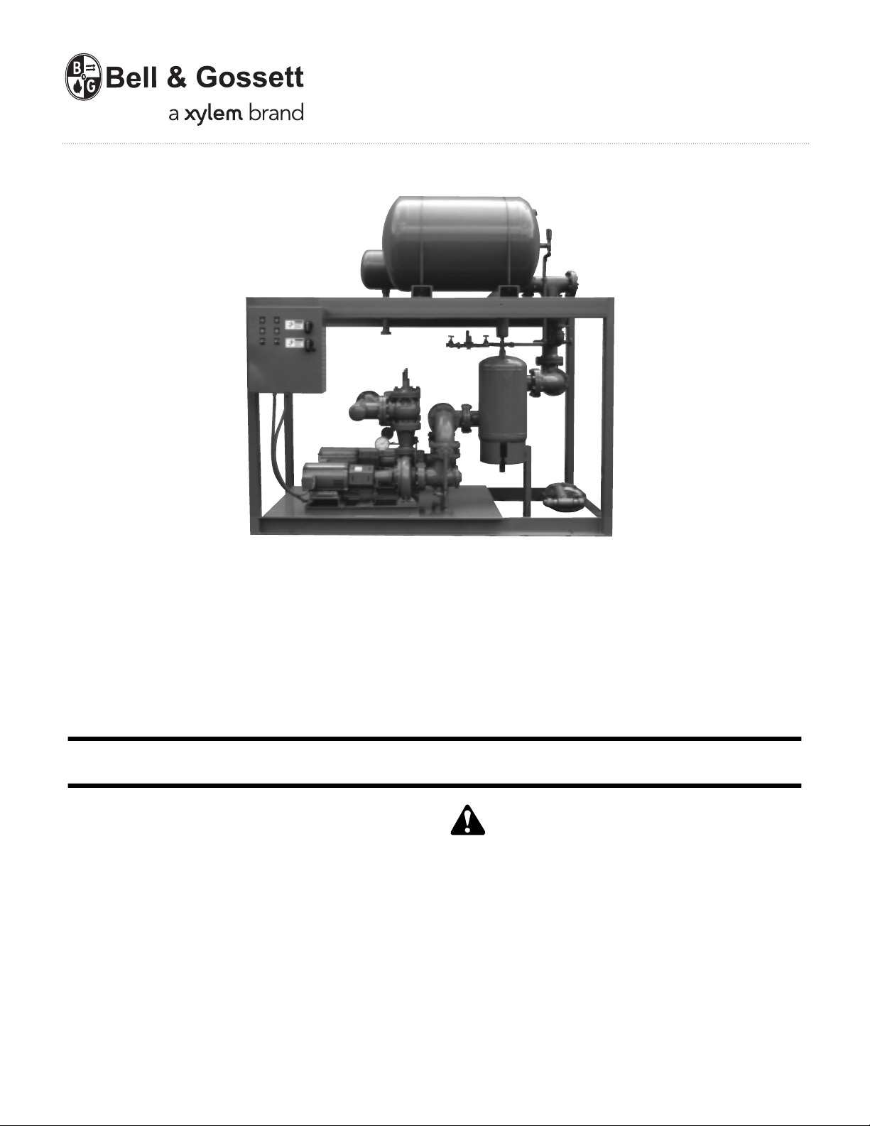
Heat Transfer Package
with Air Separation
INSTALLER: PLEASE LEAVE THIS MANUAL FOR THE OWNER’S USE.
DESCRIPTION
Frame mounted heat transfer package consisting of but not
limited to: heat exchanger, air separation apparatus, pump(s),
motor(s), triple duty check valve(s), relief valve(s), pressure
reducing valve, gauge(s), thermometer, and interconnecting
piping. The following options are also available: motor starter(s),
condensate trap, and steam valve.
OPERATIONAL LIMITS
The standard design pressure is 125 PSI unless otherwise indicated. The ASME nameplates will indicate the ratings of the
pressure vessels and relief valves. If a control panel is supplied
refer to the nameplate for operating voltage and full load AMP
current draw.
This safety alert symbol will be used in this manual and on
the Heat Transfer Package Safety Instruction decal to draw
attention to safety related instructions. When used, the safety
alert symbol means ATTENTION! BECOME ALERT! YOUR
SAFETY IS INVOLVED! FAILURE TO FOLLOW THESE
INSTRUCTIONS MAY RESULT IN A SAFETY HAZARD.
SAFETY
INSTRUCTIONS
Page 2

2
Heat Transfer Package
INSTRUCTIONS
UNIT IDENTIFICATION
The unit nameplate give identification and rating information as identified in Figure 1.
Units with electrical panels also are identified with a nameplate as shown in Figure 2.
Permanent records for this unit are kept by the factory number and it must therefore be
used with all correspondence and spare parts orders.
Model No.
Factory No.
Wired for Volts Hz Ph
System FL Amps
Largest Motor HP
System Flow GPM
Suction Pressure PSIG
Discharge Pressure PSIG
Pump TDH Feet
Date Code
FIGURE 2
FIGURE 1
BELL & GOSSETT
PACKAGED
PRODUCTS
MODEL NUMBER
FACTORY NUMBER
SHIPPING ORDER DATE
PUMP
HEAT EXCHANGER
Page 3

3
TABLE OF CONTENTS
HEAT TRANSFER PACKAGE
Page
SECTION 1
General Description . . . . . . . . . . . . . . . . . . . . . . . . . . . . . . . . . . . . . . . . . . . . . . . . . . . 4
Purpose of Manual . . . . . . . . . . . . . . . . . . . . . . . . . . . . . . . . . . . . . . . . . . . . . . . . . . . . 4
Safety Instruction . . . . . . . . . . . . . . . . . . . . . . . . . . . . . . . . . . . . . . . . . . . . . . . . . . . . . 4
Storage & Handling . . . . . . . . . . . . . . . . . . . . . . . . . . . . . . . . . . . . . . . . . . . . . . . . . . . 4
Electrical Connections . . . . . . . . . . . . . . . . . . . . . . . . . . . . . . . . . . . . . . . . . . . . . . . . . 4
Piping Connections . . . . . . . . . . . . . . . . . . . . . . . . . . . . . . . . . . . . . . . . . . . . . . . . . . . 5
SECTION 2
Installation . . . . . . . . . . . . . . . . . . . . . . . . . . . . . . . . . . . . . . . . . . . . . . . . . . . . . . . . . . 5
SECTION 3
Putting the Unit into Service . . . . . . . . . . . . . . . . . . . . . . . . . . . . . . . . . . . . . . . . . . . . 6
Troubleshooting – Electrical . . . . . . . . . . . . . . . . . . . . . . . . . . . . . . . . . . . . . . . . . . . . . 7
Factory Service . . . . . . . . . . . . . . . . . . . . . . . . . . . . . . . . . . . . . . . . . . . . . . . . . . . . . . 7
Maintenance . . . . . . . . . . . . . . . . . . . . . . . . . . . . . . . . . . . . . . . . . . . . . . . . . . . . . . . . . 7
APPENDIX
Start Up Check List – Piping . . . . . . . . . . . . . . . . . . . . . . . . . . . . . . . . . . . . . . . . . . . . 8
Start Up Check List – Electrical . . . . . . . . . . . . . . . . . . . . . . . . . . . . . . . . . . . . . . . . . . 8
NOTE:
The information contained in this manual is intended to assist operating personnel by providing information on the characteristics of the purchased equipment.
It does not relieve the user of the responsibility to adhere to local codes and ordinances
and the use of accepted practices in the installation, operation and maintenance of this
equipment.
Further information pertaining to the installation, operation, and maintenance of your Heat
Transfer Package can be found in the I.O.M.s for the associated equipment provided. See
section 1.26 for a list of manual part numbers.
Page 4

4
1.1 DESCRIPTION
1.2 The Bell & Gossett Heat Transfer Package is a complete heating system providing pumping, air separation, flow control and (as an option) temperature
regulation. In addition, it is furnished with a suction/
discharge pressure gauge, ASME safety relief valve,
pressure regulating system fill valve and pump servicing shut-off valves to minimize installation time and
errors.
1.3
PURPOSE OF MANUAL
1.4 This manual is furnished to acquaint you with some of
the practical ways to install, operate, and maintain this
unit. Read it completely before doing any work on
your unit and keep it handy for future reference.
1.5 Equipment cannot operate well without proper care.
To keep this unit at top efficiency, follow the recommended installation and servicing procedures outlined
in this manual.
1.6 SAFETY INSTRUCTION
1.7 This safety alert symbol will be used in this manual to
draw attention to safety related instructions. When
used the safety alert symbol means ATTENTION
BECOME ALERT! YOUR SAFETY IS INVOLVED!
FAILURE TO FOLLOW THIS INSTRUCTION MAY
RESULT IN A SAFETY HAZARD.
1.8
ADDITIONAL SAFETY REQUIREMENTS
1.9 Even when the motor is stopped, it should be considered “alive” as long as its controller is energized.
Keep hands away from the output shaft until the
motor has completely stopped, and the input power is
removed from the motor control panel.
1.10 Always use accurate test meters when checking electrical components. Always work with another person
in case of an emergency.
1.11
STORAGE & HANDLING
1.12 When the Heat Transfer Package is received, make a
visual inspection of the unit, checking for any damages that may have occurred in shipment. The unit
should also be checked against the shipping list to
account for the un-mounted components which are
boxed and bound to the unit.
1.13 If any damages are found or parts missing, note this
on the delivery receipt and inform your B&G Factory
Representative at once. Care should be taken to prevent damage due to dropping or jolting when moving
the unit. Transportation damage should be brought to
the carrier’s attention immediately upon receipt.
1.14 For long periods of storage, the unit should be
covered to prevent corrosion and contamination from
dirt. It should be STORED in a clean, dry location
between 0 – 170°F. The relative humidity should not
exceed 85%. The unit should be checked periodically
to ensure that no condensation has formed. After
storage, again check that it is dry before applying
power.
1.15 The unit is mounted on wooden skids which provide
for safe and easy movement to the installation site.
1.16 The final location should allow ample space for servicing all components of the unit. Be sure to allow
room for removal of the heat exchanger tube bundle,
should it be necessary.
1.17 The wooden skids should be removed and the base of
the frame leveled, grouted and bolted to the floor or
pad.
1.18
ELECTRICAL CONNECTIONS
1,19 The input voltage tolerance is +10/-10%.
1.20 All electronic equipment is susceptible to failure if
operated in ambient temperatures outside of its rating. The OPERATING temperature range for this unit
is 32 – 105°F. The relative humidity should not exceed
95% noncondensing. The unit should not be operated
outside these extremes.
1.21
GROUND CONNECTION
1.22 A grounding terminal is provided for a dedicated
ground wire connection. All provisions of the National
Electrical Code and local codes must be followed.
1.23
POWER WIRING
1.24 Power wire types and sizes must be selected based
upon conformance with the National Electrical Code
and all local codes and restrictions. In addition, only
copper (Cu) wire related for at least 75°C may be used
for the power connections. Refer to the input current
as listed on the motor nameplate when sizing wire.
WARNING: Prevent electrical shocks. Disconnect
the power supply before beginning installation.
Failure to follow these instructions could result in serious personal injury, death, and/or property damage.
WARNING: Electrical shock hazard. Inspect all
electrical connections prior to powering the unit.
Wiring connections must be made by a qualified electrician in accordance with all applicable codes, ordinances,
and good practices.
Failure to follow these instructions
could result in serious personal injury, death, and/or
property damage.
WARNING: Conduit grounds are not adequate. A
separate ground wire must be attached to the
ground lug provided in the enclosure to avoid potential
safety hazards.
Failure to follow these instructions could
result in serious personal injury, death, and/or property
damage.
CAUTION: Burn hazard. Surfaces are hot when the
unit is in operation. Do not touch the piping, pumps,
heat exchanger, and tanks until the equipment has been
given enough time to cool down.
Failure to follow these
instructions could result in property damage and/or
moderate personal injury.
Page 5

1.25 FIELD CONNECTION DIAGRAMS
1.26 Refer to the specific Installation, Operation, and
Maintenance Manuals for specific details unique to
each component. See the list below.
Component IOM Part
(1) 1510 Pump P81673
(2) Triple Duty Valve 2"–10" V50960
(3) Triple Duty Valve 1"–1-1/2" V50899
(4) ASME Safety Relief Valve V55692
(5) Pressure Reducing Valve V55999
(6) Air Separator, Airtrol Fitting,
ASME Compression Tank S10300
(7) Enhanced Air Separator Model EAS A03852
(8) Vacuum Breaker None
(9) High Capacity Air Valve #107A A82003
(10) ASME Diaphragm
Pressurized Expansion Tanks A01500
(11) Drain-O-Tank Air Charger V56916
(12) Air Valve #87 None
(13) Heat Exchanger HT-50A-SM
(14) Suction Diffuser A91310
1.27 The following field connection diagrams should be
reviewed prior to unit installation and operation.
Drawing # Description
Job Specific Print Wiring
Job Specific Print Dimensional Drawings
1.28
PIPING CONNECTIONS
1.29 A 3/4" NPT system fill connection is located in the
piping to the expansion tank. It is provided with a gate
valve and a pressure reducing valve with built-in
anti-syphon check valve. The reducing valve is set for
12 PSI system pressure. The PRV may be adjusted to
a higher setting when installed in taller buildings.
1.30 Local codes may govern this connection when made
to a domestic cold water line.
1.31 IMPORTANT: Do not install and operate Bell &
Gossett Pumps, 3D Valves, Suction Diffusers, etc., in
closed systems unless the system is constructed with
properly sized safety devices and control devices.
Such devices include the use of properly sized and
located pressure relief valves, compression tanks,
pressure controls, temperature controls and flow controls as appropriate. If the system does not include
these devices, consult the responsible engineer or
architect before making pumps operational.
2.0
INSTALLATION INSTRUCTIONS
2.1 Location
2.2 Locate the pumping unit for ease of inspection, maintenance and service.
2.3
Leveling
2.4 Place the unit on its concrete foundation, supporting
it with steel wedges or shims.
2.5
Grouting
2.6 After the frame has been leveled and securely bolted
to the floor, a good grade of grout should be installed
beneath the base. A suggested mixture for grout is
one part Portland Cement and two or three parts
plain, sharp sand mixed with water until it will pour
easily. Commercial grout mixtures with suspended
iron particles are available. Wet the concrete base
before pouring grout. To hold wedges or shims in
place, allow the grout to flow around them and
beneath the entire length of the base flange.
2.7
Piping
2.8 Be sure to eliminate any pipe strain on the unit.
Support the pipes independently by use of pipe
hangers near the unit. Line up the vertical and horizontal piping so that the bolt holes of the flanges
match. DO NOT ATTEMPT TO SPRING THE PIPE
LINES INTO POSITION. The code for Pressure Piping
(A.S.A.B. 31.1) lists many types of supports available
for various applications.
2.9 As a rule, ordinary wire or band hangers are not adequate to maintain alignment. It is very important to
provide a strong, rigid support for the suction line. A
saddle hanger is recommended.
2.9.1 For critical installations, equipment for absorbing
expansion and vibration should be installed in the inlet
and outlet connections of the unit.
2.9.2 Inspect all piping connections. Joints may become
loose during transit due to vibration and shock. All
joints are to be checked for tightness. Flanged joints
should be checked for proper torque of all flange bolts
prior to filling the system with fluid.
2.9.3
Hot Water Supply Connection
2.10 The supply main may be connected directly to the
B&G Triple Duty Valve mounted on the pump discharge nozzle. In some installations, a flexible connector near the Triple Duty valve may be desirable.
2.11 Hot Water Return Connection
2.12 The return connection is made to the top opening of
the 2 pass heat exchanger head. The return piping
should approach the head such that a union or
flanged joint can be placed in the section of the piping which is at a right angle to the length of the heat
exchanger. This will allow easy removal of the head
the tube bundle without pipe interference.
2.13 Install a thermometer in the return line near the heat
exchanger.
2.14 Both supply and return mains should be piped so as
to prevent air trapping. All high points in the piping
system should be provided with manual vents to
remove excess air during initial fill. Automatic air vents
must not be used in locations where the system pressure may fall below atmospheric while pumping.
5
WARNING: The heating of water and other fluids
causes volumetric expansion. The associated
forces may cause failure of system components and
release of high temperature fluids. This will be prevented
by installing properly sized and located pressure relief
valves and compression tanks.
Failure to follow these
instruction could result in serious personal injury, death,
and/or property damage.
WARNING: Heavy load may drop if not lifted
properly. Do not lift the entire unit by the motor eye-
bolts. Lift the unit with slings placed under unit base rails.
Failure to follow these instructions could result in serious personal injury, death, and/or property damage.
CAUTION: Failure to check all joints for tightness
and flange bots for proper torque could result in
leaks and/or flooding.
Failure to follow these instructions
could result in property damage and/or moderate personal injury.
Page 6

6
2.15 Steam Supply and Piping
2.16 Care must be taken when installing the steam supply
piping to insure no condensate will flow to the pressure reducing (control) valve. Condensate impingement on the heat exchanger tubes will lead to permanent failure.
2.17
Condensate Piping
2.18 Review the condensate trap Installation, Operation, &
Maintenance manual prior to connecting the trap to
the heat exchanger. Install all recommended valves
and fittings to allow servicing the trap while the unit is
in operation. Install a strainer upstream of the trap to
protect the unit from material that may prevent it from
operating properly. Install a blowdown valve on the
strainer and periodically purge the strainer of debris.
2.19 Do not connect condensate line from trap to condensate main that is above the heat exchanger without
making special provisions to keep the heat exchanger
totally free of condensate.
2.20 If traps are installed in parallel, the following should be
done. Service valves should be installed before and
after each trap so that each trap can be serviced while
the other trap remains in service. Unions should be
installed before and after each trap, between the trap
and service valves. These allow the trap to be
replaced without shutting down the system.
2.21
Drains
2.22 There is a drain plug in the pump volute.
2.23 There is a drain on the bottom of the air separator.
This port could be used as the primary drain for the
return piping since it is the low point of the system.
2.24 The supply main cannot be drained through the air
separator above because the Triple Duty valve acts as
a check valve. The lower port on the back of the Triple
Duty valve may be used as a drain for this section of
the piping. If this is undesirable, a separate drain point
must be provided in the supply piping.
2.25 Since the relief valve is located relatively high above
the floor, it is recommended that the outlet side of the
valve be piped to an open drain per local codes. The
pipe size must not be less than the outlet size and the
drain piping must run so as to avoid water trapping.
The end of the drain pipe must not be threaded to
avoid installation of a valve or plug.
2.26 The expansion tank drain is provided with a hose bibb
valve, therefore a garden hose can be used conveniently for draining.
2.27 Wiring
2.28 Check power leads in accordance with wiring diagram enclosed in control cabinet, if this option was
supplied. If a control panel was not supplied, make
wiring connection per the motor manufacturer’s
recommendations.
2.29
Lubrication
2.30 Before starting, all pumps and motors should be
checked for proper lubrication.
3.0
PUTTING THE UNIT INTO SERVICE
3.1 The following procedure is suggested for the initial
start-up.
3.2 Fill the system with water.
3.3 With the fill valve left open, vent all of the high points
in the piping system to remove the trapped air.
3.4 On units with ASME compression tanks, open the
vent valve located on the Airtrol Tank Fitting. Bleed
the air from the tank until water emits from the valve.
Close the valve.
3.5 Align pump coupling (see pump instruction sheet).
Check Bearing Lubrication.
3.6 Check pump rotation, 3 Phase motors only.
WARNING: Electrical shock hazard. Inspect all
electrical connections prior to powering the unit.
Wiring connections must be made by a qualified electrician in accordance with all applicable codes, ordinances,
and good practices.
Failure to follow these instructions
could result in serious personal injury, death, and/or
property damage.
DANGER: Explosible. Do not operate the heat
exchanger outside the limits defined on the heat
exchanger nameplate.
Failure to follow these instructions will result in serious personal injury, death,
and/or property damage.
CAUTION: Burn hazard. The system may contain
steam or hot water under pressure. Close the valves
to isolate the system. Drain and vent the system and allow
surfaces to reach acceptable temperatures prior to servicing.
Failure to follow these instructions could result in property damage and/or moderate personal
injury.
WARNING: Conduit grounds are not adequate.
A separate ground wire must be attached to ground
lug provided in the enclosure to avoid potential safety
hazards.
Failure to follow these instructions could result in serious personal injury, death, and/or property
damage.
CAUTION: Seal damage may occur. Do not run
pumps dry. Fill and vent the pump volute prior to
operation.
Failure to follow these instructions could result in property damage and/or moderate personal
injury.
WARNING: Rotating shaft can catch loose clothing.
Do not operate the pump without all guards in place.
Failure to follow these instructions could result in
serious personal injury, death, and/or property damage.
Page 7

7
3.7 With the disconnect switch engaged to the “ON” position, turn selector switch to the “HAND” position
momentarily, then “OFF.” Observe the pump shaft
rotation.
3.8 If incorrect, turn the main disconnect off and interchange any two wire leads leaving the starter overload
block and going to the motor.
3.9 Run the pump. Take an ampere reading on the pump
motor. If it is greater than the rated nameplate full load
current,
close the Triple Duty valve (turn stem clock-
wise) until the motor current decreases to the nameplate value.
3.10 Note the value indicated by the pointer on the calibrated scale of the Triple Duty valve stem. Tag the
valve with this reading for future reference. The stem
is to be returned to the position at all times when the
pump is in operation, otherwise, motor overloading
may result.
3.11
TROUBLESHOOTING – ELECTRICAL
3.12 Starter overload relays must be manually reset when
tripped. To reset the overload relay press the external
reset button.
3.13 Pinpointing failures in the control circuitry largely
depends on the understanding of the circuit line diagram furnished with each unit and the proper use of
test instruments. Some of the recommended test
instruments are:
a) Combination Volt-Ohm-Ammeter (VOM multi-
tester) with a 600 volt AC scale (or greater).
b) Clamp-on Ammeter (Amprobe or equal) with
ampere capacity up to 100 amps.
c) Fuse puller.
3.14 Use of “Test Light” for continuity tests is not recommended since these devices do not indicate the
actual voltage present at the test point. Locating
trouble spots with the use of “Jumper Wire” is strongly
discouraged.
3.15
Failure and Probable Causes
3.16 Motor overload relay trips.
3.17 Probable causes:
(1) High ambient temperature around panel box.
(2) Actual line voltage above or below motor name-
plate voltage limits.
(3) Overload heaters improperly selected or installed
(loose hold screw).
(4) Unbalanced voltage between phases.
(5) Faulty motor.
(6) Pump loading beyond design conditions.
3.18
Factory Service
3.19 When requesting information from the factory, it is
imperative that the following data be available for
reference.
(a) Factory Number
(b) Model Number
(c) The
actual line voltage, current draw, suction, dis-
charge and system pressure, or other pertinent
information relative to the nature of the problem.
3.20
Maintenance
3.21 Lubricate motor and pump twice a year.
3.22 Repair any leaks in the hot water system immediately.
Prolonged entry of makeup water will seriously corrode the piping and foul the heat exchanger.
3.23 Clean out all strainers periodically.
3.24 Be aware of ‘gurgling’ sounds through the piping sys-
tem and the pump. It may indicate an air bound
expansion tank. Bleed air from tank.
3.25 When ordering replacement parts or inquiring about
the unit, always give the
complete data on the unit
nameplate as well as the component nameplate data.
DANGER: Troubleshooting live control panels
exposes personnel to hazardous voltages. Electrical
troubleshooting must only be done by a qualified electrician.
Failure to follow these instructions will result in
serious personal injury, death, and/or property damage.
DANGER: Troubleshooting live control panels
exposes personnel to hazardous voltages. Electrical
troubleshooting must only be done by a qualified electrician.
Failure to follow these instructions could result
in serious personal injury, death, and/or property
damage.
CAUTION: Prevent subsequent damage. A unit
showing symptoms of possible problems (noise,
leaks, vibration, and/or continual operation) must be corrected immediately.
Failure to follow these instructions
could result in property damage and/or moderate personal injury.
DANGER: High voltage 3 phase power can kill.
Disconnect and lockout power prior to servicing
unit.
Failure to follow these instructions will result in
serious personal injury, death, and/or property damage.
DANGER: Troubleshooting live control panels
exposes personnel to hazardous voltages. Electrical
troubleshooting must only be done by a qualified electrician.
Failure to follow these instructions will result in
serious personal injury, death, and/or property damage.
CAUTION: Burn hazard. The system may contain
steam or hot water under pressure. Close the valves
to isolate the system. Drain and vent the system and allow
surfaces to reach acceptable temperatures prior to servicing.
Failure to follow these instructions could result in property damage and/or moderate personal
injury.
Page 8

FINAL CHECK LIST
FINAL CHECK LIST
A. SYSTEM PIPING AND UNIT INSTALLATION
_____ 1. Is the unit base properly leveled, grouted and
secured?
_____ 2. Are all lubrication points properly lubricated?
_____ 3. Are the shut-off valves to the pump gauge(s)
open?
_____ 4. Is the shut-off valve to the pump suction open?
_____ 5. Is the Triple Duty valve on the discharge line open?
_____ 6. Is the piping properly supported so as to prevent
strains on the unit?
_____ 7. Is the system, including the pump, purged of
debris and air?
CAUTION: Seal damage may occur. Do not run
pumps dry. Fill and vent the pump volute prior to
operation. Failure to follow these instructions could re-
sult in property damage and/or moderate personal
injury.
_____ 8. Are the pump and motor shafts properly aligned?
_____ 9. Is the pump rotation correct?
_____10. Have all piping connections been made? Have all
flanged joints been checked for tightness?
B. ELECTRICAL WIRING AND CONTROL SETTINGS
_____ 1. Does the feeder line voltage correspond to the
unit voltage? Check the unit nameplate or motor
terminal connection.
WARNING: Electrical shock hazard. Inspect all
electrical connections prior to powering the unit.
Wiring connections must be made by a qualified electrician in accordance with all applicable codes, ordinances,
and good practices. Failure to follow these instructions
could result in serious personal injury, death, and/or
property damage.
_____ 2. Are the feeder wires correctly sized for the load?
_____ 3. Are the fuses in the disconnect switch correctly
sized? They must not exceed 1.75 times the full
load current of the motor. Usual sizing is 1.15 to
1.5 times the full load current.
_____ 4. Is the unit properly grounded?
WARNING: Conduit grounds are not adequate. A
separate ground wire must be attached to the
ground lug provided in the enclosure to avoid potential
safety hazards. Failure to follow these instructions could
result in serious personal injury, death, and/or property
damage.
_____ 5. Have all the power terminals in the control panel
been checked for tightness? This is imperative
since stranded wires tend to “flow” and become
loose after initial installation.
DANGER: High voltage 3 phase power can kill.
Disconnect and lockout power prior to servicing
unit. Failure to follow these instructions will result in
serious personal injury, death, and/or property damage.
Xylem Inc.
10661 Newkirk Street
Dallas, TX 75220
Phone: (469) 221-1200
Fax: (214) 357-5861
www.xyleminc.com/brands/bellgossett
Bell & Gossett is a trademark of Xylem Inc. or one of its subsidiaries.
© 2012 Xylem Inc. S11574C August 2012
 Loading...