

Page 1
INSTALLER: PLEASE LEAVE THIS MANUAL FOR THE OWNER’S USE.
SAFETY
INSTRUCTIONS
This safety alert symbol will be used in this manual and on the pump
safety instructions decal to draw attention to safety related instructions. When used, the safety alert symbol means ATTENTION!
BECOME ALERT! YOUR SAFETY IS INVOLVED! FAILURE TO FOLLOW THE INSTRUCTIONS MAY RESULT IN A SAFETY HAZARD.
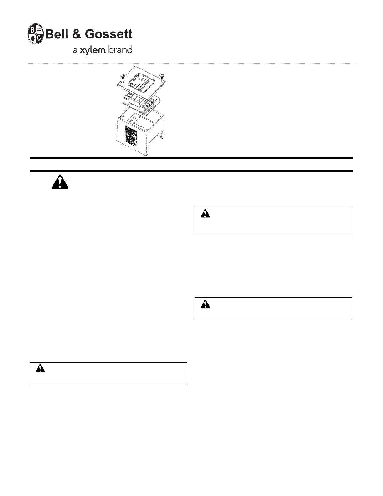
DESCRIPTION
The AZ-1A pump controller is field mounted to any NRF, NBF, SSF or
1
/12-1/6 HP Series PLTMbooster pump. The AZ-1A controller operates
the pump when the thermostat calls for heat. The controller can be
wired to fire the boiler through a 24-volt rated isolated endswitch. The
AZ-1A pump controllers are UL and cUL listed. When the AZ-1A is
mounted on a B&G pump, the pump/controller assembly maintains
the UL listings.
OPERATIONAL LIMITS
For use on B&G models NRF, NBF, SSF, and 1/12-1/6 HP Series PL
only. Do not use with pump that has larger than 1/6 HP motor.
Power Supply: 115-120 VAC, 60HZ, 1Ø
Maximum switch current: 5 Amps
OPERATION
The circulators wired to the AZ-1A are controlled by a low voltage
controller having an SPST switch (typically a thermostat). When there
is a call for heat, the relay is engaged to start the circulator, the amber
LED illuminates and the XX isolated end switch closes. This end
switch can be used to energize the boiler or other related controls.
When the thermostat is satisfied, the circulator and LED are turned off
and the end switch is opened.
AZ-1A INSTALLATION
1. Disconnect the electrical supply to the pump before installing the
AZ-1A controller.
WARNING: Electrical Shock Hazard
Disconnect and lock out the power before making electrical
connections. Failure to follow these instructions could result in
serious personal injury or death.
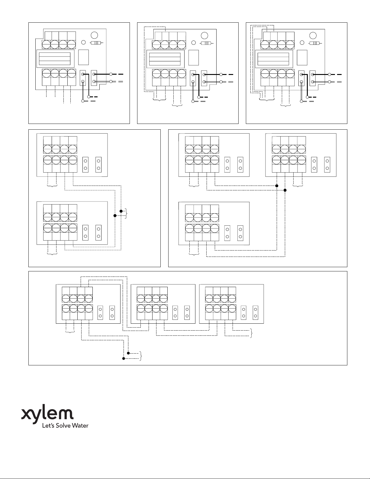
2. Refer to applicable wiring diagram
– Figure 1: 2 wire thermostat
– Figure 2: 3 wire thermostat
– Figure 3: 4 wire thermostat
– Figure 4: Multiple zones
– Figure 5: Multiple zones with boiler pump
– Figure 6: Multiple pumps with one thermostat
Consult local representative for other configurations.
3. Remove the screw that holds the steel conduit box cover to the
pump.
4. Remove the conduit box cover. The AZ-1A assembly replaces the
conduit box cover.
5. If AZ-1A is being installed onto an already installed pump, disconnect the black and white motor leads from the power supply.
6. Position the plastic base for the AZ-1A onto the steel conduit box
with the warning/caution label to the rear of the pump.
7. Verify that the electrical rating of the AZ-1A matches the values
shown on the nameplate of the circulator.
INSTRUCTION MANUAL
P86315B
TM
ZoneTrol II
Model AZ-1A
8. Make the electrical connections according to the wiring diagram
provided. Run the pump power wiring through one of the holes in
the metal conduit box. Do not attach conduit to the hole in the
plastic base. This hole is only for 24 volt control wiring. Use 14
AWG copper electrical wire with a minimum temperature rating of
90°C. Refer to your electrical code for wiring restrictions.
WARNING: Electrical Shock Hazard
Electrical connections are to be made by a qualified electrician in accordance with all applicable codes, ordinances and
good practices. Failure to follow these instructions could result in
serious personal injury, death and/or property damage.
9. Run the thermostat wires through the grommet in the plastic base
and connect to the appropriate TR/TW terminals. Run the 24-volt
boiler control wires through the grommet in the plastic base and
connect to the XX terminals (See Fig. 3). Do not use the holes in
the metal conduit box for 24 volt control wiring. The holes in the
metal conduit box are for power wiring only.
10. Position the AZ-1A relay PC board in the plastic base with the
TM
electronic components on the top. Make sure that all pump
wiring connections are inside the box below the PC board.
Note that the hole in the PC board must line up with the mounting
hole in the plastic base.
WARNING: Electrical Shock Hazard
Improper assembly could cause electrical shock and fire.
Failure to follow these instructions could result in serious personal
injury, death and/or property damage.
11. Secure the AZ-1A PC board and plastic base to the conduit box
with one of the provided 8-32 screws.
12. Fasten the cover to the base using two of the provided 8-32
screws.
Multiple Zones (Figure 4)
When using multiple AZ-1A controls on a system with a boiler pump, each
controller should be connected to input power and its respective pump
as shown in Figures 1, 2, or 3, depending on style of thermostat(s).
Connect each thermostat to its respective AZ-1A. Wire the XX terminals on each AZ-1A to the TT Controls on the Boiler.
Multiple Zones with Boiler Pump (Figure 5)
When using multiple AZ-1A controls on a system with a boiler pump, each
controller should be connected to input power and its respective pump
as shown in Figures 1, 2, or 3, depending on style of thermostat(s).
Connect each thermostat to its respective AZ-1A. Wire the XX terminals to each zone AZ-1A to the T/R and T/W terminals on the Boiler
Pump AZ-1A. The XX terminals on the Boiler Pump AZ-1A are wired
to the TT Controls on the Boiler.
Multiple Pumps with One Thermostat (Figure 6)
When using AZ-1A controls on a system with multiple pumps and one
thermostat, each controller should be connected to input power and
its respective pump as shown in Figures 1, 2, or 3, depending on style
of thermostat.
Connect the thermostat to the first AZ-1A. Wire the AX AX terminals
of the first zone to the T/R and T/W terminals of the second AZ-1A.
Wire the XX terminals to the boiler TT control. Any number of additional pumps can be switched on by the same thermostat by
connecting the XX terminals to the T/R and T/W terminals of the next
AZ-1A.
Page 2
TB1
P/C AX AXP
PUMP ON
TB1
P/C AX AXP
PUMP ON
TB1
P/C AX AXP
PUMP ON
LINE PUMP
TB2
XXT/WT/R
}
THERMOSTAT
Figure 1: Two Wire Thermostat
TB1
TB2
THERMOSTAT
TB1
TB2
}
TT BOILER CONTROLS
P/C AX AXP
ZONE 1
P/C AX AXP
XXT/WT/R
XXT/WT/R
Zone 1
Pump
Controller
LINE PUMP
Zone 2
Pump
Controller
LINE PUMP
INPUT
POWER
Figure 4:
Multiple Zones
PUMP
TT BOILER
CONTROLS
LINE PUMP
TB2
THERMOSTAT
TT BOILER CONTROLS
XXT/WT/R
INPUT
POWER
Figure 2: Three Wire Thermostat
P/C AX AXP
TB1
TB2
THERMOSTAT
TB1
TB2
ZONE 1
P/C AX AXP
XXT/WT/R
XXT/WT/R
PUMP
Zone 1
Pump
Controller
LINE PUMP
Zone 2
Pump
Controller
LINE PUMP
LINE PUMP
TB2
THERMOSTAT
TT BOILER CONTROLS
XXT/WT/R
INPUT
POWER
Figure 3: Four Wire Thermostat
TB1
TB2
P/C AX AXP
TT BOILER
CONTROLS
XXT/WT/R
Boiler
Pump
Controller
LINE PUMP
Figure 5:
Multiple Zones with
Boiler Pump
PUMP
ZONE 2
THERMOSTAT
TB1
TB2
P/C AX AXP
THERMOSTAT
XXT/WT/R
ZONE 2
THERMOSTAT
Zone 1
Pump
Controller
LINE PUMP
Xylem Inc.
P/C AX AXP
TB1
TB2
TT BOILER
CONTROLS
XXT/WT/R
Zone 2
Pump
Controller
LINE PUMP
8200 N. Austin Avenue
Morton Grove, Illinois 60053
Phone: (847) 966-3700
Fax: (847) 965-8379
www.xyleminc.com/brands/bellgossett
Bell & Gossett is a trademark of Xylem Inc. or one of its subsidiaries.
© 2012 Xylem Inc. P86315B May 2012
P/C AX AXP
TB1
TB2
XXT/WT/R
Zone 3
Pump
Controller
LINE PUMP
TO NEXT UNIT
T/R AND T/W
Figure 6: Multiple Pumps
with One Thermostat
 Loading...