

Page 1
INSTRUCTION MANUAL
P86272B
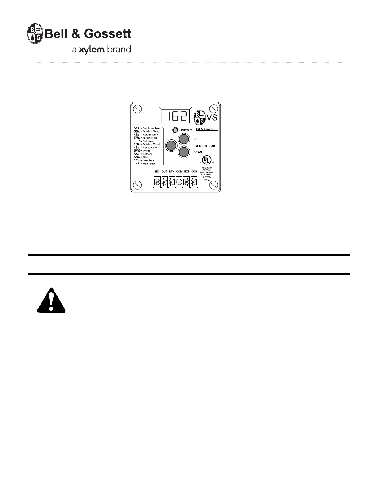
Model VS Variable Speed Pump Control
INSTALLER: PLEASE LEAVE THIS MANUAL FOR THE OWNER’S USE.
DESCRIPTION
The VS is a hydronic heating control. The temperature of the
SAFETY
INSTRUCTION
This safety alert symbol will be used in this manual to draw
attention to safety related instructions. When used, the safety
alert symbol means ATTENTION! BECOME ALERT! YOUR
SAFETY IS INVOLVED! FAILURE TO FOLLOW THESE
INSTRUCTIONS MAY RESULT IN A SAFETY HAZARD.
heating water is controlled by regulating the speed of a pump
which injects water from a hot boiler loop (Primary loop) into a
cooler heating loop (Secondary loop). As the speed of the
pump increases, more hot water is sent into the Secondary
loop, and the temperature of the heating water increases.
The VS can be used as an outdoor reset control. When the
outdoor temperature falls below an adjustable start point, the
heating system is activated. The temperature of the Secondary loop water is then automatically regulated based on
outdoor temperature. The outdoor reset function maintains
constant and comfortable ambient building temperature in all
weather conditions.
The VS can also be used as a set point control. In this mode of
operation, the VS will control the pump speed to hold a constant temperature (determined by the user) in the Secondary
loop. The outdoor start temperature can be set to ON so the
set point will be held regardless of outside temperature.
The VS is equipped with a Primary loop sensor. This sensor
monitors the temperature of the boiler return water. If the
boiler return water falls below an adjustable temperature, the
VS can be configured to slow down the speed of the injection
pump to help the boiler return water temperatures recover.
The VS can be enabled or disabled from a standard thermostat
or switch, or the VS can reduce the temperature of the heating
loop water when the building is not occupied or when
occupants are sleeping.
Page 2

REQUIREMENTS
ELECTRICAL SAFETY
WARNING: ELECTRICAL SHOCK HAZARD
Electrical connections are to be made by a qualified
electrician in accordance with all applicable codes, ordinances and good practices. Failure to follow these instructions could result in serious personal injury, death and/or
property damage.
VS
Outdoor
Sensor
Secondary Loop
Sensor
Boiler Return
Sensor
VS Pump
PRIMARY
LOOP
SECONDARY
LOOP
Boiler
Primary-Secondary Variable Speed Injection Mixing
Lower Temperature System
VS
Outdoor
Sensor
Secondary Loop
Sensor
Boiler Return
Sensor
VS Pump
PRIMARY
LOOP
SECONDARY
LOOP
Boiler
Primary-Secondary Variable Speed Injection Mixing
Multiple Temperature System
VS
Outdoor
Sensor
Secondary Loop
Sensor
Boiler Return
Sensor
PRIMARY
LOOP
SECONDARY
LOOP
Boiler
Primary-Secondary
Variable Load System
VS Pump
2
OPERATIONAL LIMITS
These controls are to be used with wet rotor pumps designed
to pump liquids compatible with their cast iron, bronze or
stainless steel body constructions.
Electrical Rating
VS Control: 115v, 60hz, 1Ø
Injection Pump: 115v, 60hz, 1Ø
Max. Rating 1/8 HP
Permanent Split Capacitor
Secondary Loop Pump: 115v, 60hz, 1Ø or 230v, 60hz, 1Ø
Max. Rating of 8 amps
TYPICAL APPLICATIONS (Fig. 1)
Page 3
DESIGN SELECTION
To select the correct pump, pipe size and balance valve:
1.Determine the Primary Loop Temperature. This is the
temperature the primary loop will maintain.
2. Determine the Secondary Loop Temperature. This is the
design temperature of the secondary loop. If an outdoor
reset function is being employed, this is the required
temperature of the secondary loop under maximum load.
3. Determine the design temperature drop (
T or delta T) of
the secondary loop. This is the design drop in temperature through the secondary loop. In most radiant
heat applications,
T is 10. Other types of radiation such
as baseboard have a higher design
T.
4. Determine the Maximum Injection Heat Load. This is the
maximum heat requirement of the secondary loop. The
maximum injection heat load is based on the injection
pump running at the highest speed. As the pump speed
is reduced, less heat will be delivered to the secondary
loop.
5. Use the equation below to determine the design injection
flow rate.
Design Injection Flow Rate (GPM) =
Maximum Injection Heat Load (BTU/hr)
500 (T
primary - Tsecondary + Tsecondary) (ºF)
6. Use the table below to select the appropriate pump, pipe
size and balance valve.
Design Injection Injection B&G Circuit Setter
®
B&G Circuit Setter
®
B&G
Flow Rate (GPM) Pipe Size Balance Valve Valve Setting Pump
1.5
1
/2" CB-1/2 / CB-1/2S 18 / 25 NRF-22
3.5
1
/2" CB-1/2 / CB-1/2S full open / 6 NRF-22
6
3
/4" CB-3/4 / CB-3/4S full open / 12 NRF-22
10 1" CB-1 / CB-1S full open / full open NRF-22
15 11/4" CB-11/4 / CB-11/4S 5 / 5 NRF-22
24 1
1
/2" CB-11/2 full open NRF-33
Example:
1. Primary Loop Temp: 140ºF
2. Secondary Loop Temp: 100ºF
3. Design temperature drop: 10ºF
4. Maximum injection heat load: 150,000 BTU/hr
5. Calculate Injection flow rate
Design Injection Flow Rate (GPM) =
150,000 (BTU/hr)
=
150,000
= 6 GPM
500 (140 - 100 + 10) (ºF) 25,000
6. Injection Pipe size is
3
/4", full open CB-3/4 balancing valve and NRF-22
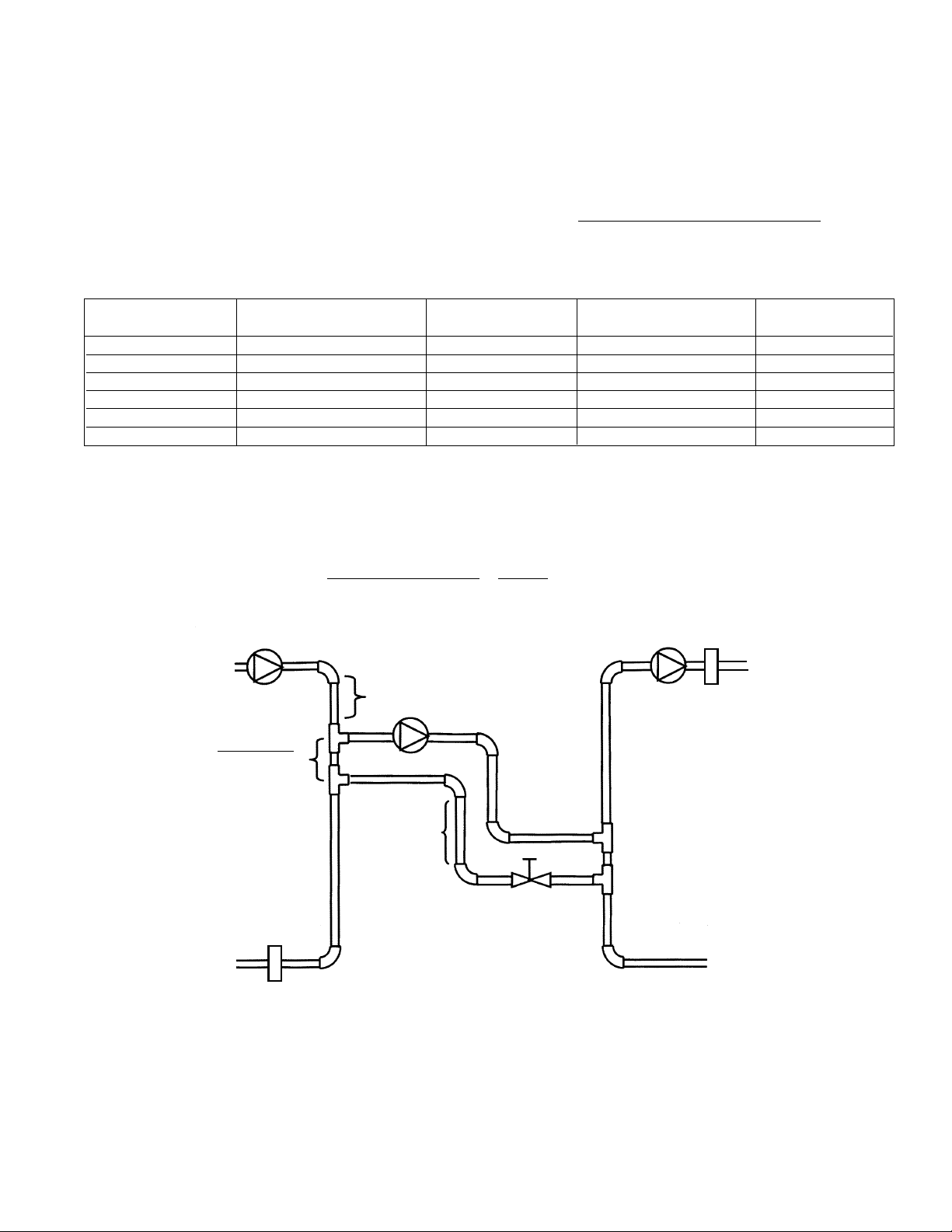
Minimum of 1' of
pipe drop required
to create a thermal
trap
Rule of Thumb
3 pipe diameters
between tees
Minimum of 8 pipe diameters upstream
and 4 pipe diameter downstream of straight
pipe on either side of tees to prevent any
possibility of “jet flow” through the
common piping.
Secondary
Loop
Secondary
Loop Pump
Primary
Loop Pump
Secondary
Loop Sensor
Boiler Return
Sensor
Primary
Loop
Injection Pump
Balance
Valve
3
FIG. 2
Based on (5) feet of pipe, (4) 90° elbows, (4) tees. Correct pipe and pump size calculation for any application should be performed by a qualified engineer or contractor.
Page 4
PIPING
PIPING OVERVIEW
• The Primary loop may have multiple injection loops or other
takeoffs. However, the piping for each injection system
must meet the requirements described below.
• The Injection piping can be installed in either a horizontal or
a vertical configuration.
• The pipe diameters of the Primary and Secondary loops
may differ.
• The Injection Piping diameter must be at least one pipe size
smaller than the smaller of the Primary and Secondary loop
piping. For example, if the Primary loop diameter is 1
1
/4"
and the Secondary loop diameter is 1", then the diameter of
the Injection piping must be
3
/4" or smaller.
• The Injection pump motor must be a fractional B&G NRF,
NBF or SSF permanent split capacitor type pump. (Refer to
operational limits on Page 2 for pump information.) The
Injection pump will control the amount of water pumped
from the Primary loop into the Secondary loop.
• A balancing valve should be installed on the injection return
piping. This helps to balance the system.
• The distance between the injection tees should be as short
as possible. The rule of thumb distance between the tees is
3 times the pipe diameter. For instance, if the pipe diameter
is 1" then the length of straight pipe between the two
injection tees should be 3".
HORIZONTAL PIPING CONFIGURATION
• The Injection piping can be installed horizontally as shown
in Fig. 2.
• The Injection supply piping should run horizontally from the
Primary to the Secondary loop.
• On the Injection piping it is necessary to install a heat trap
to prevent heat from the Primary loop entering the Secondary loop when the Injection pump is not running.
• The injection piping must drop down vertically at least 18"
and then rise back up vertically at least 18".
VERTICAL PIPING CONFIGURATION
• The Injection piping can be installed vertically.
• The Primary loop must be at least 18" vertically above the
Secondary loop.
4
CAUTION: The Injection pump and pipe sizing
should be performed by a qualified engineer or
contractor.
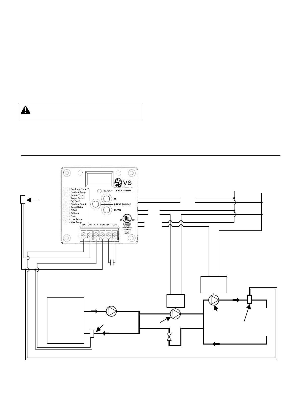
Secondary
Loop Sensor
Secondary
Loop Pump
Outdoor
Sensor
BLUE
RED
BLACK
120 VAC
LINE NEU
Setback or
Remote Enable
L
O
A
D
Pump
Starter /
Motor
••
Pump
Motor
•
Injection
Pump
Boiler Return
Sensor
Boiler
••
Injection pump must be connected directly to 120VAC motor N.O. pump starter.
••
Secondary pump starter/motor can be 115V or 230V.
VS WIRING DIAGRAM (Fig. 3)
NOTE: Injection Pump and the VS Control MUST be
wired to the same power circuit. The secondary loop
pump can be wired to a different circuit if required.
Page 5

5
CONTROL INSTALLATION
MOUNTING THE CONTROL
• The VS is designed to mount on a standard 4"x4" electrical
box.
• Locate the VS in a convenient location near the variable
speed pump. The VS can not be mounted more than 500'
from any sensor location.
• Mount the VS away from excessive heat or cold. Ambient
operating temperature is from 20° to 120°F.
• After completing all the wiring connections (see Figure 3)
use the two corner screws provided to mount the VS to the
electrical box.
INSTALLING THE SENSORS
• The sensor wires can be extended up to 500' from the
controller. If the sensor wires are located near strong
sources of electro-magnetic interference (EMI), shielded
cable or twisted pair should be used, or the wires can be
run in a grounded metal conduit. If using shielded cable, the
shield wire should be connected to the
COM terminal on the
control and not to earth ground. Do not run wires in conduit
with line voltage.
• The Outdoor sensor should be mounted in the shade on the
north side of the building (never in direct sunlight). Keep the
sensor approximately 10' above ground level and away
from doors, windows, exhaust fans, or other heat sources.
Do not insulate.
• In a primary/secondary application, the secondary loop
sensor should be mounted downstream of the inlet loop
and before any major heating units. That will provide the
control a more accurate reading (refer to Figures 1 and 2).
• If used, the boiler return water sensor should be mounted
downstream of all the return loop piping and before the
boiler on the primary loop. (Refer to Figures 1 and 2.)
• Strap the boiler return and secondary loop sensors to the
pipe as shown in Figure 4.
• Wrap the pipe and sensor assembly with insulating tape to
insure adequate heat transfer to the sensor.
WIRING THE SENSORS
• The sensor wires have no polarity. Either wire from a sensor
can be connected to the appropriately marked VS screw
terminal (see Figure 5) or the sensor common marked
COM.
• Either or both screw terminals marked
COM can be used as
the sensor common. They are interchangeable.
• If the sensor wires have been extended, connect the shield to
a
COM terminal. Do not connect the shield at the sensor end.
• The two wires from the Secondary loop sensor must be
connected to the VS front screws marked
SEC and COM.
• The two wires from the Outdoor sensor must be connected
to the VS front screws marked
OUT and COM.
• The two wires from the Boiler return water sensor, if used,
must be connected to the VS front screws marked
RTN and
COM. (If not using this sensor, see the NOTE in Low Return
pg. 11.)
WIRING THE VS POWER
• Attach 120VAC line voltage to the two Blue wires extending
from the back of the VS.
• Use wire nuts, or wrap the connections with electrical tape.
• Class 1 voltage must enter the 4" conduit box through a
different opening from any Class 2 wiring.
WIRING THE INJECTION PUMP
• The injection pump MUST be wired to the same power
circuit as the VS control.
• The Red wires provide a solid state switching output to the
Injection pump.
• The Injection pump motor must be a fractional horsepower
permanent split capacitor type motor.
• The Red wires must be directly in series with the pump
power (see Figure 3). The signal can not be wired through
any pilot duty relays or pump starters.
• If used, safety limit switches or HOA switches must be
wired in series with the pump power.
• Use wire nuts, or wrap the connections with electrical tape.
• Class 1 voltages must enter the electrical box through a
different opening from any Class 2 wiring.
WIRING THE SECONDARY LOOP PUMP
• The Black wires provide a Normally Open (N.O.) relay
output for the Secondary loop pump.
• The Black wires are a dry contact output only, They do not
source any power.
• Use wire nuts, or wrap the connections with electrical tape.
• Class 1 voltages must enter the electrical box through a
different opening from any Class 2 wiring.
• Wire the N.O. dry contacts to the pump starter.
WARNING: ELECTRICAL SHOCK HAZARD
Disconnect and lock out power before making electrical connections. Failure to follow these instructions could
result in serious personal injury, death and/or property
damage.
FIG. 4
WARNING: This Bell & Gossett control is strictly an
operating control; it should never be used as a primary limit or safety control. All equipment must have its
own certified limit and safety controls required by local
codes. The installer must verify proper operation and
correct any safety problems prior to the installation of this
Bell & Gossett control. Failure to follow these instructions
could result in serious personal injury, death and/or
property damage.
Page 6

6
WIRING THE EXT INPUT
• The EXT and COM terminals can only accept a dry contact
input.
• The control is factory supplied with a metal jumper between
the
EXT and COM terminals. If the control is not using a
Setback or Thermostat, the jumper must be left in place
and the control should be left in the default Thermostat
mode. If no wiring is connected to the
EXT and COM
terminals, the jumper must be in place for the control to
operate.
• The
EXT Input can be configured to provide one of the
following two functions:
Setback Mode
• The EXT Input can be used to accept an input from an
external clock with a normally open switching action to
lower the temperature of the Secondary loop when the
building is not occupied, or when the occupants are
sleeping. Remove the jumper between the
EXT to COM
terminals. Connect external clock to the EXT and COM
terminals.
• When the
EXT to COM terminals are open, the VS will run
normally.
• When the
EXT to COM terminals are shorted/closed the
temperature of the Secondary loop will be reduced by the
number of degrees of
Setback (see pg. 11).
Thermostat Mode
• The EXT Input can be used to accept an input from a
thermostat to activate the heating system. Remove the
jumper between the
EXT to COM terminals. Connect the
thermostat to the
EXT and COM terminals.
• When the
EXT to COM terminals are open, the VS will not
be active. Both pump outputs will be disabled.
• When the
EXT to COM terminals are shorted/closed the VS
will activate the heating system if there is a call for heat.
SETTING THE OPERATING MODES
• Whenever the VS is powered up, it will display the software
version number and then the current operating modes.
Each display will remain on the screen approximately 5
seconds. If the modes are correct, there is no need to make
any adjustments.
• Once the modes have been set for a particular application,
they will be retained in memory and will not need to be reset.
• Note that if you do change an operating mode, you will
need to reset all other settings.
• An operating mode can only be changed when it is being
displayed in the start-up sequence. To restart the sequence
it is necessary to remove power to the VS and then power it
again.
• To change a mode, hold down the center button while
pushing either the UP or DOWN button to toggle between
the settings. (Refer to Figure 5.)
• When the correct mode is selected, release the buttons and
wait approximately 5 seconds to go the next mode.
• Set the operating modes as described in sequence below:
°F or °C – Fahrenheit or Celsius Temperature Operation
• If the display shows °F then the VS will operate in
Fahrenheit degrees.
• If the display shows °
C then the VS will operate in Celsius
degrees.
r or S – Reset or Set Point Operation
• If the display shows r then the VS will run with as an
outdoor reset control (see pg. 10). As it gets colder outside,
the VS will automatically increase the temperature of the
Secondary loop.
• If the display shows S then the VS will hold the selected set
point temperature in the Secondary loop. To select the
Set
Point,
see chart on pg. 8).
Sb or tt – Setback or Thermostat Mode
• If the display shows Sb then the VS will use the EXT Input
for an external clock or switch to lower temperature of the
Secondary loop. In such a case, the VS will lower
secondary loop water temperature by the amount of the
Setback (
Sbc ) on a short/closure between EXT and the
COM terminals. When switched to an open status, the VS
will go into Boost mode (increase secondary loop
temperature by the Setback (
Sbc)) for one hour.
• If the display shows
tt then the VS will use the EXT Input for
a thermostat. When the thermostat input is open, both
pump outputs will be disabled.
no or YES – Pump Exercise every 3 idle days
• If the display shows YES then the VS will activate both the
Secondary Loop pump and the Injection pump for 10
seconds every 3 idle days.
• If the display shows
no then the VS will only run the pumps
when the system requires it. This setting will prevent hot
water from being pumped into the Secondary loop when
there is no call for heat.
nrS or rS – Return Sensor
• If the display shows nrS (No Return Sensor), then the VS
will not monitor the boiler return temperature.
• If the display shows
rS (Return Sensor), then the VS will
monitor the boiler return temperature. If the Return
Temperature falls below the Low Return Temperature
LOr,
the VS will reduce the injection pump to half the current
speed until the Return Temperature rises above the
Minimum Return again.
CAUTION: If power is applied across the COM and
EXT terminals, the VS may be damaged.
Page 7

7
INITIAL SETTINGS FOR A RESET CONTROL
(see r on pg. 6)
• After setting the operating mode, the VS will display the temperature of the Secondary loop. This is the default display.
• To see and/or adjust the other parameters, press then
release the center button marked
PRESS TO READ. The VS
will display a code to indicate which parameter will be
displayed next. After two seconds, the value of the
parameter will be shown.
• For those parameters where the values can be set (shown
on chart pg. 8), press the
UP or DOWN button to change
the value while it is being displayed. Holding the
UP or
DOWN button will cause the value to change more quickly.
• The
Outdoor Cutoff (COF ), also known as warm weather
shut down, temperature setting is the outdoor temperature
above which the VS will not give heat. The factory default
setting is 60°F.
• The Reset Ratio (rSt ) determines how quickly the water
temperature in the Secondary loop will increase as the
outdoor temperature decreases (see Figure 6). Lower
numbered curves result in lower water temperatures. The
factory default curve is 7 or (1:1). This means for every
degree the outdoor temperature falls (below the
System
Start
temperature) the Secondary loop temperature will be
increased by one degree. For baseboard heat, start with 7.
For most radiant tubing applications, start with 4 and an
offset of -10 (see page 10).
• The Offset (OFS ) value is added or subtracted to the
calculated water temperature for the Secondary loop. It
effectively moves the starting point of the reset curves up
and down by the number of degrees selected (see pg. 10).
Start with the factory default setting of 0.
• The
Low Return (LOr) comes factory set to OFF. This is the
correct setting if you are not using the Boiler return water
sensor. If you do use the Boiler return sensor for boiler
protection, then the setting must be set to the boiler
manufacturer’s specification.
• The
High Supply (H I ) value must be adjusted to the
maximum temperature value specified for the Secondary
loop components.
• The
Setback (Sbc) value determines how many degrees the
Secondary loop temperature will be decreased when the
EXT Input in the Setback mode (see pg. 11) is shorted. Start
with the factory default setting of 10°F. In order to adjust
the setback value,
Sb has to be selected in the initial
operating mode sequence. If
tt is selected, the setback Sbc
will be OFF.
INITIAL SETTINGS FOR A SET POINT CONTROL
(see S on pg. 6)
• After setting the operating mode, the VS will display the
temperature of the Secondary loop. This is the default value
for the VS display.
• To see and/or adjust the other parameters, press then
release the center button marked PRESS TO READ. The VS
will display a code to indicate which parameter will be
displayed next. After two seconds, the value of the
parameter will be shown.
• For those parameters where the values can be set (shown
on chart pg. 8), press the
UP or DOWN button to change
the value while it is being displayed. Holding the
UP or
DOWN button will cause the value to change more quickly.
• The
Outdoor Cutoff (COF ), also known as warm weather
shut down, temperature setting is the outdoor temperature
above which the VS will not give heat. Set to
ON if the
system set point should be held regardless of outside
temperature. The factory default setting is 60°F.
• The
Low Return (LOr ) comes factory set to OFF. This is the
correct setting if you are not using the Boiler return water
sensor. If you do use the Boiler return sensor for boiler
protection, then the setting must be set to the boiler
manufacturer’s specification.
• The
Set Point (SP ) should be set to the desired tempera-
ture for the Secondary loop.
• The
Setback (Sbc) value determines how many degrees the
Secondary loop temperature will be decreased when the
EXT Input in the Setback mode (see pg. 11) is shorted. Start
with the factory default setting of 10°F. In order to adjust
the setback value,
Sb has to be selected in the initial
operating mode sequence. If
tt is selected, the setback Sbc
will be OFF.
SEQ. INITIAL FACTORY
NO. DISPLAY SETTING (DEFAULT) MODE DESCRIPTION
1. 1 N/A Software Version (no changes required)
2. °F or °C °F Temperature in °F or °C that the VS will operate (°F is the initial default setting)
3. r or s r Reset or Set Point Operation. r will run the VS as an outdoor reset control. As outdoor
temperature gets colder, the temperature in the secondary loop will automatically increase
(see page 10). s will run the VS so that the selected set point temperature is maintained in
the secondary loop. See chart on page 8 for instructions on setting the set point temperature.
4. Sb or tt tt Setback or Thermostat. tt setting can be used with a thermostat, when thermostat has a call for
heat (input is closed) the injection and secondary pump are allowed to operate. When thermostat
is satisfied (input is open), the pumps will not operate (turn off). ss is used with an external NO
timer or clock. When input is closed, the temperature of the secondary loop will decrease by the
amount of the setback (Sbc). When input is open, the VS will go into Boost mode for 60 minutes.
After 60 minutes, the VS will return the secondary loop to the set point temperature.
5. no or YES YES Pump Exercise. YES will activate both pumps for 10 seconds every 3 idle days
no, the pumps will only run when the system requires them to operate.
6. nrS or rS nrS Boiler Return Sensor for Boiler Protection. nrS setting will not monitor the return water
temperature to the boiler. rS setting will monitor the boiler return water temperature. If the
return water drops below the Low Return Temperature (Lor) setting, the speed of the injection
pump will be reduced by half the current speed until the Return Temperature rises above
the Minimum Return Temperature.
SETTING THE OPERATING MODE (IN SEQUENCE)
Page 8

8
◆
These are sensor readings. They can not be adjusted.
◆◆
The display of each setting will remain active for approximately 20 seconds after the last adjustment. Then the display will revert to the default reading.
◆◆◆
These options are available with Reset Mode only. Select r from Startup menu.
◆◆◆◆
These options are available with Return Sensor Mode only. Select rS from Startup menu.
DISPLAY VALUES and ADJUSTMENTS
Press SELECT
DISPLAY Press and hold either the UP or DOWN button to adjust
Button
Once
OUt This is the temperature of the outdoor sensor. If it does not read correctly, check the
Outdoor Temp
◆
Troubleshooting guide.
This is the temperature of the water returning to the boiler. If this sensor is not installed
Twice
◆◆◆◆
ret it will display OPn. If the sensor is installed and does not read correctly, check the
Return Temp
◆
Troubleshooting guide. Available only when the Return Sensor (rS) is selected from the
Startup menu.
SP
This is the Set Point the Secondary Loop is to maintain. Available only when the Set
3 Times
Set Point
Point (
S) is selected from the Startup menu. It is adjustable from 100° to 180°F with
a default value of 120°F.
3 Times
◆◆◆
CAL This is the Set Point temperature calculated using the Outdoor Reset logic. Available
Calculated Temp
◆
only when Reset (r ) is selected from the Startup menu.
COF
This is the outdoor temperature below which the VS will activate the Secondary loop
Outdoor Cutoff
pump and control the variable speed pump. If the ON setting is selected, the VS will
4 Times
(warm weather)
activate or control both pumps regardless of outdoor temperature. If the OFF setting is
shut down)
selected, the VS will never activate either pump. It is adjustable from 40° to 100°F with
a default value of 60°F.
The higher the curve number selected, the faster the temperature of the Secondary loop
5 Times
◆◆◆
rSt will be increased as outdoor temperature decreases. Available only when Reset (r ) is
Reset Ratio selected from the Startup menu. (For Reset Curves see Figure 6.) It is adjustable from
1 to 12 with a default value of 7.
OFS
The Offset will adjust the calculated Secondary loop temperature (determined by the
6 Times
◆◆◆
Offset
outdoor temperature, Reset Ratio and Setback) by the amount displayed. Available only
when Reset (
r ) is selected from the Startup menu. Adjustable ±40°F.
This is the number of degrees the Secondary loop water temperature will be lowered if
7 Times
Sbc the VC is put into Setback. In addition, this amount will be added to the Secondary loop
Setback water temperature when control is in Boost (switching from Setback to normal operation)
for a full hour. It is adjustable from 0 to 30 with a default value of 10.
GAn
The Gain controls how aggressively the VS will change the pump speed when the
8 Times
Gain
Secondary loop temperature is away from the Calculated Temp or the Set Point. It is
adjustable from -10 to +10 with a default value of 0.
9 Times
◆◆◆◆
LOr With Return Water Sensor: Set to the boiler manufacturer’s specification for minimum
Low/Min Return boiler return temperature. It is adjustable from 70° to 170°F with a default value of 70°F.
This is the highest Secondary loop water temperature the VS will maintain. Available
10 Times
◆◆◆
HI only when Reset (r ) is selected from the Startup menu. It is adjustable from 100°F to
Hi Supply Temp 200°F with a default value of 160°F.
IMPORTANT: The VS is not a safety control. All appropriate safety controls must be installed.
11 Times
SEC This is the temperature reading of the Secondary loop sensor. If it does not read correctly,
Default
◆◆
2nd Loop Temp ◆check the Troubleshooting guide.
Push to
Display settings
Output Light
Indicates Status
Secondary Loop Sensor
Outdoor Sensor
Red
Push these buttons to adjust
the control settings
Digital Display defaults to read
Secondary Loop Temperature
Injection Pump
Output
Secondary Loop
Pump Output
120 VAC
Power Input
Boiler Return Sensor
Setback or remote
Enable or Disable Input
DRY CONTACT ONLY
Black
Blue
FIG. 5
Page 9

9
OPERATION
OUTPUT LIGHT
The output light has the following three indications:
Light Off
• The heating system is not active. Neither the Secondary
loop pump nor the Injection pump output are active.
Light On
• The heating source output is active. The Secondary loop
pump relay is energized, and the speed of the Injection
pump is being controlled.
Flashing
• The Secondary loop pump relay is energized to circulate
the water through the loop. The Injection pump output is
not active. This would occur when there is a call for heat,
but the temperature of the Secondary loop is satisfied so
none of the hot water from the Primary loop is needed in
the Secondary loop.
DEFAULT DISPLAY INDICATORS
The Display when not used will display the temperature of the
secondary loop. The display has the following indications:
Right Decimal Point Light
• Decimal point indicator located on the right hand side of the
right most digit of the LED display in the default display
mode will light to indicate the system is in the Setback/
Boost mode.
Left Decimal Point Light
• Decimal point indicator located on the left hand side of the
left most digit of the LED display in the default display
mode will light to indicate the Return is below the Low
Return Temperature.
OUTDOOR CUTOFF (Warm Weather Shut Down)
The Outdoor Cutoff (COF ) is the outdoor temperature below
which the Secondary loop pump will be activated to circulate
water through the loop and the Injection pump speed will be
regulated to control the temperature of the Secondary loop
water. When the outdoor temperature rises above this point,
the Secondary Pump relay (BLACK wires) and the Injection
pump output (RED wires) will be off. The Outdoor Cutoff (
COF )
is adjustable from 40°F to 100°F with a default of 60°F. The
Outdoor Cutoff (
COF ) also has two special modes:
OFF
• When the Outdoor Cutoff (COF ) is set to OFF, neither the
Secondary loop pump nor the Injection pump will run. This
can be used for testing or to disable heat to the particular
loop. Do not use this feature to turn off pumps for maintenance. For this, use the safety disconnect.
ON
• When the Outdoor Cutoff (COF) is set to ON, the Secondary
loop pump will run regardless of outdoor temperature. The
Injection pump speed will be regulated to control the
temperature of the Secondary loop water temperature.
Follow the chart on pg. 8 to adjust the Outdoor Cutoff (
COF ).
Return is below
Low Return Temperature
••
System is in
Setback or Boost Mode
Page 10

10
RESET OPERATION
Reset Ratio (rSt )
• The Reset Ratio (rSt ) determines how the Secondary loop water
temperature will vary with outside temperature. With any ratio, the
colder it is outside, the hotter the temperature of the Secondary
loop. At a 1:1 reset ratio (Curve 7) a 1 degree drop in outdoor
temperature will increase the Secondary loop temperature by
1 degree; at the 3:1 ratio (Curve 3) an outdoor temperature drop
of 3 degrees will increase the Secondary loop temperature by
1 degree.
• The ratios are adjustable from 8:1 (Curve 1) for the least amount
of heat to a 1:4 (Curve 12) for the most amount of heat (see side
chart). With most baseboard heating applications, a 1:1 (Curve 7)
setting is a good place to start. Radiant heat applications usually
require a lower curve.
• Adjust the
Reset Ratio (rSt ) in cold weather. If the ambient space
temperatures are too cold in cold weather, increase the curve
number by one. If the space temperatures are too warm,
decrease the curve number by one. After making a change to the
ratio, wait 24 hours to evaluate the impact of the change. See
chart on pg. 8 to adjust the
Reset Ratio (rSt ).
Offset (OFS )
• The Offset (OFS ) allows you to adjust the starting points of the
Reset Ratio (rSt ) curves (see side charts). When the Offset (OFS )
is changed, that change is always directly added or subtracted to
the calculated water temperature. For instance, if the calculated
Secondary loop water temperature were 130°F and the Offset
(
OFS ) were changed from 0° to 10° (an increase of 10°), then the
calculated water temperature would immediately change to
140°F.
• Adjust the Offset (
OFS ) in mild weather. If the ambient space
temperatures are warm in mild weather, decrease the Offset
(
OFS ). If the space temperature are cold in the mild weather,
increase the Offset (
OFS ). The rule of thumb for baseboard
radiation is to change the Offset (
OFS ) by 1° or 2° for every
degree you wish to change the space temperature. See chart on
pg. 8 to adjust the Offset (
OFS).
Hi Supply Temperature (HI )
• The Hi Supply (HI ) setting is the maximum Secondary loop
temperature the VS will maintain. In some applications, it may be
necessary to limit the temperature of the water going out to the
Secondary loop. This may be done for comfort or because the
Secondary loop components or flooring may be damaged by high
temperatures.
• The Hi Supply (
HI ) should never be set higher than the maximum
value specified by either the Secondary loop component or the
flooring manufacturer. Adjust the Hi Supply (
HI ) as shown in the
chart on pg. 8.
SET POINT OPERATION
Set Point (SP )
• The Set Point (SP ) setting is the Secondary loop temperature the
VS will maintain whenever there is a call for heat.
• The Set Point (
SP ) should never be set higher than the maximum
value specified by either the Secondary loop component or the
flooring manufacturer. Adjust the Set Point (
SP ) as shown in the
chart on pg. 8.
1:4 1:3 1:2 1:1.5
220
210
200
190
180
170
160
150
140
130
Water Temperature (in °F)
120
110
100
70 60
12 11 10 9
50
40 20
10 -20
30 0 -10
Outdoor Temperature (in °F)
Reset Ratio represents Outdoor : Water
Reset Ratio Curves (Fig. 6)
1:3
11
70 405060
Outdoor Temperature
1:3
11
70 405060
Outdoor Temperature
1:3
11
With a 0° Offset, the
ratio curves begin at
100° Water Temperature.
With a -20° Offset, the
ratio curves begin at
80°Water Temperature.
130
120
110
Water Temperature
100
110
100
90
Water Temperature
80
150
1:1
4:1
1:1
7
4:1
1:1
8
7
6
5
4
3
2
1
7
2
2
7
1:1.25
1:1
1.25:1
1.5:1
2:1
3:1
4:1
8:1
With a +20°Offset, the
ratio curves begin at
120° Water Temperature.
140
130
Water Temperature
120
4:1
2
70 405060
Outdoor Temperature
Page 11

11
Setback and Boost (Sbc)
• The Setback (Sbc) setting has no effect if the VS is in
Thermostat mode (see pg. 6).
• When the VS is initialized to run in the Setback mode, the
EXT Input can be connected to an external clock or switch
(see Fig. 5). When the
EXT to COM terminals are
shorted/closed, the VS will switch to Setback mode and
reduce the temperature of the Secondary loop by the
number of degrees selected. The VS switches from Setback
mode back to Boost mode when the
EXT to COM
terminals are opened. In the Boost mode, the VS will
increase the secondary loop temperature by the number of
degrees selected in the setback for a period of one hour to
allow faster heat recovery to the zone.
Example: If the calculated Secondary water temperature is
130°F and the Setback (
Sbc) is set to 10°F, when the EXT
Input is shorted/closed, the calculated water temperature
would immediately change to 120°F. When the EXT input is
opened, the VS will go into boost mode and the calculated
water temperature would immediately change to 140°F for
a period of one hour. After the one hour of operation, the
calculated water temperature will return to the standard
operating mode of 130°F.
• The rule of thumb for adjusting the Setback (
Sbc) with
baseboard radiation is to decrease the water temperature
4° for each degree you wish to lower the ambient space
temperatures. Therefore, if you wish the space
temperatures to be 5° colder at night or when the building
is not occupied, adjust the Setback (
Sbc) to 20°. With
radiant heat, adjust the Setback (
Sbc) only 1 or 2 degrees
for each degree you wish to lower the space temperature.
OPERATION SETTINGS
Gain (GAn)
• The Gain (GAn) controls how aggressive the VS will change
the injection pump’s speed.
• A higher Gain (
GAn) setting will generate larger changes. A
lower Gain (
GAn) setting will generate smaller changes.
• If the system tends to stay below the set point, increase the
gain. If the system overshoots and undershoots the set
point rapidly, decrease the gain.
Low Return (LOr) Available with Return Sensor
Mode only (Startup menu r option)
• The Low Return (LOr) setting is designed to help speed
recovery in the event of low boiler return water temperatures. The boiler manufacturer may require a minimum
return water temperature to protect the boiler. Check with
the boiler manufacturer for the specified temperature.
• If the VS registers that the temperature of the water
returning to the boiler is below the Low Return (
LOr), the VS
will immediately reduce the Injection pump speed by half
and not allow the speed to increase again until the return
temperature rises to the Low Return (
LOr) setting. This
means that the VS will decrease the load on the Primary
loop, but will still provide some heat to the Secondary loop.
NOTE: If a minimum return water temperature is not specified
by the boiler manufacturer, or if the Secondary loop size is
such that it will have little impact on the Primary loop
temperature, the Boiler Return sensor (see Figure 2) may not
be installed. If the return sensor is not connected, the control
will ignore the
LOr setting and no error will be displayed.
TROUBLESHOOTING
No Display:
Check the 120VAC power into the Blue input wires. If power is
present, turn the power to the VS off and then back on.
Display shows or flashes OPn or SHt:
Follow the procedure for Sensors on next page.
OUTPUT light is OFF when heat is required:
Check the Outdoor Cutoff (COF ) setting (see pg. 9). If the
outdoor temperature sensor reading is above the setting, the
VS will not give heat. Also check if the VS is in the Thermostat
(
tt) mode (see pg. 6). In the Thermostat (tt) mode, the VS will
never give heat if terminals
EXT and COM are not shorted
together.
OUTPUT light is FLASHING when heat is required:
The Output light flashes when the Secondary loop pump is on
but the Injection pump is off. This will occur when the VS is
satisfied with the temperature of the Secondary loop. See
Insufficient Heat conditions below.
OUTPUT light is FLASHING or ON but Secondary loop
pump is not running:
Turn off the power to the Secondary loop pump. The VS
power must remain connected. Then disconnect all wires
attached to the VS Black wires. Test for continuity across the
Black wires. If the wires are continuous, the VS is working
properly. Check the Secondary loop pump and its power.
OUTPUT light is ON but Injection pump is not running:
If the Output light is on, the Injection pump should be running.
However, if it is running at a very low speed, it may be hard to
detect. It is possible to test the Injection pump output with a
voltmeter which can read at least 120VAC.
Place the leads of the voltmeter across the power inputs of the
Injection pump. At the highest speed, the AC Volt reading will
be approximately 120VAC. As the speed is decreased, the
reading will decrease. At the lower speeds, the reading may
fluctuate by several Volts. This is considered to be normal.
OUTPUT light is OFF or FLASHING but
Injection pump is running:
When the Output light is off or flashing, the Injection pump
should not be running. Check the wiring to see if any other
control, a HOA switch, or other switch input is causing the
pump to run. Turn the power off to the VS. If the Injection
pump continues to run, the VS is not the cause of the pump
running.
WARNING: This Bell & Gossett control is strictly an
operating control; it should never be used as a primary limit or safety control. All equipment must have its
own certified limit and safety controls required by local
codes. Failure to follow these instructions could result in
serious personal injury, death and/or property damage.
WARNING: This test can only be performed with the
Injection Pump power connected. This test should
only be performed by a qualified electrician or electrical
contractor. Failure to follow these instructions could result
in serious personal injury, death and/or property damage.
Page 12

Insufficient Heat when the OUTPUT light is ON
(Reset Operation):
Check all the settings. If the Boiler Return (rtn) sensor reading
is below the Low Return (LOr ) setting the VS will halve the
speed of the Injection pump until the boiler return
temperatures recover. The temperature of the Secondary loop
will never exceed the High Supply (HI ) setting for any
prolonged period of time. Check that the High Supply (HI ) is
not set too low. Check if the VS is in Setback and therefore
running lower water temperatures. If none of these conditions
are causing insufficient heat, then adjust the Reset Ratio (rSt )
or Offset (OFS ) (see pg. 10).
Insufficient Heat when the OUTPUT light is ON
(Set Point Operation):
Check all settings. If the Boiler Return (rtn) sensor reading is
below the Low Return (LOr ) setting (see above) the VS will
halve the speed of the Injection pump until the boiler return
temperatures recover. Check if the VS is in Setback and
therefore running lower water temperatures. If neither of these
conditions are causing insufficient heat, then increase the Gain
(GAn) (see pg. 11).
SENSORS
Each of the three VS sensors are interchangeable and can be
tested in the same way. If the Secondary loop sensor is open
or shorted, the main display will show OPn or SHt. If either the
Outdoor or the Boiler Return sensor is open or shorted, the
display will first flash the code for the sensor (either SEC or
rtn) and then flash OPn or SHt. To test the sensor, remove the
pair of sensor wires connected to the VS terminals. Take a
resistance reading across the detached wires going to the
sensor. If the reading shows:
OPEN OPn or a resistance greater than 100,000�: Check
the wires going to the sensor. They may have been broken or
become disconnected. If the wires are fine, check the
resistance at the sensor itself. If the value is still open, the
sensor has been damaged and needs to be replaced.
SHORT SHt or a resistance less than 100�: Check the wires
going to the sensor. They may have become shorted together
in the run of the wire. If not, check the resistance at the sensor
itself. If there still is no resistance, the sensor has been
damaged and needs to be replaced.
Resistances from 200� to 100,000�: Find the temperature
that corresponds to the resistance value on the chart. If the
sensor appears to be outputting correctly, check that the
wires were properly connected to the VS. If they were, the VS
may have been damaged. If the sensor is not outputting
correctly, take another reading at the sensor itself. If this is
correct, the problem is in the wiring between the sensor and
the VS. Otherwise, the sensor has been damaged, and should
be replaced.
WARNING: The VS is an operating control only. The
boiler must have all safety and limit controls required
by code. It is the responsibility of the installer to verify that
all the safety and limits are working properly before and
after the VS is installed. Failure to follow these instructions
could result in serious personal injury, death and/or
property damage.
PERIODIC INSPECTION
Bell & Gossett products are designed to provide years of
trouble free service. It is recommended that periodic inspections be made to check for potential problems with the pump
and control. If any leakage or evidence of leakage is present,
repair or replace the unit.
TEMPERATURE
SENSOR CHART
TEMPERATURE Value
(in Degrees ºF) (in 0hms)
-30 117720
-20 82823
-10 59076
0 42683
10 31215
20 23089
25 19939
30 17264
35 14985
40 13040
45 11374
50 9944
55 8714
60 7653
70 5941
80 4649
90 3667
100 2914
110 2332
120 1879
130 1524
140 1243
150 1021
160 842
170 699
180 583
190 489
200 412
210 349
220 297
230 253
240 217
250 187
Xylem Inc.
8200 N. Austin Avenue
Morton Grove, Illinois 60053
Phone: (847) 966-3700
Fax: (847) 965-8379
www.xyleminc.com/brands/bellgossett
Bell & Gossett is a trademark of Xylem Inc. or one of its subsidiaries.
© 2012 Xylem Inc. P86272B May 2012
 Loading...