

Page 1
INSTRUCTION MANUAL
P86271B
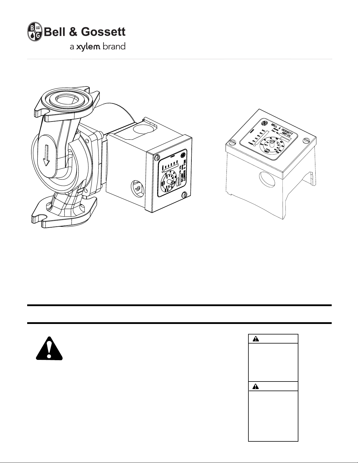
Variable Speed NRF-VS Control with
setpoint or external signal follower
INSTALLER: PLEASE LEAVE THIS MANUAL FOR THE OWNER’S USE.
WARNING
SAFETY
INSTRUCTION
This safety alert symbol will be used in this manual and on the
pump Safety Instruction decal to draw attention to safety
related instructions. When used, the safety alert symbol means
ATTENTION! BECOME ALERT! YOUR SAFETY IS
INVOLVED! FAILURE TO FOLLOW THESE INSTRUCTIONS
MAY RESULT IN A SAFETY HAZARD.
Your NRF-VS Control should have the warning/caution label
displayed to the right (Fig. 1) on the pump conduit box. If this
warning and caution label is missing or illegible, contact your
local B&G Representative for a replacement.
FIG. 1
BEFORE INSTALLING,
USING OR SERVICING
THIS PRODUCT, READ
THE INSTRUCTIONS
TO REDUCE RISK OF
ELECTRICAL SHOCK, SEE
INSTRUCTIONS FOR
PROPER INSTALLATION.
CAUTION
FOR SUPPLY CONNEC-
TIONS USE WIRE SUITABLE FOR AT LEAST
90ºC. USE COPPER
CONDUCTORS ONLY.
EMPLOYER DES FILS
D’ALIMENTATION
ADEQUATS POUR 90°C.
FOR INDOOR USE ONLY.
EMPLOYER UNIQUEMENT
AL’INTERIEUR.
Page 2
REQUIREMENTS
ELECTRICAL SAFETY
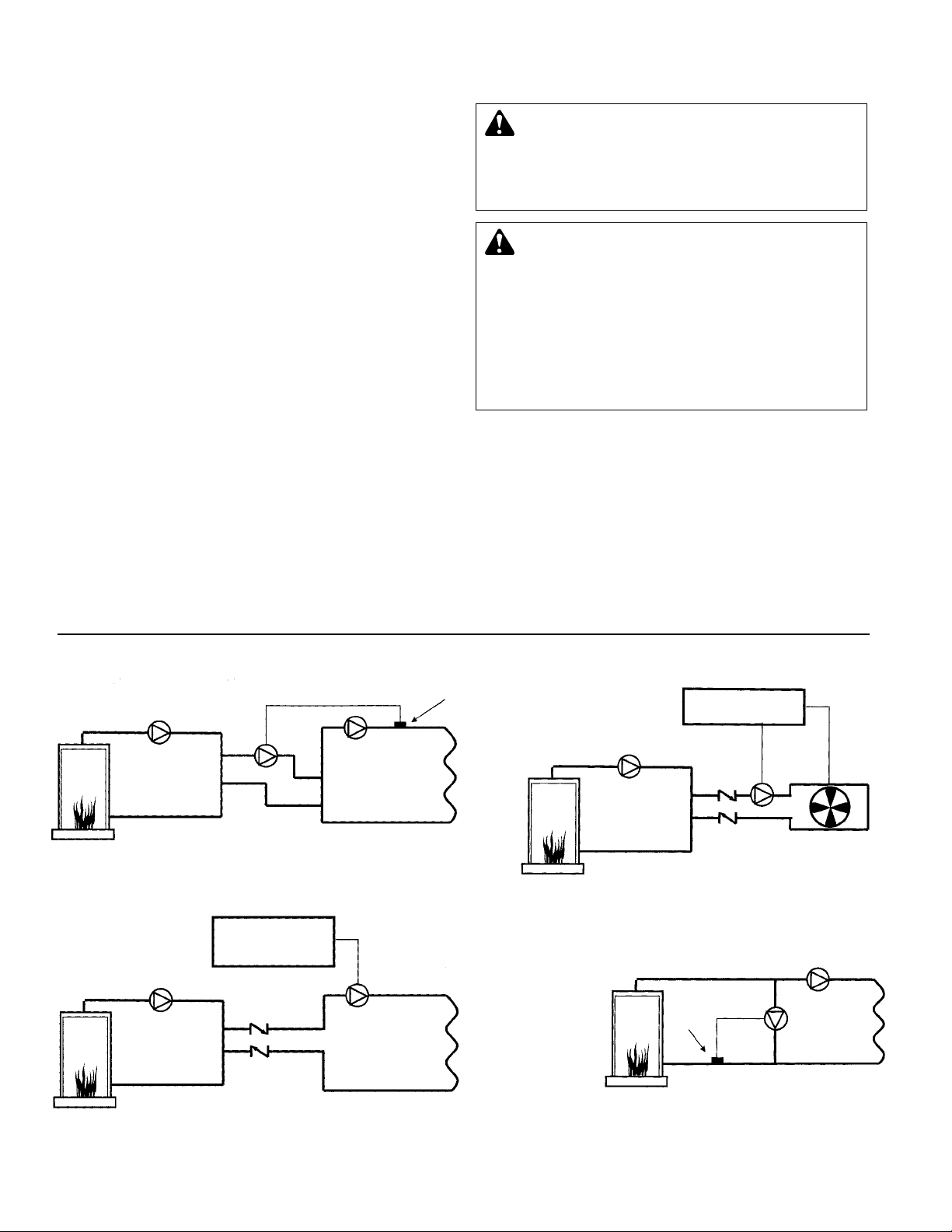
TYPICAL APPLICATIONS
WARNING: ELECTRICAL SHOCK HAZARD
Electrical connections are to be made by a qualified
electrician in accordance with all applicable codes, ordinances and good practices. Failure to follow these instructions could result in serious personal injury, death and/or
property damage.
WARNING: ELECTRICAL GROUNDING HAZARD
Adequate electrical grounding is required for the safe
operation of B&G Pumps. The use of grounded metal conduit assures this requirement. If means of connection to the
supply – connection box (wiring compartment) is other than
grounded metal conduit, ground the pump back to the
service. Use a copper conductor at least the size of the
circuit connectors supplying the pump. Connect the ground
wire to the green grounding screw in the wiring compartment. Failure to follow these instructions could result in
serious personal injury, death and/or property damage.
PRIMARY-SECONDARY WITH FAN COIL
PRIMARY
LOOP
Boiler
NRF-VS
Building
Management System
Boiler
Boiler
Sensor
NRF-VS
BYPASS BOILER INJECTION
Secondary Loop
Sensor
SECONDARY
LOOP
NRF-VS
PRIMARY
LOOP
Boiler
PRIMARY-SECONDARY INJECTION
SECONDARY
LOOP
PRIMARY
LOOP
Boiler
PRIMARY-SECONDARY
NRF-VS
Variable Speed
Control or Building
Management System
2
DESCRIPTION
The NRF-VS is a variable speed control for use in hydronic
heating and cooling applications. The temperature of the
water is controlled by regulating the speed of the pump which
injects water from a different temperature water loop (Primary
loop) into a controlled loop (Secondary loop). As the speed of
the pump increases, more water is sent into the Secondary
loop, resulting in a secondary loop water temperature change.
The NRF-VS can be used either to receive an external 4-20mA
or 2-10V signal to control the pump speed. This allows the
control to regulate the pump speed to match the input signal
supplied.
The NRF-VS can also be used as a set point control. In this
mode of operation, the NRF-VS will control the pump speed to
hold a constant temperature (determined by the user) in the
Secondary loop. The NRF-VS is capable of reading the loop
temperature sensor. When used in a heating application, if
the loop temperature falls below an adjustable setting, the
NRF-VS will increase the speed of the injection pump.
In addition, the NRF-VS can be used in cooling applications. In
this senario, the NRF-VS wil increase pump speed whenever
the loop temperature increases above the setpoint.
OPERATIONAL LIMITS
These controls are to be used on pumps designed to pump
liquids compatible with their cast iron, bronze or stainless
steel body constructions.
Maximum Operating Pressure: 150 PSI (10 bars).
Maximum Operating Temperature: 240ºF cast iron body,
230ºF brass and stainless steel body.
Electrical Rating: 115V, 60HZ, 1Ø.
Suitable for NRF, NBF, and SSF pumps with less than 1.1
amps pump nameplate rating.
Page 3
OPERATION
The NRF-VS is designed to control the pump speed on an
injection system allowing the pump to inject a different water
temperature into a secondary loop to regulate its temperature.
It can be used either in heating or cooling applications using a
secondary loop temperature sensor. The sensor reads the
secondary loop temperature allowing the NRF-VS to regulate
the loop temperature by modulating the injection pump speed
accordingly to reach a set point.
A temperature knob mounted on the NRF-VS is used to adjust
the temperature set point either in heating or cooling (see Dip
Switch 2). Dip Switch 1 must be set to ON to activate the Set
Point feature. The sensor must be wired to terminals 2 and 3
when using the setpoint mode.
The NRF-VS can be controlled remotely using an external
signal to replace the set point. This allows for the external
control or system providing the input to change the pump
speed directly. No sensor is required in this setting. The
external input providing either 4-20mA signal or 2-10V signal
must be wired to terminals 1 and 2. The speed of the pump
will vary from full stop below 4mA or 2V to 100% at 20mA or
10V. Dip switch 1 must be set OFF to activate the external
signal feature.
DESIGN SELECTION
To select the correct pump, pipe size and balance valve:
1.Determine the Primary Loop Temperature. This is the
temperature the primary loop will maintain.
2. Determine the Secondary Loop Temperature. This is the
design temperature of the secondary loop. If an outdoor
reset function is being employed, this is the required
temperature of the secondary loop under maximum load.
3. Determine the design temperature drop (
T or delta T) of
the secondary loop. This is the design drop in temperature through the secondary loop. In most radiant
heat applications,
T is 10. Other types of radiation such
as baseboard have a higher design
T.
4. Determine the Maximum Injection Heat Load. This is the
maximum heat requirement of the secondary loop. The
maximum injection heat load is based on the injection
pump running at the highest speed. As the pump speed
is reduced, less heat will be delivered to the secondary
loop.
5. Use the equation below to determine the design injection
flow rate.
Design Injection Flow Rate (GPM) =
Maximum Injection Heat Load (BTU/hr)
500 (T
primary - Tsecondary + Tsecondary) (ºF)
6. Use the table below to select the appropriate pump, pipe
size and balance valve.
Design Injection Injection B&G Circuit Setter
®
B&G Circuit Setter
®
B&G
Flow Rate (GPM) Pipe Size Balance Valve Valve Setting Pump
1.5
1
/2" CB-1/2 / CB-1/2S 18 / 25 NRF-22
3.5
1
/2" CB-1/2 / CB-1/2S full open / 6 NRF-22
6
3
/4" CB-3/4 / CB-3/4S full open / 12 NRF-22
10 1" CB-1 / CB-1S full open / full open NRF-22
15 1
1
/4" CB-11/4 / CB-11/4S 5 / 5 NRF-22
Example:
1. Primary Loop Temp: 140ºF
2. Secondary Loop Temp: 100ºF
3. Design temperature drop: 10ºF
4. Maximum injection heat load: 150,000 BTU/hr
5. Calculate Injection flow rate
Design Injection Flow Rate (GPM) =
150,000 (BTU/hr)
=
150,000
= 6 GPM
500 (140 - 100 + 10) (ºF) 25,000
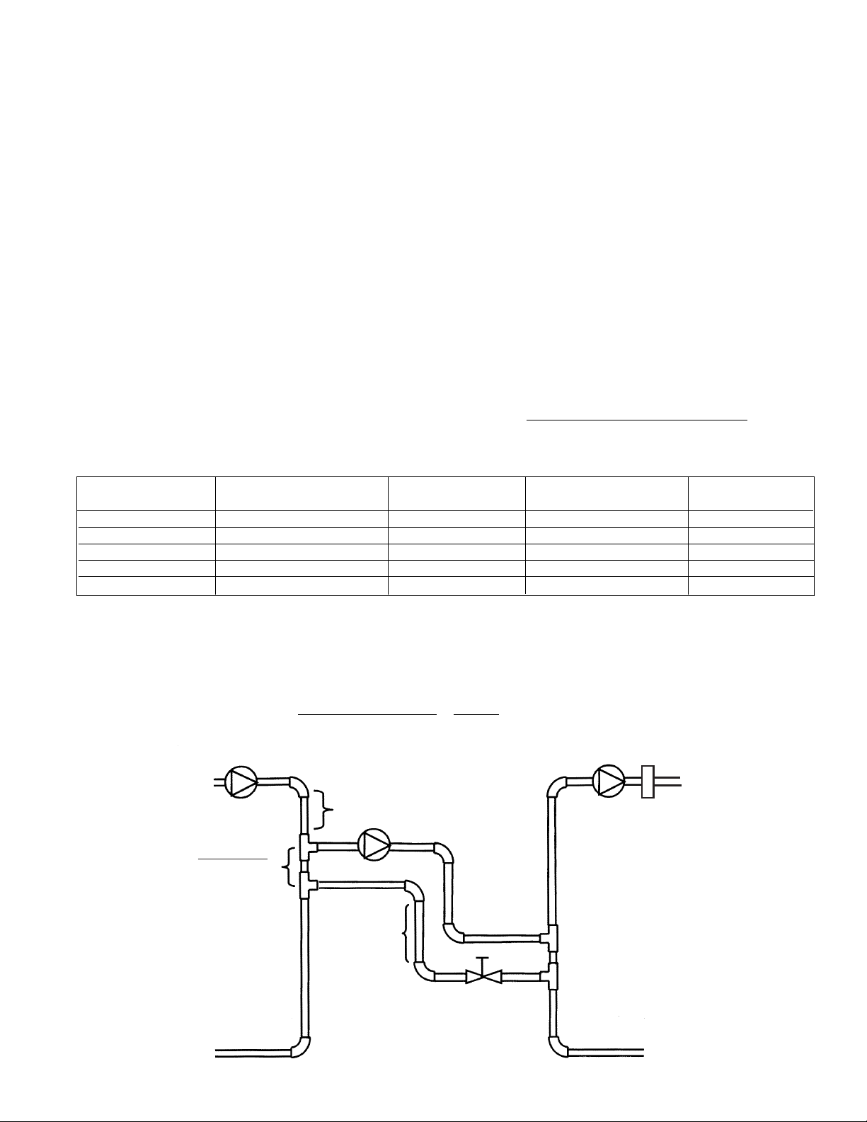
6. Injection Pipe size is
3
/4", full open CB-3/4 balancing valve and NRF-22
Minimum of 1' of
pipe drop required
to create a thermal
trap
Rule of Thumb
3 pipe diameters
between tees
Minimum of 8 pipe diameters upstream
and 4 pipe diameter downstream of straight
pipe on either side of tees to prevent any
possibility of “jet flow” through the
common piping.
Secondary
Loop
Secondary
Loop Pump
Primary
Loop Pump
Secondary
Loop Sensor
Primary
Loop
Injection Pump
Balance
Valve
3
FIG. 2
Based on (5) feet of pipe, (4) 90° elbows, (4) tees. Correct pipe and pump size calculation for any application should be performed by a qualified engineer or contractor.
Page 4

PIPING
PIPING OVERVIEW
• The Primary loop may have mulitple injection loops or other
takeoffs. However, the piping for each injection system
must meet the requirements described below.
• The Injection piping can be installed in either a horizontal or
a vertical configuration.
• The pipe diameters of the Primary and Secondary loops
may differ.
• The Injection Piping diameter must be at least one pipe size
smaller than the smaller of the Primary and Secondary loop
piping. For example, if the Primary loop diameter is 1
1
/4"
and the Secondary loop diameter is 1", then the diameter of
the Injection piping must be
3
/4" or smaller.
• The Injection pump motor must be a fractional B&G NRF,
NBF or SSF permanent split capacitor type pump. (Refer to
operational limits on Page 2 for pump information.) The
Injection pump will control the amount of water pumped
from the Primary loop into the Secondary loop.
• A balancing valve should be installed on the injection return
piping. This helps to balance the system.
• The distance between the injection tees should be as short
as possible. The rule of thumb distance between the tees is
3 times the pipe diameter. For instance, if the pipe diameter
is 1" then the length of straight pipe between the two
injection tees should be 3".
HORIZONTAL PIPING CONFIGURATION
• The Injection piping can be installed horizontally as shown
in Fig. 2.
• The Injection supply piping should run horizontally from the
Primary to the Secondary loop.
• On the Injection piping it is necessary to install a heat trap
to prevent heat from the Primary loop entering the Secondary loop when the Injection pump is not running.
• The injection piping must drop down vertically at least 18"
and then rise back up vertically at least 18".
VERTICAL PIPING CONFIGURATION
• The Injection piping can be installed vertically.
• The Primary loop must be at least 18" vertically above the
Secondary loop.
INSTALLING SENSOR
• In a primary/secondary application, the secondary loop
sensor should be mounted downstream of the inlet loop and
before any major heating units. That will provide the control
a more accurate temperature reading (Refer to Fig. 2.)
• Strap the cylindrical sensor to the pipe as shown in Fig. 3.
• Wrap the pipe and sensor assembly with insulating tape to
insure adequate heat transfer to the sensor.
• The sensor wires can be extended up to 500' from the
controller. If the sensor wires are located in an area with
strong sources of electro-magnetic interference (EMI), the
wires must be run in a grounded metal conduit. Do not run
wires in conduit with line voltage.
WIRING
NOTE: If the NRF-VS control is already installed on the pump,
skip the NRF-VS control installation section and proceed to
the “wiring the sensors” section.
NRF-VS CONTROL INSTALLATION
1. Disconnect the electrical supply to the pump.
2. Remove the screw that holds the steel conduit box cover
to the pump.
3. Remove the conduit box cover. The NRF-VS control
assembly replaces the conduit box cover.
4. Disconnect the black and white motor leads from the
power supply.
5. Position the plastic base for the NRF-VS control
assembly onto the steel conduit box with the warning/
caution label to the rear of the pump.
6. Secure the plastic base to the conduit box with one 8-32
screw provided.
7. Verify that the electrical rating of the NRF-VS control
matches the values shown on the nameplate of the
circulator.
WARNING: ELECTRICAL SHOCK HAZARD
Disconnect and lock out power before making elec-
trical connections. Failure to follow these instructions could
result in serious personal injury or death.
4
CAUTION: The Injection pump and pipe sizing
should be performed by a qualified engineer or
contractor. Failure to follow these instructions could
cause inadequate system performance and/or property
damage.
FIG. 3
Page 5

8. Make the electrical connections according to the wiring
diagram provided (See Fig. 4). Route the power wiring
through one of the
7
/8" diameter holes in the steel conduit
box. The control or sensor wiring must pass through the
7
/8" diameter hole in the plastic enclosure.
9. Attach 120VAC line voltage to the orange wire extending
from the back of the NRF-VS. Wire the neutral wire to
either of the orange wires extending from the back of the
NRF-VS.
WIRING THE SENSORS FOR SETPOINT CONTROL
• Sensor terminals are located on the back of the NRF-VS
control board.
• To set the NRF-VS for use with a temperature sensor, set
Dip Switch 1 to On.
• Pass the sensor wiring through the
7
/8" hole in the plastic
enclosure. Low voltage wiring must be separated from
power wiring.
• The sensor wires have no polarity. Connect either wire from
the sensor to terminals 2 and 3. (See Fig. 5)
• Sensors are typically installed on the secondary loop. (See
Fig. 2)
• On a sensor failure or short the pump will run at full speed
and LED Lights will blink indicating a fault status.
WIRING THE EXTERNAL SIGNAL INPUT
4-20MA OR 2-10V
• External signal terminals are located on the back of the
NRF-VS control board. (See Fig. 6).
• To wire the NRF-VS for use with an external signal either
4-20mA or 2-10V, set Dip Switch 1 to Off.
• The NRF-VS DOES NOT source current for the signal. The
current must be supplied by the control or system
supplying the signal.
• Pass the sensor wiring through the
7
/8" hole in the plastic
enclosure. Low voltage wiring must be separated from
power wiring.
• Polarity is important when using an External Signal. Always
connect the common to terminal 2 while the signal side is
connected to terminal 1.
• On a signal error the pump will fully stop and LED Lights
will blink indicating a fault status.
• When using 4-20mA input signal, make sure the input
source can supply at least 10V.
• When using 2-10V input signal, make sure the input source
can supply at least 20mA.
DIP SWITCH SETTINGS
Dip Switch 1 (Input Mode 4-20mA/2-10V or Setpoint)
1=Off (4-20mA/2-10V), 1=On (Setpoint) Default 1=Off
• This control can vary the pump speed based on either an
External Signal of 4-20mA/2-10V or a Temperature
Setpoint.
WARNING: ELECTRICAL SHOCK HAZARD
Electrical connections are to be made by a qualified
electrician in accordance with all applicable codes, ordinances and good practies. Failure to follow these instructions could result in serious personal injury, death and/or
property damage.
CAPACITOR
Black
Black
Black
Orange
Orange
Neut
Line
White
White
White
Power Switch
Surge Suppressor
5
FIG. 4
FIG. 5
FIG. 6
External Signal Wiring
123
External Signal
123
Sensor Wiring
Common
Dip Switches
Input Mode Setting
Dip Switch 1
4-20mA
2-10V
Setpoint
Temperature Sensor
Page 6

6
Setpoint (Dip Switch 1=On)
• The Dial on the NRF-VS allows for set point temperature
adjustment. Use a small screwdriver to turn the dial so that
the arrow lines up with the desired setpoint temperature.
• The pump speed will vary based on the difference between
the secondary loop sensor reading and the set point on the
NRF-VS.
External Signal (Dip Switch 1=Off)
• Below 4mA or 2V, the pump will fully stop. At 20mA or 10V
the pump will run at full speed.
• The temperature dial is deactivated when control is in the
external signal mode.
Dip Switch 2 (Control Mode Heating or
Cooling) Available with Setpoint Only
2=Off (Heating), 2=On (Cooling) Default 2=Off
• When Heating is selected, the control will increase pump
speed when the loop temperature drops further from the
Setpoint. When loop temperature is higher than the
setpoint, the control will turn off the pump. Refer to the
outer range of 70º-200ºF shown in the scale.
• In Cooling, the control will increase pump speed the higher
the loop temperature increases above the Setpoint. When
the setpoint is reached and maintained, the control will turn
off the pump. Refer to the inner range of 30º-100ºF shown
in the scale.
Dip Switch 3 (Output Mode Linear or Logarithmic)
3=Off (Linear), 3=On (Logarithmic) Default 3=Off
Linear (Dip Switch 3=Off)
Linear operation is based on a linear relationship between
percent of flow of the pump and BTU output of the terminal
unit. Typical application is when the pump injects into a
constant circulating loop, which includes the terminal unit.
Logarithmic (Dip Switch 3=On)
Logarithmic operation is based on non-linear relationship
between percent of flow of the pump and BTU output of the
terminal unit. In order to achieve the desired linear output, the
NRF-VS provides a logarithmic output to compensate for the
non-linear terminal output. Typical application is when the
pump injects directly into the terminal unit.
Dip Switch 4 (Gain) Available with Setpoint Only
4=Off (Normal), 4=On (Fast) Default 4=Off
• The Gain is how aggressive the control should behave
when loop temperature is far from Setpoint. It governs the
amount of change the control applies to pump speed.
• Normal gain is typically used in applications where the
sensor temperature changes gradually during operation.
• Fast gain is typically used in applications where the sensor
temperature changes rapidly during operation.
Dip Switch 5 (Pump Exercise)
5=On (Exercise), 5=Off (No Exercise) Default 5=On
• This Dip Switch regulates if the pump should be exercised
when stayed idle for a long period of time. When set to
Exercise, pump will run at full speed for a period of 10
seconds when left in idle status for a period of 72 hours.
Temperature Dial
Heating/Cooling Mode Setting
Dip Switch 2 (Setpoint only)
Heating Cooling
Output Mode Setting
DIP Switch 3
Linear Logarithmic
3 3
100%
BTU Output
0% 100%
100%
Terminal Unit Output
BTU Output
0% 100%
% of Flow
Linear
Desired
Output
Logarithmic
% of Flow
Logarithmic
Gain Setting
DIP Switch 4
Normal Fast
4 4
Pump Exercise Setting
DIP Switch 5
No Exercise Exercise
10 Sec every
3 idle days
Page 7

POWER UP SEQUENCE
At initial power up, the NRF-VS will run at full speed for 5
seconds. It will then run at low speed for 5 seconds, before
adjusting to the appropriate speed. Monitor the pump at initial
power up. If the pump does not operate as indicated above,
the Gain (DIP Switch 4) can be adjusted to On (Fast) to
increase the minimum power setting.
OUTPUT LIGHTS
The NRF-VS cover has 6 LED lights to indicate operation and
faulty status.
THE GREEN OUTPUT LIGHT
Represents power to the NRF-VS. When constantly On, the
control is powered.
THE RED OUTPUT LIGHTS
Represent pump speed in increments of 20%. If only one Red
light is on, the pump speed is equal to or below 20%. If 2 Red
lights are On, the pump speed is equal to or below 40%.
When 3 Red lights are On, the pump speed is equal to or
below 60%. When 4 Red lights are On, the pump speed is
equal to or below 80%. When all Red lights are On, the pump
is running from 80% to full speed.
FLASHING LIGHTS
• This indicates an error in the input signal. If NRF-VS is set
to 4-20mA/2-10V, the signal must be below 0.5mA or
0.25V. Check input signal and wiring.
• If NRF-VS is set to Set Point, the sensor has fault status,
either shorted or opened. Check sensor wires and Ohm
reading against sensor temperature chart.
PERIODIC INSPECTION
Bell & Gossett products are designed to provide years of
trouble free service. It is recommended that periodic inspections be made to check for potential problems with the pump
and control. If any leakage or evidence of leakage is present,
repair or replace the unit.
TEMPERATURE Value
(in Degrees ºF) (in 0hms)
30 17264
35 14985
40 13040
45 11374
50 9944
55 8714
60 7653
70 5941
80 4649
90 3667
100 2914
110 2332
120 1879
130 1524
140 1243
150 1021
160 842
170 699
180 583
190 489
200 412
210 349
220 297
230 253
WARNING: The NRF-VS is an operating control only.
The boiler must have all safety and limit controls
required by code. It is the responsibility of the installer to
verify that all the safety and limits are working properly
before and after the NRF-VS is installed. Failure to follow
these instructions could result inserious personal injury,
death and/or property damage.
7
TEMPERATURE
SENSOR CHART
Page 8

Xylem
1) The tissue in plants that brings water upward from the roots;
2) a leading global water technology company.
We’re 12,500 people unified in a common purpose: creating innovative solutions
to meet our world’s water needs. Developing new technologies that will improve
the way water is used, conserved, and re-used in the future is central to our work.
We move, treat, analyze, and return water to the environment, and we help people
use water efficiently, in their homes, buildings, factories and farms. In more than
150 countries, we have strong, long-standing relationships with customers who
know us for our powerful combination of leading product brands and applications
expertise, backed by a legacy of innovation.
For more information on how Xylem can help you, go to www.xyleminc.com
Xylem Inc.
8200 N. Austin Avenue
Morton Grove, Illinois 60053
Phone: (847) 966-3700
Fax: (847) 965-8379
www.xyleminc.com/brands/bellgossett
Bell & Gossett is a trademark of Xylem Inc. or one of its subsidiaries.
© 2012 Xylem Inc. P86271B May 2012
 Loading...