

Page 1
INSTRUCTION MANUAL
P86109
REVISION B
INSTALLER: PLEASE LEAVE THIS MANUAL FOR THE OWNER’S USE.
Close Coupled
Centrifugal Pumps
Page 2
2
SAFETY
INSTRUCTIONS
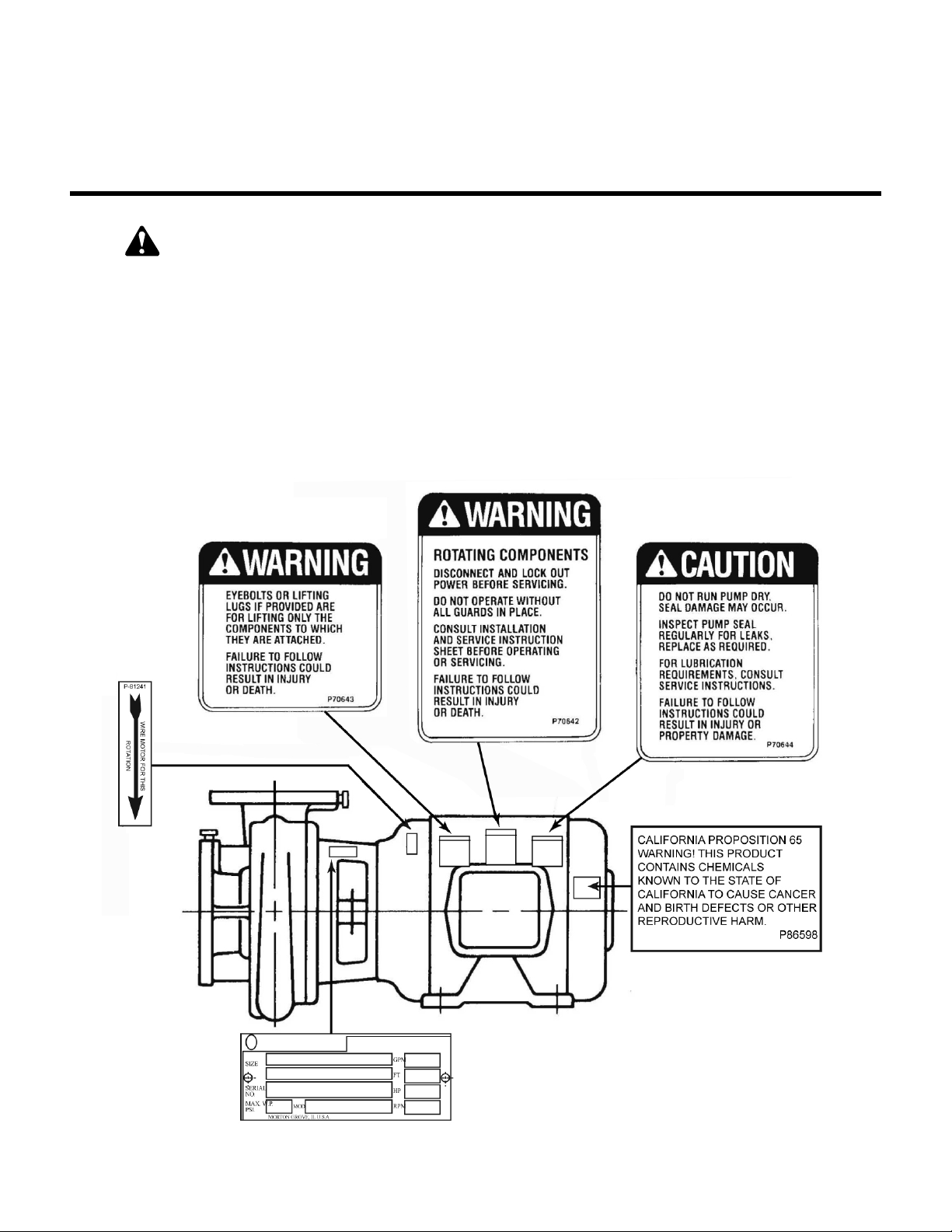
This safety alert symbol will be used in this manual and on the
pump safety instruction decals to draw attention to safety related instructions. When used the safety alert symbol means
ATTENTION! BECOME ALERT! YOUR SAFETY IS INVOLVED!
FAILURE TO FOLLOW THE INSTRUCTIONS MAY RESULT IN A
SAFETY HAZARD.
Your pump should have the following safety instruction decals
located approximately as shown. If the decals are missing or are
illegible contact your local representative for a replacement.
Additional Safety Requirements:
1. Electrical connections to be made by qualified Electrician in
accordance with all National, State and Local codes.
2. Motor must have properly sized starter with properly sized
heaters to provide overload and undervoltage protection.
3. If pump, motor or piping are operating at extremely high or
low temperatures, guarding or insulation is required.
4. The maximum working pressure of the pump is listed on the
pump nameplate, do not exceed this pressure.
DESCRIPTION
This centrifugal pump is a close coupled pump which
features – high efficiency, rugged construction, foot mounted
motor. These features make installation, operation and service
easy to perform.
PUMP APPLICATION
This centrifugal pump’s bronze fitted construction make it ideal
with service with the following liquids: fresh water, general
pumping and benign liquids.
Page 3

3
ADDITIONAL SAFETY REQUIREMENTS:
ELECTRICAL SAFETY:
THERMAL SAFETY:
MECHANICAL SAFETY:
WARNING: Electrical Shock Hazard
Electrical connections to be made by a qualified
electrician in accordance with all applicable codes, ordinances, and good practices.
Failure to follow these instructions could result in serious
personal injury or death, or property damage.
WARNING: Electrical Overload Hazard
Three phase motors must have properly sized heaters
to provide overload and undervoltage protection. Single
phase motors have built-in overload protectors.
Failure to follow these instructions could result in serious
personal injury or death, or property damage.
WARNING: Extreme Temperature Hazard
If pump, motor, or piping are operating at extremely
high or low temperatures, guarding or insulation is
required.
Failure to follow these instructions could result in serious
personal injury or death, or property damage.
WARNING: Unexpected Startup Hazard
Disconnect and lockout power before servicing.
Failure to follow these instructions could result in serious
personal injury or death, or property damage.
WARNING: Excessive System Pressure Hazard
The maximum working pressure of the pump is listed
on the nameplate, do not exceed this pressure.
Failure to follow these instructions could result in serious
personal injury or death, or property damage.
WARNING: Excessive Pressure Hazard
Volumetric Expansion
The heating of water and other fluids causes volumetric
expansion. The associated forces may cause failure of
system components and release of high temperature fluids.
This will be prevented by installing properly sized and
located compression tanks and pressure relief valves.
Failure to follow these instructions could result in serious
personal injury or death, or property damage.
PUMP LOCATION
Locate the pump so there is sufficient room for inspection,
maintenance and service. If the use of a hoist or tackle is
needed, allow ample head room.
If lifting of the entire pump is required, do so with slings placed
under the pump as shown in Figure 4.
The best pump location for sound and vibration absorption is
on a concrete floor with sub soil underneath. If the pump
location is overhead, special precautions should be undertaken to reduce possible sound transmission, consult a sound
specialist.
If the pump is not on a closed system, it should be placed as
near as possible to the source of the liquid supply, and located
to permit installation with the fewest number of bends or
elbows in the suction pipe.
The installation must be evaluated to determine that the Net
Positive Suction Head Available (NPSHA) exceeds the Net
Positive Suction Head Required (NPSHR), as stated by the
pump performance curve.
WARNING: Falling Objects Hazard
Eyebolts or lifting lugs, if provided, are for lifting only
the components to which they are attached.
Failure to follow these instructions could result in serious
personal injury or death, or property damage.
FIG. 4
IMPORTANT
Do not install and operate your pump in closed
systems unless the system is constructed with properly
sized safety devices and control devices. Such devices
include the use of properly sized and located pressure relief
valves, compression tanks, pressure controls, temperature
controls, and flow controls as appropriate. If the system
does not include these devices, consult the responsible
engineer or architect before making pumps active.
Page 4

4
INSTALLATION
This pump is built to provide years of service if installed properly and attached to a suitable foundation. A base of concrete
weighing 2
1
/2 times the weight of the pump is recommended.
(Check the shipping ticket for pump weight.)
If possible, tie the concrete pad in with the finished floor.
To facilitate easy servicing, some type of expansion fitting
should be utilized. The female portion should be inserted into a
suitable hole in the floor so that its top surface is flush with the
floor surface. Thus, when the hold-down bolts are removed, the
motor can be removed by sliding it back from the pump. (See
Figure 5)
ROTATION
Pump rotation is clockwise when viewed from back of the motor.
An arrow is provided to show direction of rotation.
PIPING
Always install a section of straight pipe between the suction
side of the pump and first elbow. This reduces turbulence of the
suction by straightening out the flow of liquid before it enters the
pump. The length should be equal to five times the diameter of
the pipe.
Be sure to eliminate any pipe-strain on the pump. Support the
suction and discharge pipes independently by use of the pipe
hangers near the pump. Line up the vertical and horizontal
piping so that the bolt-holes in the pump flanges match the boltholes in the pipe flanges. DO NOT ATTEMPT TO SPRING THE
SUCTION OF DISCHARGE LINES INTO POSITION. Bearing
wear will result if suction or discharge lines are forced into position. The code for Pressure Piping (A.S.A.B.31.1) lists many
types of supports available for various applications.
As a rule, ordinary wire or band hangers are not adequate to
maintain alignment. It is very important to provide a strong, rigid
support for the suction and discharge lines.
Where considerable temperature changes are anticipated,
fittings for absorption expansion should be installed in the
system in such a way as to avoid strain on the pump.
On an open system with a suction lift, use a foot-valve of equal
or greater area than the pump suction piping. Prevent clogging
by using a strainer at the suction inlet next to the foot-valve. The
strainer should have an area three times that of the suction pipe
with a mesh hole diameter of no less than
1
/4".
When using an isolation base, flexible piping should be used on
both the suction and discharge sides of the pump.
NOTES
1. The pipeline should have isolation valves around the pump
and have a drain valve in the suction pipe.
2. When installing the suction and discharge connection to a
threaded pump housing the use of PTFE tape sealer or a
high quality thread sealant is recommended.
PUMP INSULATION
When insulating your pump, ensure that the coverplate vent slots
and the motor remain uncovered.
FIG. 5
Page 5

5
LUBRICATION
Your pump has been lubricated at the factory, future lubrication should be in accordance with the motor manufacturers
instruction.
GENERAL INFORMATION
1. Keep the motor properly lubricated.
2. When there is a danger of freezing, drain the pump.
3. Inspect pump regularly for leaky seals or gaskets and loose
or damaged components. Replace or repair as required.
PUMP WITH STANDARD MECHANICAL SEAL
FIG. 6
Page 6

SERVICE INSTRUCTIONS
WARNING: Unexpected Startup Hazard
Disconnect and lock out power before servicing.
Failure to follow these instructions could result in serious
personal injury or death.
1. Close valves on suction and discharge sides of pump. (If no
valves have been installed, it will be necessary to drain the
system.)
CAUTION: Extreme Temperature Hazard
Check surfaces for extreme temperatures, allow
pump temperatures to reach acceptable level before proceeding. Open drain valve, do not proceed until liquid stops
coming out of drain valve. If liquid does not stop flowing
from drain valve, isolation valves are not sealing and should
be repaired before proceeding. After liquid stops flowing
from drain valve leave drain valve open and continue.
Remove the drain plug located on the bottom of the pump
volute. Do not reinstall plug or close drain valve until
reassembly is completed.
Failure to follow these instructions could result in injury or
property damage.
2. Remove motor foot capscrews. Loosen volute capscrews,
do not remove them. Use capscrews in the jack screw
holes. Start to remove the pump assembly from the volute.
CAUTION: Make certain the internal pressure is
relieved before continuing.
Failure to follow these instructions could result in injury or
property damage.
3. Remove seal flushing tube, if used.
Remove the volute capscrews and remove the pump
assembly from the volute.
4. Remove the impeller capscrew, lock washer and washer.
Remove the impeller.
5. Remove the rotating portion of the seal, use a screwdriver
to loosen the rubber ring.
6. Remove the seal insert along with the insert gasket.
7. Thoroughly clean the shaft sleeve and the coverplate seal
cavity. Inspect for surface damage like pitting, corrosion,
nicks or scratches. Replace if necessary.
8. Lubricate the shaft sleeve and coverplate seal cavity with
soapy water. (Do not use petroleum lubricant.) Install a new
cup gasket and a new seal insert with indentation side
down into the cup.
9. Slide a new rotating seal assembly onto the shaft sleeve.
With a screwdriver push on the top of the compression ring
until the seal is tight against the seal insert. Install seal
spring.
10. Install impeller, impeller washer, lock washer and capscrew,
then tighten capscrew (per torque chart).
11. Install new volute gasket then install pump assembly into
volute. Tighten volute capscrews (per torque chart). Install
seal flushing tube, if used. Install motor foot capscrews and
tighten. Install drain plug, close drain valve.
12. Open isolation valves, inspect pump for leaks, if not leaking
return pump to service.
CAPSCREW TORQUE (FOOT-POUND)
Capscrew Head
Type Marking
SAE Grade 2 6 13 25 38 60 20 190 210 300
Brass
Stainless Steel or
SAE Grade 5 10 20 35 60 90 180 325 525 800
1
/4
4 10 17 27 42 83 130 200 300
5
/16
3
/8
Capscrew Diameter
7
/16
1
/2
5
/8
3
/4
7
/8 1
DEALER SERVICING
If trouble occurs that cannot be rectified contact your local
representative. He will need the following information in order to
give you assistance.
Xylem Inc.
8200 N. Austin Avenue
Morton Grove, Illinois 60053
Phone: (847) 966-3700
Fax: (847) 965-8379
www.xyleminc.com/brands/bellgossett
Bell & Gossett is a trademark of Xylem Inc. or one of its subsidiaries.
© 2013 Xylem Inc. P86109C February 2013
1. Complete nameplate data of pump and motor.
2. Suction and discharge pipe pressure gauge readings.
3. Ampere draw of the motor.
4. A sketch of the pump hook-up and piping.
 Loading...