

Page 1
INSTRUCTION MANUAL
P85626C
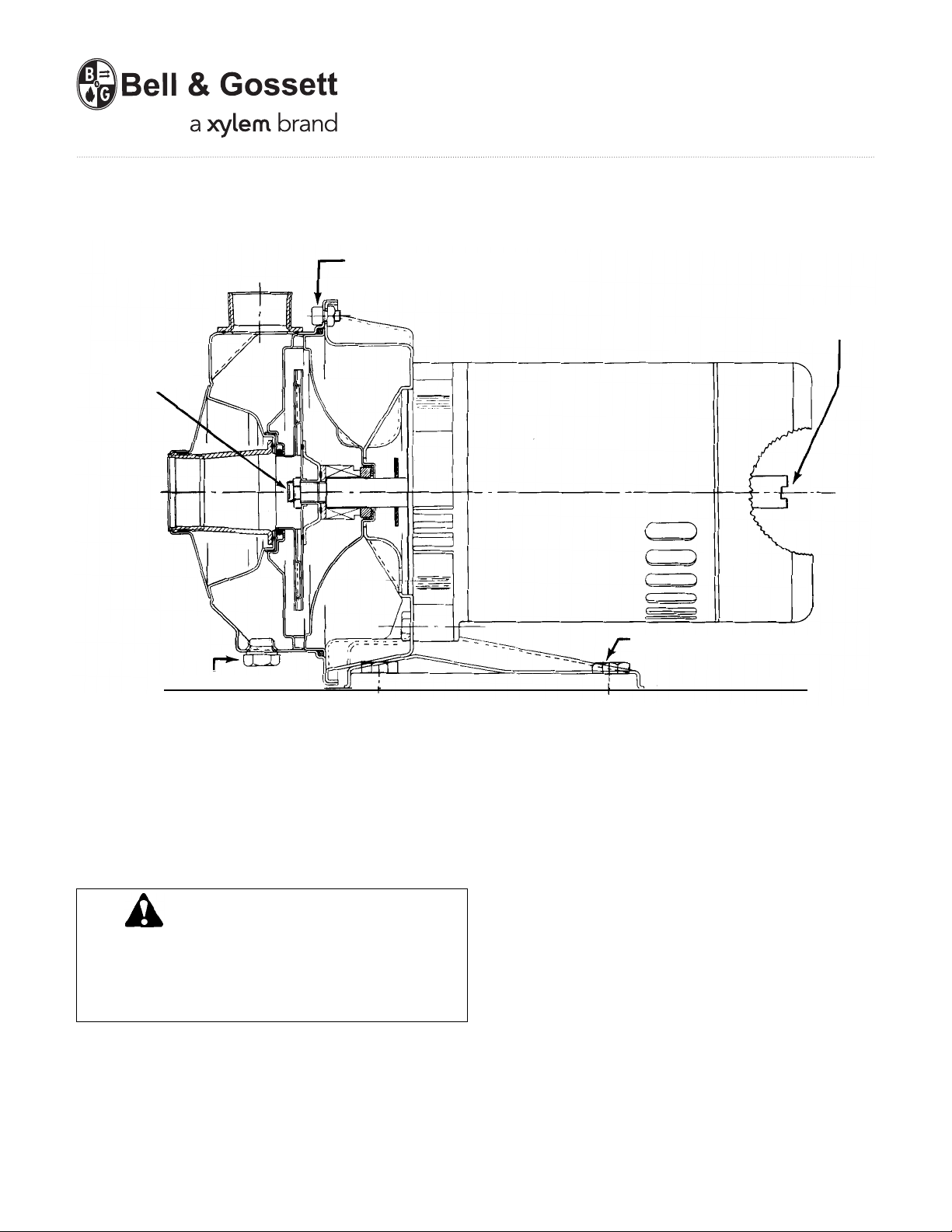
FIGURE 1
IMPELLER
LOCKNUT
PUMP DRAIN PLUG
PUMP CASING CAPSCREWS
MOTOR
SHAFT SLOT
MOUNTING CAPSCREWS
Replacement Seal Instructions for
Series 3530 Centrifugal Pumps
SAFETY
INSTRUCTIONS
This safety alert symbol will be used in this manual to draw
attention to safety related instructions. When used, the safety
alert symbol means ATTENTION! BECOME ALERT! YOUR
SAFETY IS INVOLVED! FAILURE TO FOLLOW THESE INSTRUCTIONS MAY RESULT IN A SAFETY HAZARD.
NOTE: For additional information and instructions refer to the
Installation Operation & Service Instructions Manual supplied
with your pump, or obtain a copy from your local Bell & Gossett
representative.
Page 2
SERVICE INSTRUCTIONS
WARNING: Unexpected Start Up Hazard
Disconnect and lockout power before servicing. Failure
to follow these instructions could result in serious personal
injury or death.
1. Close valves on suction and discharge sides of pump. (If no
valves have been installed, it will be necessary to drain the
system.)
CAUTION: Extreme Temperature Hazard
Allow pump temperature to reach acceptable level
before proceeding. Open drain valve, do not proceed until
liquid stops coming out of drain valve. If liquid does not
stop flowing from drain valve isolation valves are not sealing and should be repaired before proceeding. After liquid
stops flowing from drain valve, leave drain valve open and
continue. Remove the drain plug located on the bottom of
the pump housing. Do not reinstall plug or close drain
valve until reassembly is completed. Failure to follow these
instructions could result in moderate personal injury or
property damage.
2. Remove the capscrews holding the pump foot to the floor/
base. Loosen all 8 capscrews holding the motor bracket to the
pump casing, do not remove. Start to pull the motor assembly
out of the pump casing. Remove the 8 pump casing capscrews and remove the motor assembly.
WARNING: Excessive System Pressure Hazard
Make certain the internal pressure is relieved before
continuing. Failure to follow these instructions could result
in serious personal injury or death and property damage.
3. Remove the shaft cover from the back of the motor to expose
the slot in the motor shaft. (Depending on motor manufacturer, the shaft cover may be a button plug or a total cover.)
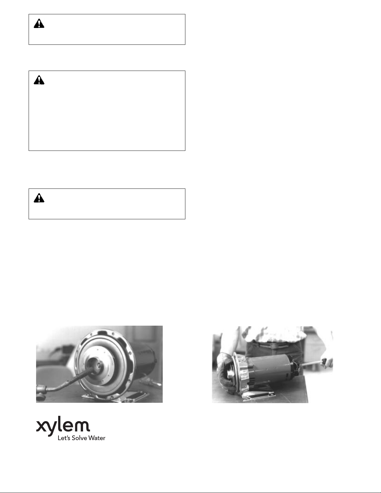
Impeller removal on pumps without impeller locknuts: The
impeller hub must be heated to break the adhesive bond so
the impeller can be removed from the motor shaft. Using a
propane torch, heat the impeller hub from the inside of the
impeller eye, Figure 4. With a glove on one hand, grip the
impeller O.D. and turn counterclockwise while holding the
motor shaft with a large screwdriver, Figure 5. Remove the
impeller, the seal spring, the seal head (use a screwdriver if
necessary), and the coverplate. Impeller removal for pumps
with impeller lockout: While holding the motor shaft with a
large screwdriver remove the impeller locknut and then the
impeller. The locknut adhesive may cause the impeller to
be hard to remove. If so, heat can be applied.
4. Remove the seal insert and the seal cup from the coverplate.
5. Thoroughly clean the shaft and the coverplate seat area.
Inspect for surface damage like pitting, corrosion, nicks or
scratches. Replace if necessary.
6. Lubricate the shaft and the coverplate seat with soapy
water (do not use petroleum lubricant). Install a new seal
cup and seal stationary seat into the coverplate.
NOTE: Install the indentation side of the stationary seat
into the cup.
7. Install coverplate onto motor bracket and install rotating seal
assembly.
NOTE: Place replacement seal on as far as possible by hand.
Then, using a screwdriver, press down firmly all around the
outer edge of the top compression ring until the seal is
tight against the face of the seal stationary seat.
8. Install the seal spring and then the impeller. While holding the
motor shaft, turn the impeller clockwise until the hub is tight
against the shaft shoulder. Do not exceed 10 ft-lbs. of torque.
The impeller locknut must be installed using Loctite Retaining
Compound 609 or equivalent. The shaft and locknut threads
must be clean, dry and free of oils and grease before applying the retaining compound. Apply the retaining compound
to the shaft threads and to the impeller locknut threads.
Torque locknut to 10 ft.-lbs.
IMPORTANT: The retaining compound must be allowed to
cure for at least 30 minutes before the pump is put back
into service.
Inspect coverplate O-ring, suction eye O-ring and drain and
vent plug O-rings for nicks or cuts. Replace if necessary.
®
NOTE: With a Viton
be replaced with the provided Viton
seal changeout kit, all O-rings must
®
O-rings.
9. Assemble motor to pump casing and tighten the 8 pump
casing capscrews. Tighten the pump casing capscrews in a
star pattern, do not tighten in a circular pattern. Torque casing capscrews 12 ft.-lbs. Replace the motor shaft cover.
10. Replace mounting capscrews. Replace drain and vent
plugs, close drain valve. Check for proper motor rotation.
11. Open isolation valves, inspect coverplate O-ring and mechanical seal for leaks. If not leaking, return pump to service.
FIGURE 4 – Heat impeller hub to break adhesive bond. FIGURE 5 – Remove impeller.
Xylem Inc.
8200 N. Austin Avenue
Morton Grove, Illinois 60053
Phone: (847) 966-3700
Fax: (847) 965-8379
www.xyleminc.com/brands/bellgossett
Bell & Gossett is a trademark of Xylem Inc. or one of its subsidiaries.
© 2012 Xylem Inc. P85626C May 2012
 Loading...