

Bell & Gossett P81875G User Manual
INSTRUCTION MANUAL
381875
REVISION G
INSTALLER: PLEASE LEAVE THIS MANUAL FOR THE OWNER’S USE.
Series HSC and HSC-S
Base Mounted
Centrifugal Pumps
BELL & GOSSETT PUMP
MODEL
NO.
SERIAL
NO.
IDENT.
NO.
G.P.M. FT. HP R.P.M.
P.S.I.
MAX.
WORK
PRESS.
6 x 8 x 12M
HSC-S 12.4 LHR 1234567 K99
1250
125
60 1800
175
PUMP
SERIES
DUTY
POINT
MAXIMUM
WORKING PRESSURE
PUMP
SIZE
SERIAL
NUMBER
MONTH
AND YEAR
DRIVER
HP-60
IMPELLER DIAMETER
12.4"
LEFT HAND
ROTATION
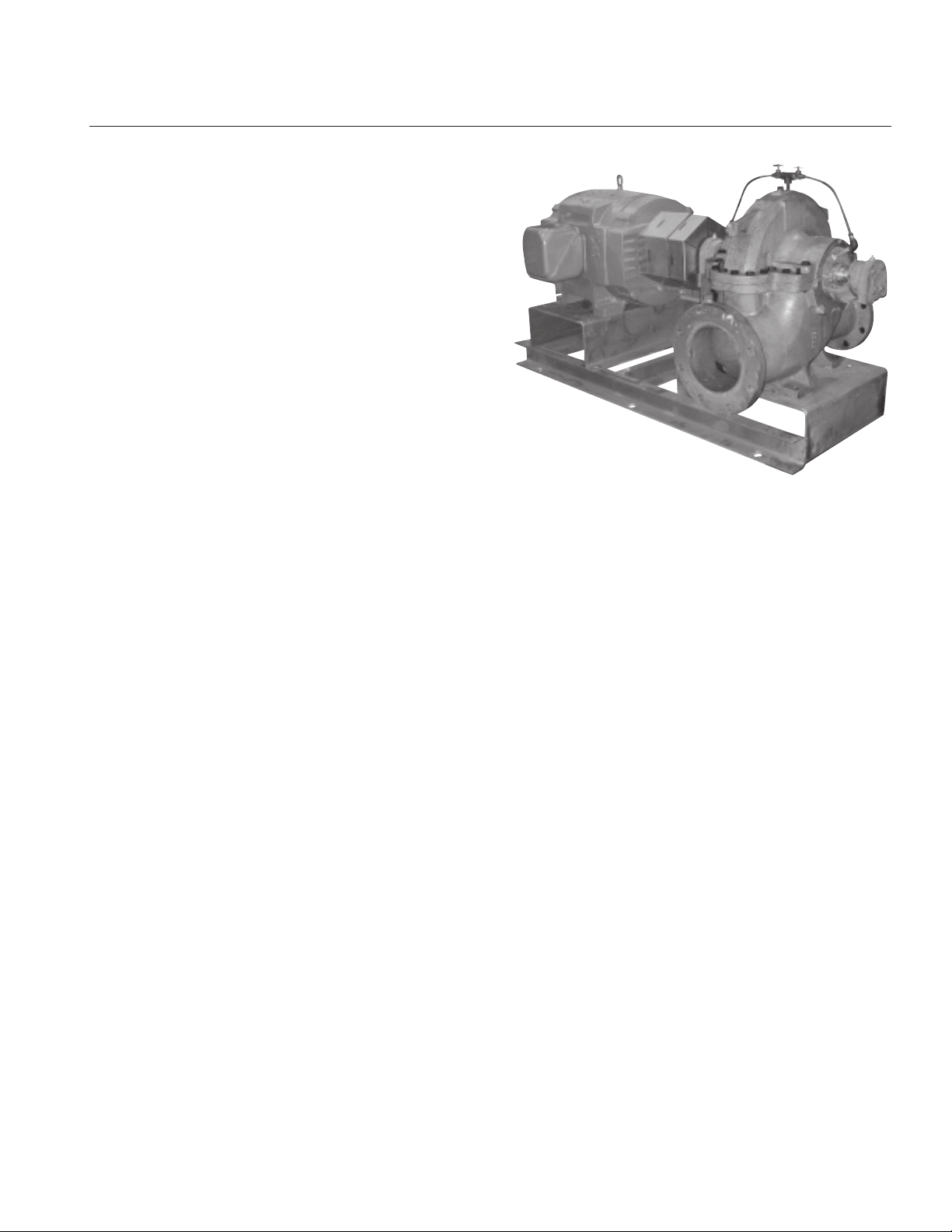
DESCRIPTION
The HSC and HSC-S Series centrifugal pumps are frame
mounted pumps which feature – high efficiency, rugged construction, compact design, foot mounted volute, center drop
out coupler, and regreasable bearings. These features, along
with the horizontal split case, make installation, operation, and
service easy to perform.
PUMP APPLICATION
The standard HSC and HSC-S Series centrifugal pump’s
bronze fitted construction make it ideal for service with the
following liquids: unheated domestic and fresh water, boiler
feed water, condensate, hydronic cooling or heating, pressure
boosting, general pumping and benign liquids.
For other applications contact your local B&G representative.
OPERATIONAL LIMITS
Unless special provisions have been made for your pump by
Bell & Gossett, the operational limits for HSC and HSC-S Series
Pumps are as follows:
Maximum Working Pressure,
Listed on pump nameplate.
SEAL OPERATING LIMITS
Standard Self Flushing Mechanical Seals
BUNA-PH Limitations 7-9; Temperature Range -20 to +225°F
EPT-PH Limitations 7-11; Temperature Range -20 to +250°F
For use on closed or open systems which are relatively free of
dirt and/or other abrasive particles.
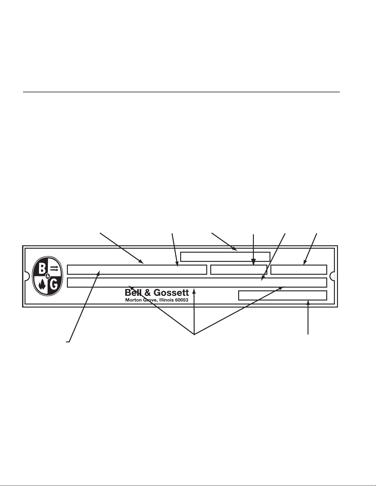
PUMP IDENTIFICATION
Bell & Gossett pumps are designated by a series of numbers
such as Series HSC and HSC-S. The pump nameplate gives
identification and rating information as identified in Illustration 1.
Permanent records for this pump are kept by the serial number
and it must be used therefore with all correspondence and
spare parts orders.
Illustration 1 – The Rating Plate
2
ADDITIONAL SAFETY REQUIREMENTS:
NYLON SLING,
CHAIN OR
WIRE ROPE
CHOKER
HITCH
AROUND
BEARING
FRAME
ELECTRICAL SAFETY:
MECHANICAL SAFETY:
WARNING: Electrical Shock Hazard
Electrical connections to be made by a qualified
electrician in accordance with all applicable codes, ordinances, and good practices. Failure to follow these instructions could result in serious personal injury or death,
or property damage.
WARNING: Electrical Overload Hazard
Three phase motors must have properly sized
heaters to provide overload and undervoltage protection.
Single phase motors have built-in overload protectors.
Failure to follow these instructions could result in serious
personal injury or death, or property damage.
THERMAL SAFETY:
WARNING: Extreme Temperature Hazard
If pump, motor, or piping are operating at extremely
high or low temperatures, guarding or insulation is required. Failure to follow these instructions could result in
serious personal injury or death, or property damage.
PUMP LOCATION
Locate the pump so there is sufficient room for inspection, maintenance and service. If the use of a hoist or tackle is needed,
allow ample head room.
WARNING: Unexpected Startup Hazard
Disconnect and lockout power before servicing.
Failure to follow these instructions could result in serious
personal injury or death, or property damage.
WARNING: Excessive System Pressure Hazard
The maximum working pressure of the pump is listed
on the nameplate, do not exceed this pressure. Do not use
air to hydrotest pump. Failure to follow these instructions
could result in serious personal injury or death, or property
damage.
WARNING: Excessive Pressure Hazard
Volumetric Expansion
The heating of water and other fluids causes volumetric
expansion. The associated forces may cause failure of system components and release of high temperature fluids.
This will be prevented by installing properly sized and
located compression tanks and pressure relief valves.
Failure to follow these instructions could result in serious
personal injury or death, or property damage.
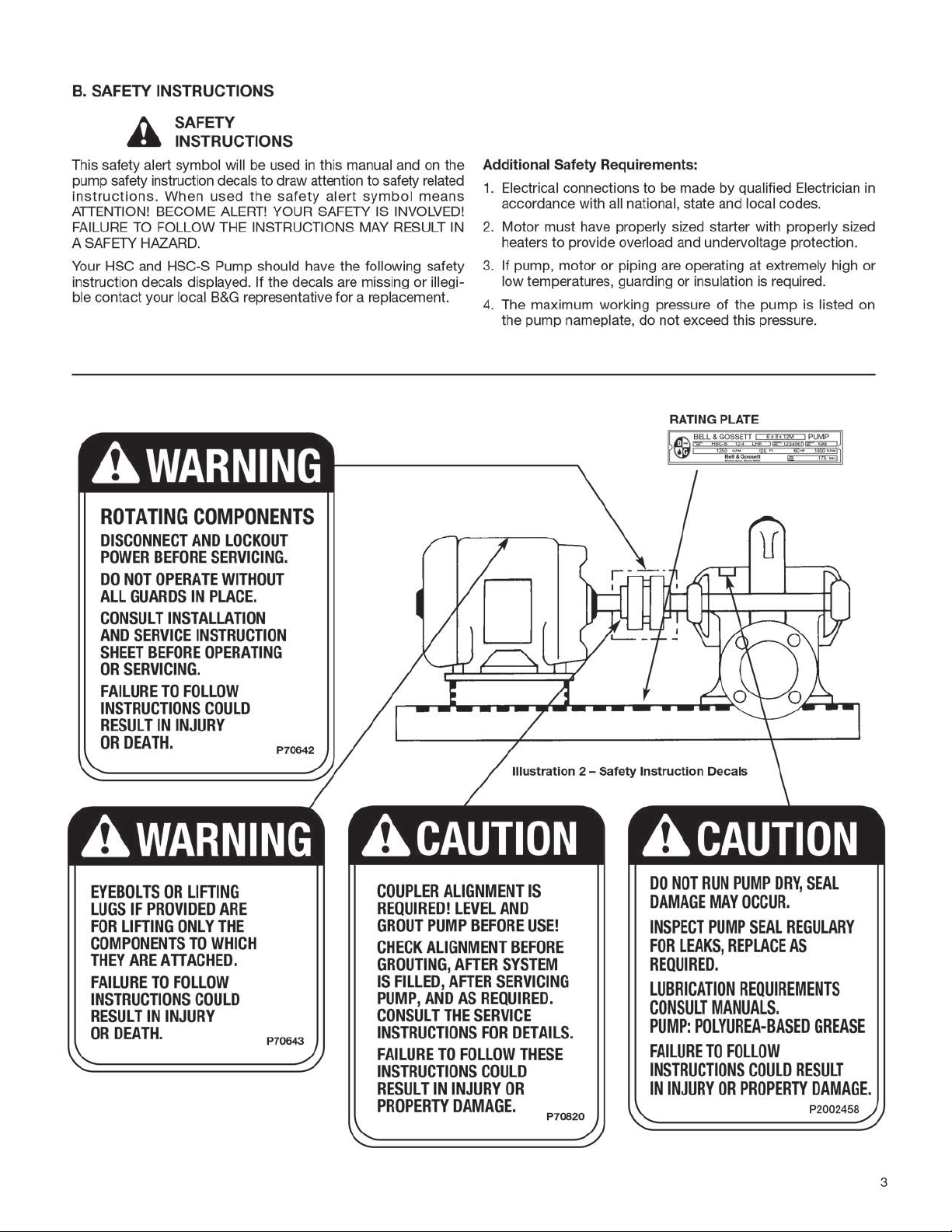
WARNING: Falling Objects Hazard
Eyebolts or lifting lugs, if provided, are for lifting only
the components to which they are attached. Failure to follow these instructions could result in serious personal
injury or death, or property damage.
If lifting base pump is required, use a nylon string, chain, or
wire rope, hitch around both bearing supports. If lifting of the
entire pump is required, do so with slings placed under the
base rails as shown.
The best pump location for sound and vibration absorption is
on a concrete floor with subsoil underneath. If the pump location is overhead, special precautions should be undertaken to
reduce possible sound transmission. Consult a sound specialist.
If the pump is not on a closed system, it should be placed as
near as possible to the source of the liquid supply, and located
to permit installation with the fewest number of bends or
elbows in the suction pipe.
COMPRESSION TANK
SHOULD BE LOCATED
ON THE SUCTION SIDE
OF THE PUMP
B&G REDUCING
COLD
WATER
SUPPLY
4
VALVE
FROM BOILER
CHILLER OR CONVERTER
B&G ROLAIRTROL
AIR SEPARATOR
ISOLATION
VALVE
SUPPLY
TO SYSTEM
B&G CIRCUIT
SETTER
B&G TRIPLE DUTY
VALVE
Illustration 3
The installation must be evaluated to determine that the Net
Positive Suction Head Available (NPSHA) meets or exceeds the
Net Positive Suction Head Required (NPSHR), as stated by the
pump performance curve. See page 9 for more details on
proper suction piping installation.
IMPORTANT
Do not install and operate Bell & Gossett Pumps, 3D Valves,
Suction Diffusers, etc., in closed systems unless the system is
constructed with properly sized safety devices and control
devices. Such devices include the use of properly sized and
located pressure relief valves, compression tanks, pressure controls, temperature controls, and flow controls as appropriate. If
the system does not include these devices, consult the responsible engineer or architect before making pumps operational.
General HSC and HSC-S Instructions
INTRODUCTION
1. Purpose of Manual
This manual is furnished to acquaint you with some of the
practical ways to install, operate, and maintain this pump.
Read it completely before doing any work on your unit and
keep it handy for future reference.
Equipment cannot operate well without proper care. To keep
this unit at top efficiency, follow the recommended installation
and servicing procedures outlined in this manual.
2. Warranty
Refer to your local representative for warranty coverage.
3. Pump Identification
All pumps are designated by Serial Number, Model Number,
and Size. This information is stamped on an identification
plate which is mounted on the pump. Refer to pump identification in specific instruction section of this manual for detailed
information.
4. Installation
5. Receiving Pump
Check pump for shortages and damage immediately upon
arrival. (An absolute must.) Prompt reporting to the carrier’s
agent with notations made on the freight bill, will expedite
satisfactory adjustment by the carrier.
Pumps and drivers normally are shipped from the factory
mounted and painted with primer and one finish coat.
Couplings may be either completely assembled or have the
coupling hubs mounted on the shafts and the connecting
members removed. When the connecting members are
removed, they will be packaged in a separate container and
shipped with the pump or attached to the base plate.
Shafts are in alignment when the unit is shipped; however, due
to shipping, the pumps may arrive misaligned and, therefore,
alignment must be established during installation. Bell &
Gossett has determined that proper and correct alignment can
only be made by accepted erection practices. Refer to the following paragraphs on “Foundation,” “Base Plate Setting,”
“Grouting Procedure,” “Alignment Procedure” and “Doweling.”
6. Temporary Storage
If the pump is not to be installed and operated soon after
arrival, store it in a clean, dry place having slow, moderate
changes in ambient temperature. Rotate the shaft periodically
to coat the bearings with lubricant and to retard oxidation,
corrosion, and to reduce the possibility of false brinelling of
the bearings.
7. Location
The pump should be installed as near the suction supply as
possible, but no less than five suction diameters (refer to page
9, suction and discharge piping section) with the shortest and
most direct suction pipe practical. The total dynamic suction
lift (static lift plus friction losses in suction line) should not
exceed the limits for which the pump was sold.
The pump must be primed before starting. Whenever possible,
the pump should be located below the fluid level to facilitate
priming and assure a steady flow of liquid. This condition provides a positive suction head on the pump. It is also possible
to prime the pump by pressurizing the suction vessel.
When installing the pump, consider its location in relation to
the system to assure that sufficient Net Positive Suction Head
(NPSH) at pump suction is provided. Available NPSH must
always equal or exceed the required NPSH of the pump.
The pump should be installed with sufficient accessibility for
inspection and maintenance. A clear space with ample head
room should be allowed for the use of an overhead crane or
hoist sufficiently strong to lift the unit.
NOTE: Allow sufficient space to be able to dismantle pump
without disturbing the pump inlet and discharge piping.
Select a dry place above the floor level wherever possible.
Take care to prevent pump from freezing during cold weather
when not in operation. Should the possibility of freezing exist
during a shut-down period, the pump should be completely
drained, and all passages and pockets where liquid might collect should be blown out with compressed air.
Make sure there is a suitable power source available for the
pump driver. If motor driven, electrical characteristics should
be identical to those shown on motor data plate.
8. Foundation
A substantial foundation and footing should be built to suit
local conditions. It should form a rigid support to maintain
alignment.
The foundation should be poured without interruption to within
1
/2 to 11/2 inches of the finished height. The top surface of the
foundation should be well scored and grooved before the
concrete sets; this provides a bonding surface for the grout.
5
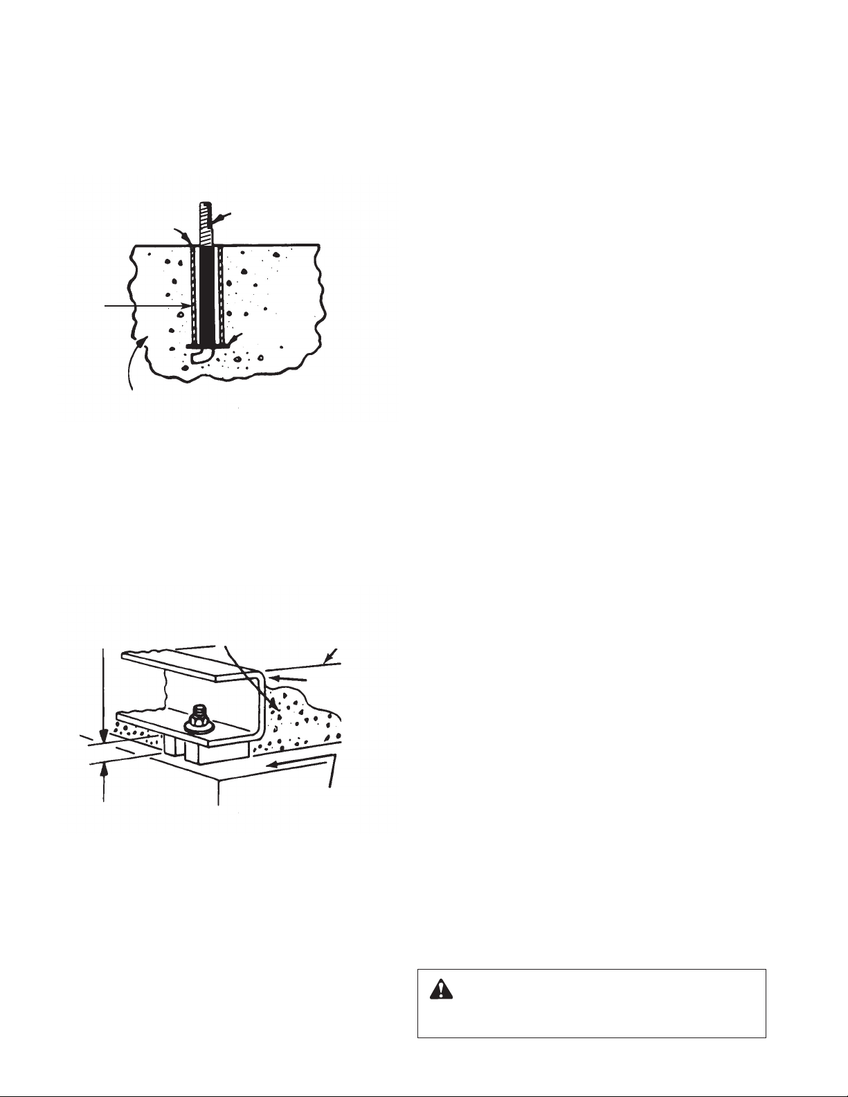
Foundation bolts should be set in concrete as shown in
Illustration 4. An optional 4-inch long tube around the bolts at
the top of the concrete will allow some flexibility in bolt alignment to match the holes in the base plate. Allow enough bolt
length for grout, shims, lower base plate flange, nuts and
washers. The foundation should be allowed to cure for several
days before the base plate is shimmed and grouted.
FOUNDATION
BOLT
WASHER
(OPTIONAL)
PIPE
SLEEVE
BUILT-UP
CONCRETE FOUNDATION
Illustration 4 – Foundation
9. Base Plate Setting (Before Piping)
NOTE: This procedure assumes that a concrete foundation
has been prepared with anchor or hold down bolts extending
up ready to receive unit. It must be understood that pump and
motor have been mounted and rough aligned at the factory. If
motor is to be field mounted, consult factory for recommendations. Bell & Gossett cannot assume responsibility for final
alignment.
NOTE:
TO KEEP SHIMS IN
ALLOW 1" FOR SHIMS.
PLACE ON BOTH SIDES
OF ANCHOR BOLTS.
APPROX.
1" GAP
LEVELING OF PUMP BASE
ON CONCRETE FOUNDATION.
Illustration 5 – Setting Base Plate and Grouting
PLACE ALLOW GROUT
TO FLOW AROUND
HOLD DOWN LUGS.
GROUT
CONCRETE
FOUNDATION
GROUT ONLY TO
TOP OF BASE RAIL.
PUMP
BASE RAIL
a. Use blocks and shims under base for support at anchor
bolts and midway between bolts, to position base
approximately 1" above the concrete foundation, with studs
extending through holes in the base plate.
b. By adding or removing shims under the base, level and
plumb the pump shaft and flanges. The base plate does not
have to be level.
c. Draw anchor nuts tight against base, and observe pump
and motor shafts or coupling hubs for alignment. (Temporarily remove coupling guard for checking alignment.)
6
d. If alignment needs improvement, add shims or wedges at
appropriate positions under base, so that retightening of
anchor nuts will shift shafts into closer alignment. Repeat
this procedure until a reasonable alignment is reached.
NOTE: Reasonable alignment is defined as that which is
mutually agree upon by pump contractor and the accepting
facility (final operator). Final alignment procedures are covered under “Alignment Procedures.”
e. Check to make sure the piping can be aligned to the pump
flanges without placing pipe strain on either flange.
f. Grout in base plate completely (See “Grouting Procedure”)
and allow grout to dry thoroughly before attaching piping to
pump. (24 hours is sufficient time with approved grouting
procedure.)
10. Grouting Procedure
Grout compensates for uneven foundation, distributes weight
of unit, and prevents shifting. Use an approved, non-shrinking
grout, after setting and leveling unit (See Illustration 5).
a. Build strong form around the foundation to contain grout.
b. Soak top of concrete foundation thoroughly, then remove
surface water.
c. Base plate should be completely filled with grout.
d. After the grout has thoroughly hardened, check the founda-
tion bolts and tighten if necessary.
e. Check the alignment after the foundation bolts are
tightened.
f. Approximately 14 days after the grout has been poured or
when the grout has thoroughly dried, apply an oil base paint
to the exposed edges of the grout to prevent air and moisture from coming in contact with the grout.
11. See ANSI/OSHA Coupler Guard Removal/Installation
(next page)
12. Alignment Procedure
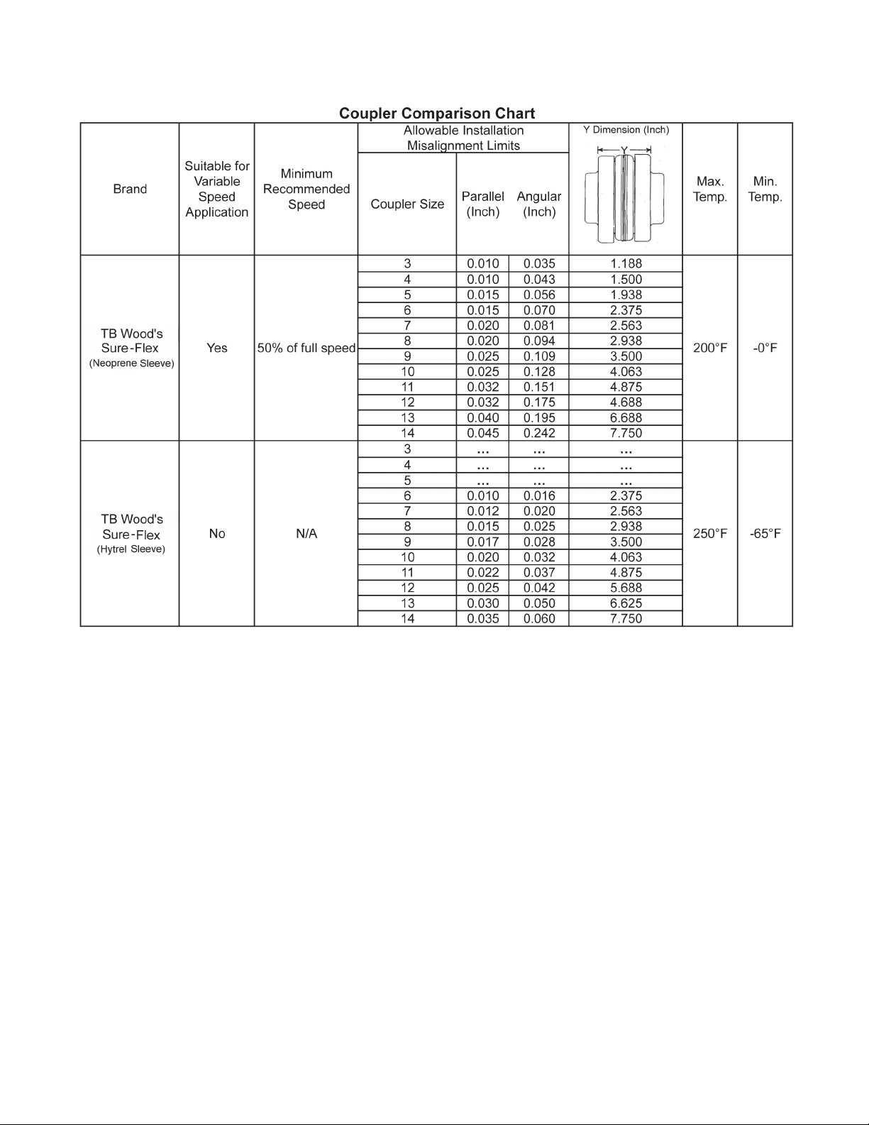
NOTE: A flexible coupling will only compensate for small
amounts of misalignment. Permissible misalignment will vary
with the make of coupling. Consult coupling manufacturer’s
data when in doubt.
Allowances are to be made for thermal expansion during cold
alignment, so that the coupling will be aligned at operating
temperature. In all cases, a coupling must be in alignment for
continuous operation. Even though the coupling may be lubricated, misalignment causes excessive wear, vibration, and
bearing loads that result in premature bearing failure and
ultimate seizing of the pump. Misalignment can be angular,
parallel, or a combination of these, and in the horizontal and
vertical planes. Final alignment should be made by moving
and shimming the motor on the base plate, until the coupling
hubs are within the recommended tolerances measured in
total run-out. All measurements should be taken with the
pump and motor foot bolts tightened. The shaft of sleeve
bearing motors should be in the center of its mechanical float.
NOTE: Proper alignment is essential for correct pump operation. This should be performed after base plate has been
properly set and grout has dried thoroughly according to
instructions. Final alignment should be made by shimming
driver only. Alignment should be made at operating
temperatures.
WARNING: Unexpected Start-up Hazard
Disconnect and lock out power before servicing.
Failure to follow these instructions could result in serious
personal injury or death and property damage.
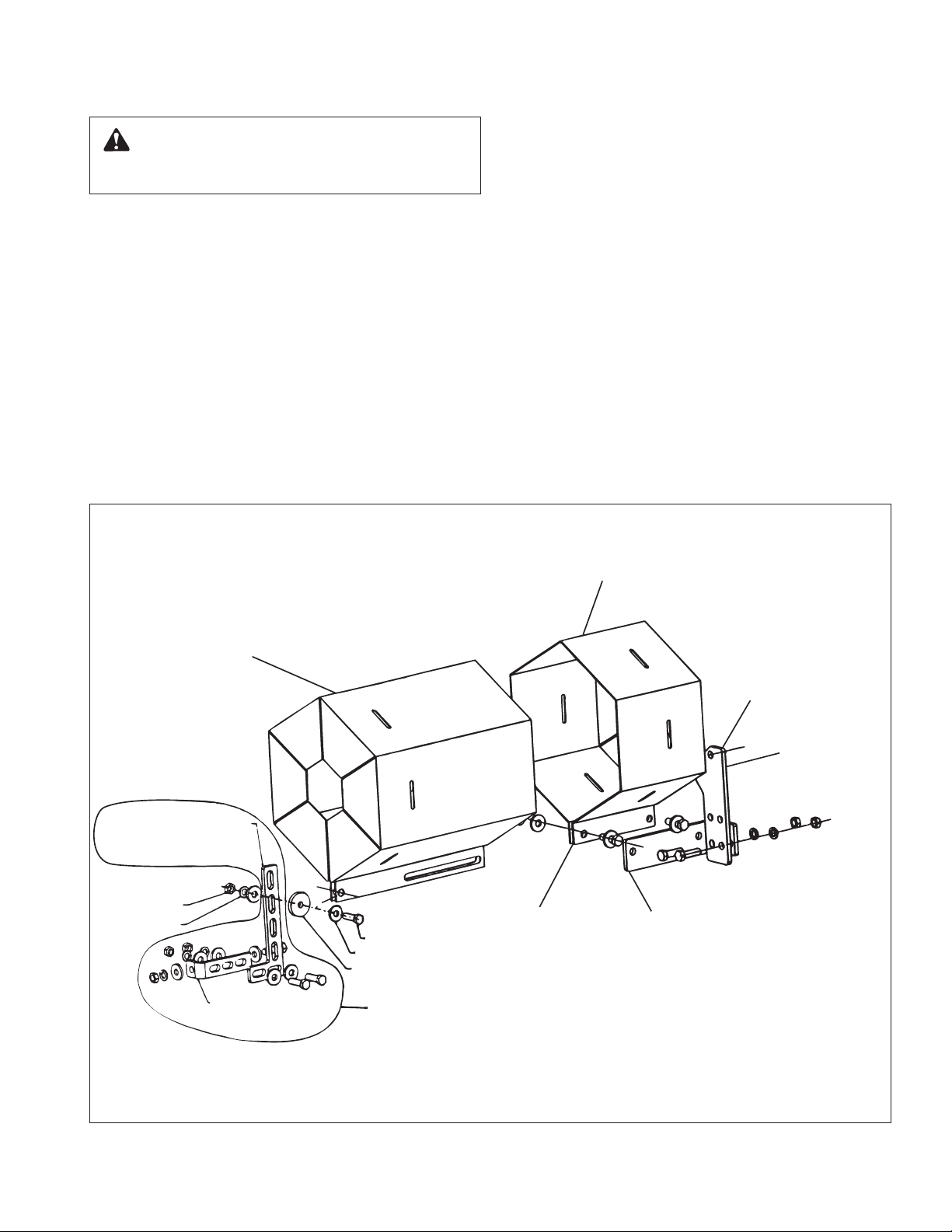
11. ANSI/OSHA COUPLER GUARD
INNER GUARD
ATTACH SUPPORT BRACKET
TO BEARING HOUSING
THIS OPTION USED IN PLACE OF SPACER WHERE
OVERALL LENGTH OF GUARD EXCEEDS 12 INCHES
OR GUARD WIDTH IS OVER 10 INCHES ACROSS
THE FLATS.
OUTER GUARD
NUT
LOCKWASHER
LOCATE SUPPORT ARM
BETWEEN OUTER GUARD ENDS.
ALIGN THE ARM WITH HOLES IN
THE OUTER GUARD AND HOLES IN
THE SADDLE BRACKET.
BRACKET SUPPORT
CAPSCREW
FLAT WASHER
BRACKET SUPPORT
ATTACHES INSIDE HERE
IN LINE WITH BOLT
MOTOR SADDLE BRACKET
ATTACH TO MOTOR SADDLE
SPACER WASHER
SUPPORT BRACKET
REMOVAL/INSTALLATION
WARNING: Unexpected Start-up Hazard
Disconnect and lock out power before servicing.
Failure to follow these instructions could result in serious
personal injury or death and property damage.
NOTE: Do not spread the inner and outer guards more than
necessary for guard removal or installation. Over spreading the
guards may alter their fit and appearance.
Removal
a. Remove the two capscrews that hold the outer (motor side)
coupler guard to the support bracket(s).
b. Spread the outer guard and pull it off the inner guard.
c. Remove the capscrew that holds the inner guard to the
support bracket.
d. Spread the inner guard and pull it over the coupler.
Installation
a. Check coupler alignment before proceeding. Correct if
necessary.
b. Spread the inner guard and place it over the coupler.
c. With the inner guard straddling the support bracket, install a
capscrew through the hole (or slot) in the support bracket
and guard located closest to the pump. Do not tighten the
capscrew.
d. Spread the outer guard and place it over the inner guard.
e. Install the outer guard capscrews by following the step
stated below which pertains to your particular pump:
i. For pumps with a motor saddle support bracket: Ensure
the outer guard is straddling the support arm, and install
but do not tighten the two remaining capscrews.
ii. For pumps without a motor saddle support bracket:
Insert the spacer washer between the holes located
closest to the motor in the outer guard, and install, but
do not tighten, the two remaining capscrews.
f. Position the outer guard so it is centered around the shaft,
and so there is less than a 1/4" of the motor shaft exposed.
On guards that utilize a slotted support bracket, the inner
guard will have to be positioned so there is only a 1/4" of
the pump shaft exposed.
g. Holding the guard in this position, tighten the three
capscrews.
ANSI/OSHA Coupling Guard Exploded View
for Typical Series HSC and HSC-S Pump Installation
7
Method 1 – Straight Edge Alignment for Standard Sleeve
Type Coupler with Black Rubber Insert (See Illustration 6A)
1
Before aligning the coupler, make sure there is at least
/8" end
clearance between the sleeve and the two coupler halves.
1. Check angular misalignment using a micrometer or caliper.
Measure from the outside of one flange to the outside of
the opposite flange at four points 90° apart. DO NOT
ROTATE COUPLER. Misalignment up to
1
/64" per inch of
coupler radius is permissible.
2. At four points 90° apart (DO NOT ROTATE COUPLER),
measure the parallel coupler misalignment by laying a
straight edge across one coupler half and measuring the
gap between the straight edge and opposite coupler half.
Up to a
1
/64" gap is permissible.
STRAIGHT EDGE
FEELER GAGE
ANGULAR ALIGNMENT PARALLEL ALIGNMENT
INCORRECT ALIGNMENT
STRAIGHT EDGE
FEELER GAGE
CORRECT ALIGNMENT
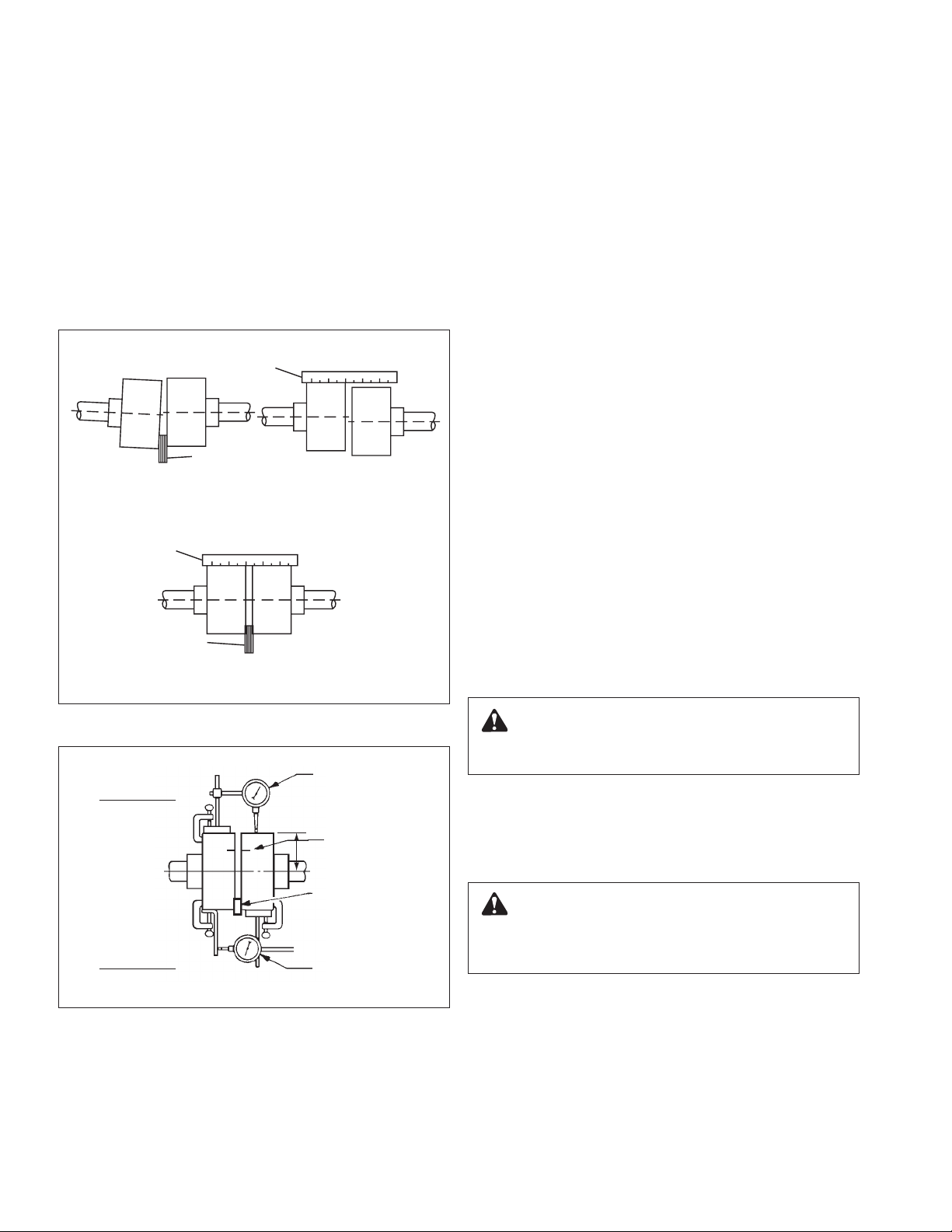
Method 2 – For Orange Hytrel Inserts, 3500 RPM
Operation, or All Other Coupler Types (See Illustration 6B)
a. Make sure each hub is secured to its respective shaft and
that all connecting and/or spacing elements are removed at
this time.
b. The gap between the coupling hubs is set by the manufac-
turer before the units are shipped. However, this dimension
should be checked. (Refer to the coupling manufacturer’s
specifications supplied with the unit.)
c. Scribe index lines on coupling halves as shown in
Illustration 5B.
d. Mount dial indicator on one hub as shown for parallel align-
ment. Set dial to zero.
e. Turn both coupling halves so that index lines remain
matched. Observe dial reading to see whether driver needs
adjustment (See paragraph i below).
f. Mount dial indicator on one hub as shown for angular align-
ment. Set dial to zero.
g. Turn both coupling halves so that index lines remain
matched. Observe dial reading to see whether driver needs
adjustment (See paragraph i below).
h. Assemble coupling. Tighten all bolts and set screw(s). It
may be necessary to repeat steps c through f for a final
check.
i. For single element couplings, a satisfactory parallel mis-
alignment is .004"T.I.R., while a satisfactory angular misalignment is .004"T.I.R. per inch of radius R (See Figure 5B).
Final Alignment
Final alignment cannot be accomplished until the pump has
been operated initially for a sufficient length of time to attain
operating temperature. When normal operating temperature
has been attained, secure the pump to re-check alignment
and compensate for temperature accordingly. See Alignment
Section.
Illustration 6A – Checking Alignment (Method 1)
PARALLEL
ALIGNMENT
ANGULAR
ALIGNMENT
Illustration 6B – Checking Alignment (Method 2)
DIAL
INDICATOR
INDEX LINE
R
RESILIENT
SEPARATOR
DIAL
INDICATOR
WARNING: Rotating Components Hazard
Do not operate pump without all guards in place.
Failure to follow these instructions could result in serious
personal injury or death and property damage.
OPTIONAL Alignment Procedure
If desired, the pump and motor feet can be doweled to the
base after final alignment is complete. This should not be
done until the unit has been run for a sufficient length of time
and alignment is within the tolerance. See Doweling Section.
CAUTION: Extreme Temperature and/or
Flying Debris Hazard
Eye protection and gloves required. Failure to follow these
instructions could result in property damage and/or moderate personal injury.
NOTE: Pump may have been doweled to base at factory.
8
9
13. DOWELING
CHECK VALVE
GATE VALVE
INCREASER
CORRECT
C OF PIPE
SUCTION PIPE INSTALLED WITH
A GRADUAL RISE TO PUMP
L
LEVEL
AIR POCKET
INCORRECT
AIR POCKET
INCORRECT
AIR POCKET
INCORRECT
GRADUAL RISE
TO PUMP
NO AIR
POCKETS
CORRECT
NO AIR
POCKETS
GRADUAL RISE
TO PUMP
ECCENTRIC
REDUCER
CORRECT
DISTANCE PLUS
ECCENTRIC REDUCER
STRAIGHTENS FLOW
CORRECT
PATH OF
WATER
INCORRECT
Dowel the pump and driving unit as follows:
a. Drill holes through diagonally opposite feet and into the
base. Holes must be of a diameter
diameter of the dowel pins. Clean out the chips.
b. Ream the holes in feet and base to the proper diameter for
the pins (light push fit). Clean out the chips.
c. Insert pins to be approximately flush with feet.
14. SUCTION AND DISCHARGE PIPING
General
When installing the pump piping, be sure to observe the following precautions:
Piping should always be run to the pump.
Do not move pump to pipe. This could make final alignment
impossible.
Both the suction and discharge piping should be supported
independently near the pump and properly aligned, so that no
strain is transmitted to the pump when the flange bolts are
tightened. Use pipe hangers or other supports at necessary
intervals to provide support. When expansion joints are used
in the piping system, they must be installed beyond the piping
supports closest to the pump. Tie bolts should be used with
expansion joints to prevent pipe strain. Do not install expansion joints next to the pump or in any way that would cause a
strain on the pump resulting from system pressure changes. It
is usually advisable to increase the size of both suction and
discharge pipes at the pump connections to decrease the loss
of head from friction.
Install piping as straight as possible, avoiding unnecessary
bends. Where necessary, use 45-degree or long sweep
90-degree fitting to decrease friction losses.
Make sure that all piping joints are air-tight.
Where flanged joints are used, assure that inside diameters
match properly.
Remove burrs and sharp edges when making up joints.
Do not “spring” piping when making any connections.
Provide for pipe expansion when hot fluids are to be pumped.
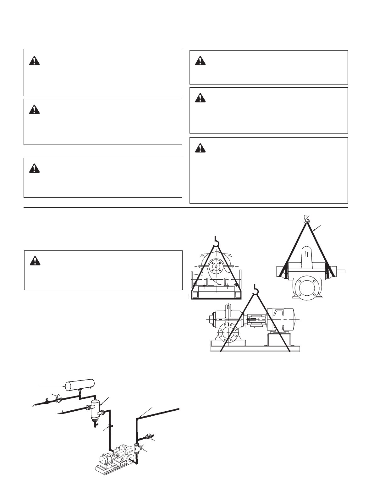
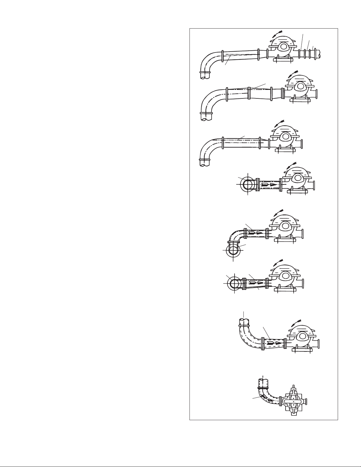
Suction Piping
When installing the suction piping, observe the following
precautions (See Illustration 7).
The sizing and installation of the suction piping is extremely
important. It must be selected and installed so that pressure
losses are minimized and sufficient liquid will flow into the
pump when started and operated. Many NPSH (Net Positive
Suction Head) problems can be attributed directly to improper
suction piping systems.
Friction losses caused by undersized suction piping can
increase the fluid’s velocity into the pump. As recommended
by the Hydraulic Institute Standard ANSI/HI 1.1-1.5-1994, suction pipe velocity should not exceed the velocity in the pump
suction nozzle. In some situations pipe velocity may need to
be further reduced to satisfy pump NPSH requirements and to
control suction line losses. Pipe friction can be reduced by
using pipes that are one to two sizes larger than the pump
suction nozzle in order to maintain pipe velocities less than
5 feet/second.
1
/64 inch less than the
10
Illustration 7 – Suction Pipe Installations
(Piping Supports Not Shown)
 Loading...