

Page 1
INSTRUCTION MANUAL
Bell & Gossett
P81845
REVISION B
Series 3530
Centrifugal Pump
Installation, Operation and Service Instructions
INSTALLER: PLEASE LEAVE THIS MANUAL FOR THE OWNER’S USE.
Bell & Gossett
Page 2
DESCRIPTION
WARNING
ROTATING COMPONENTS
DISCONNECT AND LOCK OUT
POWER BEFORE SERVICING.
DO NOT OPERATE WITHOUT
ALL GUARDS IN PLACE.
CONSULT INSTALLATION
AND SERVICE INSTRUCTION
SHEET BEFORE OPERATING
OR SERVICING.
FAILURE TO FOLLOW
INSTRUCTIONS COULD
RESULT IN INJURY
OR DEATH.
P70642
CAUTION
DO NOT RUN PUMP DRY,
SEAL DAMAGE MAY OCCUR.
INSPECT PUMP SEAL
REGULARLY FOR LEAKS,
REPLACE AS REQUIRED.
FOR LUBRICATION
REQUIREMENTS, CONSULT
SERVICE INSTRUCTIONS.
FAILURE TO FOLLOW
INSTRUCTIONS COULD
RESULT IN INJURY OR
PROPERTY DAMAGE.
P70644
The Series 3530 Centrifugal Pump is a close coupled pump
which features – foot mounting, light weight design, pump
casing with top centerline discharge and self flushing mechanical seal. These features make installation, operation and service easy to perform.
SAFETY
INSTRUCTIONS
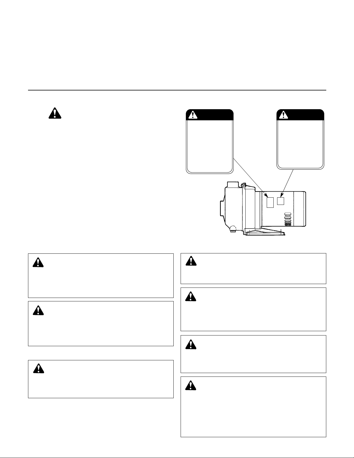
This safety alert symbol will be used in this manual and on the
pump safety instruction decals to draw attention to safety related
instructions. When used the safety alert symbol means
ATTENTION! BECOME ALERT! YOUR SAFETY IS INVOLVED!
FAILURE TO FOLLOW THE INSTRUCTIONS
A SAFETY HAZARD.
Your Series 3530 Pump should have the following safety
instruction decals located approximately as shown. If the
decals are missing or illegible contact your local B&G representative for a replacement.
MAY RESULT IN
PUMP APPLICATION
The Series 3530 Centrifugal Pump’s stainless steel construction makes it ideal for service with the following liquids:
Domestic water, fresh water
hydronic cooling or heating, pressure boosting, general pumping and benign liquids.
For other applications contact your local B&G Representative.
, boiler feed water, condensate,
ADDITIONAL SAFETY REQUIREMENTS
ELECTRICAL SAFETY:
electrician in accordance with all applicable codes,
ordinances, and good practices.
Failure to follow these instructions could result in serious
personal injury or death, and property damage.
heaters to provide overload and under voltage protection.
Single phase motors have built-in overload protectors.
Failure to follow these instructions could result in serious
personal injury or death, and property damage.
THERMAL SAFETY:
high or low temperatures, guarding or insulation is required.
Failure to follow these instructions could result in serious
personal injury or death, and property damage.
2
WARNING: Electrical Shock Hazard
Electrical connections to be made by a qualified
WARNING: Electrical Overload Hazard
Three phase motors must have properly sized
WARNING: Extreme Temperature Hazard
If pump, motor, or piping are operating at extremely
FIGURE 1
MECHANICAL SAFETY:
WARNING: Unexpected Start-up Hazard
Disconnect and lock out power before servicing.
Failure to follow these instructions could result in serious
personal injury or death, and property damage.
WARNING: Unexpected Startup Hazard
Single phase motors are equipped with automatic
reset overload protectors. Pump can restart without warning.
Disconnect and lockout power before servicing.
Failure to follow these instructions could result in serious
personal injury or death, and property damage.
WARNING: Excessive System Pressure Hazard
The maximum working pressure of the pump is listed
on the nameplate. Do not exceed this pressure.
Failure to follow these instructions could result in serious
personal injury or death, and property damage.
WARNING: Excessive Pressure Hazard
WARNING: Volumetric Expansion
The heating of water and other fluids causes volumetric
expansion. The associated forces may cause failure of system components and release of high temperature fluids. This
will be prevented by installing properly sized and located
compression tanks and pressure relief valves.
Failure to follow these instructions could result in serious
personal injury or death, and property damage.
Page 3

PUMP LOCATION
Locate the pump so there is sufficient room for inspection,
maintenance and service. If the use of a hoist or tackle is
needed, allow ample head room.
The best pump location for sound and vibration absorption is
on a concrete floor with sub soil underneath. If the pump location is overhead, special precautions should be undertaken to reduce possible sound transmission, consult a sound specialist.
If the pump is not installed on a closed system, it should be
placed as near as possible to the source of liquid supply, and
located to permit installation with the fewest number of bends
or elbows in the suction pipe.
The installation must be evaluated to determine that the Net
Positive Suction Head Available (NPSHA) meets or exceeds
the Net Positive Suction Head Required (NPSHR), as stated by
the pump performance curve.
1. IMPORTANT
1.1 Do not install and operate ITT Bell & Gossett Pumps,
3D Valves, Suction Diffusers, etc., in closed systems
unless the system is constructed with properly sized
safety devices and control devices. Such devices
include the use of properly sized and located pressure
relief valves, compression tanks, pressure contr
temperature controls, and flow controls as appropriate.
If the system does not include these devices, consult
the responsible engineer or architect before making
pumps operational.
WARNING: Excessive Pressure Hazard
WARNING: Volumetric Expansion
The heating of water and other fluids causes volumetric
expansion. The associated forces may cause failure of system components and release of high temperature fluids. This
will be prevented by installing properly sized and located
compression tanks and pressure relief valves.
Failure to follow these instructions could result in serious
personal injury or death, and property damage.
1.2 Inspect unit for damage. Report any damage to
carrier/dealer immediately.
1.3 Electrical supply must be a separate branch circuit
with fuses or circuit breakers, wire sizes, etc., per
National and Local electrical codes. Install an all-leg
disconnect switch near pump.
ols,
1.6 Motor Protection
1.6.1 Single-phase: Thermal protection for singlephase units is sometimes built in (check nameplate). If no built-in protection is provided, use
a contactor with a proper overload. Fusing is
permissible.
1.6.2 Three-phase: Pr
properly sized magnetic starter and thermal
overloads.
1.7 Maximum Operating Limits:
Liquid Temperature: 212°F (100°C) with standard seal.
Pressure: 125 PSI.
Starts Per Hour: 20, evenly distributed.
1.8 Regular inspection and maintenance will increase ser
vice life. Base schedule on operating time. Refer to
Section 8.
ovide three-leg protection with
250°F (120
temp seal.
°C) with optional high
2. INSTALLATION
2.1 General
2.1.1 Locate pump as near liquid source as possible
(below level of liquid for automatic operation).
2.1.2 Protect from freezing or flooding.
2.1.3 Allow adequate space for servicing and ventilation.
2.1.4 All piping must be supported independently of
the pump, and must “line-up” naturally.
CAUTION: Never draw piping into place by forcing
the pump suction and discharge connections.
Failure to follow these instructions could result in serious
personal injury or death, and property damage.
2.1.5 Avoid unnecessary fittings. Select sizes to keep
friction losses to a minimum.
2.2 Units may be installed horizontally, inclined or vertically.
CAUTION: Do not install with motor below pump.
Any leakage or condensation will affect the motor.
Failure to follow these instructions could result in serious
personal injury or death, and property damage.
-
CAUTION: Always disconnect electrical power
when handling pump or controls.
Failure to follow these instructions could result in serious
personal injury or death, and property damage.
1.4 Motors must be wired for proper voltage. Motor wiring
diagram is on motor nameplate. Wire size must limit
maximum voltage drop to 10% of nameplate voltage at
motor terminals, or motor life and pump performance
will be lowered.
1.5 Always use horsepower-rated switches, contactor and
starters.
2.3 Foundation must be flat and substantial to eliminate
strain when tightening bolts. Use rubber mounts to
minimize noise and vibration.
2.4 Tighten motor hold-down bolts before connecting piping to pump.
3. SUCTION PIPING
3.1 Low static suction lift and short, direct, suction piping
is desired. For suction lift over 10 feet and liquid temperature over 120°F, consult pump performance curve
for Net Positive Suction Head Required.
3
Page 4

3.2 Suction pipe must be at least as large as the suction
connection of the pump. Smaller size will degrade
performance.
3.3 If larger pipe is r
(with straight side up) must be installed at the pump.
3.4 Installation with pump below source of supply:
3.4.1 Install full flow isolation valve in piping for inspec-
tion and maintenance.
CAUTION: Do not use suction isolation valve to
thr
ottle pump.
Failure to follow these instructions could result in serious
personal injury or death, and pr
3.5 Installation with pump above source of supply:
3.5.1 Avoid air pockets. No part of piping should be
higher than pump suction connection. Slope piping upward from liquid source.
3.5.2 All joints must be airtight.
3.5.3 Foot valve to be used only if necessary for prim-
ing, or to hold prime on intermittent service.
3.5.4 Suction strainer open area must be at least triple
the pipe area.
3.6 Size of inlet from liquid source, and minimum submergence over inlet, must be sufficient to prevent air
entering pump through vortexing. See Figs. 2-5.
3.7 User 3-4 wraps of Teflon tape to seal threaded
connections.
equired, an eccentric pipe reducer
operty damage.
4. DISCHARGE PIPING
4.1 Arrangement must include a check valve located
between a gate valve and the pump. The gate valve is
for regulation of capacity, or for inspection of the pump
or check valve.
4.2 If an increaser is required, place between check valve
and pump.
4.3 Use 3-4 wraps of Teflon tape to seal threaded
connections.
5. ROTA
5.1 Correct r
TION
otation is right-hand (clockwise when viewed
from the motor end). Switch power on and off quickly.
Observe shaft rotation. To change rotation:
5.1.1 Single-phase motor: Non-reversible.
5.1.2 Three-phase motor: Interchange any two power
supply leads.
6. OPERATION
6.1 Before starting, pump must be primed (free of air and
suction pipe full of liquid) and discharge valve partially
open.
CAUTION: Pumped liquid provides lubrication. If
pump is run dry, r
cal seal will be damaged. Do not operate at or near zero
flow. Ener
Liquid may flash to vapor. Rotating parts r
prevent scoring or seizing.
Failure to follow these instructions could result in serious
personal injury or death, and property damage.
gy imparted to the liquid is converted into heat.
otating parts will seize and mechani-
equire liquid to
Figure 2 Figure 3
Figure 4 Figure 5
6.2 Make complete check after unit is run under operating
conditions and temperature has stabilized. Check for
expansion of piping.
7. MAINTENANCE
7.1 Close-Coupled Unit. Ball bearings are located in and
art part of the motor. They are permanently lubricated.
No greasing required.
8. DISASSEMBLY
Complete disassembly of the unit will be described.
Proceed only as far as required to perform the maintenance work needed.
8.1 Turn off power.
8.2 Drain system. Flush if necessary.
8.3 Remove motor hold-down bolts.
8.4 Disassembly of Liquid End:
8.4.1 Remove casing bolts (370).
8.4.2 Remove back pull-out assembly from casing
(100).
4
Page 5

8.4.3 Remove impeller locknut (304).
CAUTION: Do not insert screwdriver between
impeller vanes to prevent rotation of closecoupled units. Remove cap at opposite end of motor. A
screwdriver slot or a pair of flats will be exposed. Using
them will prevent impeller damage.
Failure to follow these instructions could result in serious
personal injury or death, and property damage.
8.4.4 Remove impeller (101) by turning counter-clockwise when looking at the front of the pump.
Protect hand with rag or glove.
CAUTION: Failure to remove the impeller in a
counter-clockwise direction may damage threading
on the impeller, shaft or both.
Failure to follow these instructions could result in serious
personal injury or death, and property damage.
8.4.5 With two pry bars 180 degrees apart and inserted between seal housing (184) and the motor
adapter (108), carefully separate the two parts.
The mechanical seal rotary unit (383) should
come off the shaft with the seal housing.
8.4.6 Push out the mechanical seal stationary seat
from the motor side of the seal housing.
9. REASSEMBLY
9.1 All parts should be cleaned before assembly.
9.2 Refer to parts list to identify required replacement
items. Specify pump index or catalog number when
ordering parts.
9.3 Reassembly is the reverse of disassembly.
9.4 Observe the following when reassembling the liquidend:
9.4.1 All mechanical seal components must be in good
condition or leakage may result. Replacement of
complete seal assembly, whenever seal has been
removed, is good standard practice.
It is permissible to use a light lubricant, such as
glycerin, to facilitate assembly. Do not contaminate the mechanical seal faces with lubricant.
9.4.2 Inspect casing O-ring (513) and replace if dam-
aged. This O-ring may be lubricated with petroleum jelly to ease
9.4.3 Inspect guidevane O-ring (349) and replace if
worn.
9.5 Check reassembled unit for binding. Corr
required.
9.6 Tighten casing bolts in a star pattern to prevent O-ring
binding.
10. TROUBLE SHOOTING
MOTOR NOT RUNNING
(See causes 1 thru 6)
LITTLE OR NO LIQUID DELIVERED:
(See causes 7 thru 17)
POWER CONSUMPTION TOO HIGH:
(See causes 4, 17, 18, 19, 22)
EXCESSIVE NOISE AND VIBRATION:
(See causes 4, 6, 9, 13, 15, 16, 18, 20, 21, 22)
PROBABLE CAUSE:
1. Tripped thermal pr
2. Open circuit breaker
3. Blown fuse
4. Rotating parts binding
5. Motor wired improperly
6. Defective motor
7. Not primed
8. Discharge plugged or valve closed
9. Incorrect rotation
10. Foot valve too small, suction not submerged, inlet
screen plugged.
11. Low voltage
12. Phase loss (3-phase only)
13. Air or gasses in liquid
14. System head too high
15. NPSHA too low: Suction lift too high or suction losses
excessive. Check with vacuum gauge.
16. Impeller worn or plugged
17. Incorrect impeller diameter
18. Head too low causing excessive flow rate
19. Viscosity or specific gravity too high
20. Worn bearings
21. Pump or piping loose
22. Pump and motor misaligned
otector
CHART
ect as
CAUTION: Do not lubricant guidevane O-ring
(349). Insure it is not pinched by the impeller on
reassembly.
Failure to follow these instructions could result in serious
personal injury or death, and property damage.
5
Page 6

 Loading...