

Bell & Gossett P81673 User Manual
Installation, Operation,
and Maintenance Manual
Series 1510


Table of Contents
Introduction and Safety..................................................................................................................3
Introduction..................................................................................................................................3
Safety.............................................................................................................................................3
Safety message levels............................................................................................................. 3
Safety instruction decals......................................................................................................... 4
User safety................................................................................................................................ 5
Environmental safety...............................................................................................................7
Transportation and Storage.......................................................................................................... 8
Inspect the delivery.....................................................................................................................8
Inspect the package................................................................................................................8
Inspect the unit........................................................................................................................ 8
Lifting methods............................................................................................................................8
Storage requirements.................................................................................................................9
Product Description......................................................................................................................10
General description.................................................................................................................. 10
Operational specifications....................................................................................................... 10
Table of Contents
Installation......................................................................................................................................12
Preinstallation............................................................................................................................ 12
Pump location guidelines.....................................................................................................12
Foundation requirements.................................................................................................... 13
Piping checklist......................................................................................................................13
Pump insulation checklist.....................................................................................................14
Typical installation.................................................................................................................15
Special installation.................................................................................................................15
Install the pump, driver, and coupling................................................................................... 15
Level the base on a concrete foundation ..............................................................................16
Grout the baseplate..................................................................................................................16
Coupling alignment..................................................................................................................16
Prepare for alignment...........................................................................................................17
Align the pump using a straight edge and calipers..........................................................17
Align the pump using a dial indicator................................................................................ 18
Align the Rexnord®Omega® coupling................................................................................ 19
Maximum allowable misalignment for Rexnord Omega couplings............................... 20
Fastener torque values and maximum RPM for Rexnord Omega couplings................ 21
Final alignment...................................................................................................................... 21
Commissioning, Startup, Operation, and Shutdown...............................................................23
Preparation for startup............................................................................................................. 23
Check the rotation.................................................................................................................23
Start the pump...........................................................................................................................24
Pump operation precautions...................................................................................................24
Shut down the pump................................................................................................................ 25
Make the final alignment of the pump and driver................................................................ 25
Note on the packed pump operation.....................................................................................25
Maintenance..................................................................................................................................27
Bearing maintenance................................................................................................................27
Series 1510 Installation, Operation, and Maintenance Manual 1

Table of Contents
Regrease the grease-lubricated bearings..........................................................................27
Lubricating grease requirements........................................................................................27
Disassembly............................................................................................................................... 28
Disassembly precautions......................................................................................................28
Drain the pump......................................................................................................................28
Remove the hex coupling guard.........................................................................................28
Remove the coupling............................................................................................................29
Remove the bearing frame and impeller assembly .........................................................29
Remove the impeller.............................................................................................................30
Remove the mechanical seal (1510 and 1510-F).............................................................. 30
Remove the seal or packing rings (1510-S, 1510-D, 1510-PF, and 1510-8G)...............30
Pre-assembly inspections.........................................................................................................30
Replacement guidelines.......................................................................................................31
Shaft and sleeve inspection................................................................................................. 31
Bearing frame inspection..................................................................................................... 31
Reassembly................................................................................................................................ 31
Seal assembly........................................................................................................................ 31
Impeller installation...............................................................................................................35
Assemble the packed stuffing box (1510-PF) ...................................................................35
Reinstall the bearing frame and impeller assembly (all except 1510-8G) .................... 36
Reinstall the bearing frame and impeller assembly (1510-8G).......................................36
Install the hex coupling guard............................................................................................. 36
Capscrew torque values.......................................................................................................37
Dealer servicing ....................................................................................................................37
Product warranty...........................................................................................................................38
2 Series 1510 Installation, Operation, and Maintenance Manual
Introduction and Safety
Introduction
Purpose of this manual
The purpose of this manual is to provide necessary information for:
• Installation
• Operation
• Maintenance
CAUTION:
Read this manual carefully before installing and using the product. Improper use of the
product can cause personal injury and damage to property, and may void the warranty.
NOTICE:
Save this manual for future reference, and keep it readily available at the location of the
unit.
Introduction and Safety
Safety
WARNING:
• The operator must be aware of safety precautions to prevent physical injury.
• Operating, installing, or maintaining the unit in any way that is not covered in this
manual could cause death, serious personal injury, or damage to the equipment. This
includes any modification to the equipment or use of parts not provided by Xylem. If
there is a question regarding the intended use of the equipment, please contact a
Xylem representative before proceeding.
• Do not change the service application without the approval of an authorized Xylem
representative.
CAUTION:
You must observe the instructions contained in this manual. Failure to do so could result
in physical injury, damage, or delays.
Safety message levels
About safety messages
It is extremely important that you read, understand, and follow the safety messages and
regulations carefully before handling the product. They are published to help prevent
these hazards:
• Personal accidents and health problems
• Damage to the product
• Product malfunction
Series 1510 Installation, Operation, and Maintenance Manual 3
Introduction and Safety
Definitions
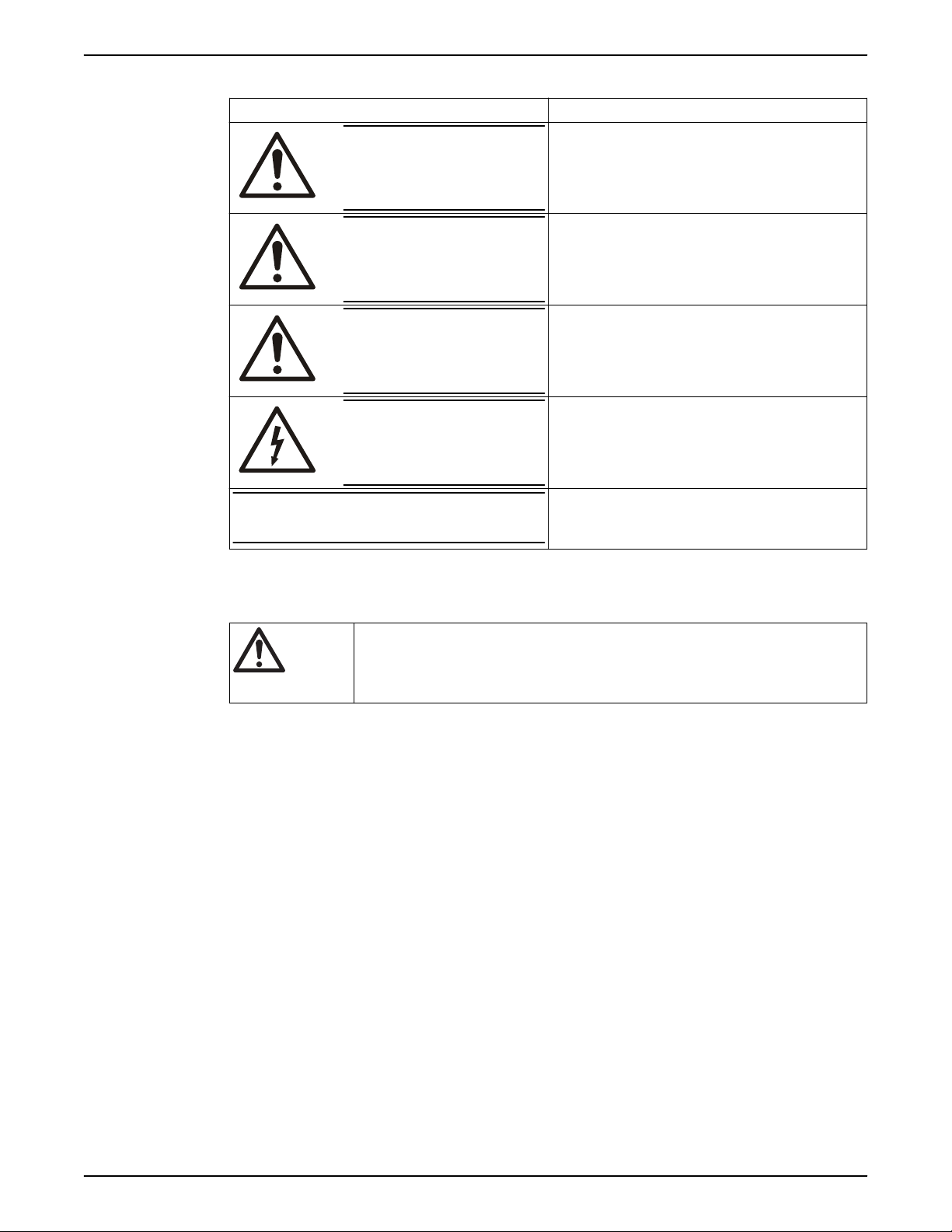
Safety message level Indication
DANGER:
A hazardous situation which, if not avoided, will result in
death or serious injury
NOTICE:
Safety instruction decals
Alert symbol
WARNING:
CAUTION:
Electrical Hazard:
This safety alert symbol is used in manuals and on the safety instruction decals on the pump
to draw attention to safety-related instructions.
When used, the safety alert symbol means that failure to follow the instructions may result in
a safety hazard.
A hazardous situation which, if not avoided, could result
in death or serious injury
A hazardous situation which, if not avoided, could result
in minor or moderate injury
The possibility of electrical risks if instructions are not
followed in a proper manner
• A potential situation which, if not avoided, could
result in undesirable conditions
• A practice not related to personal injury
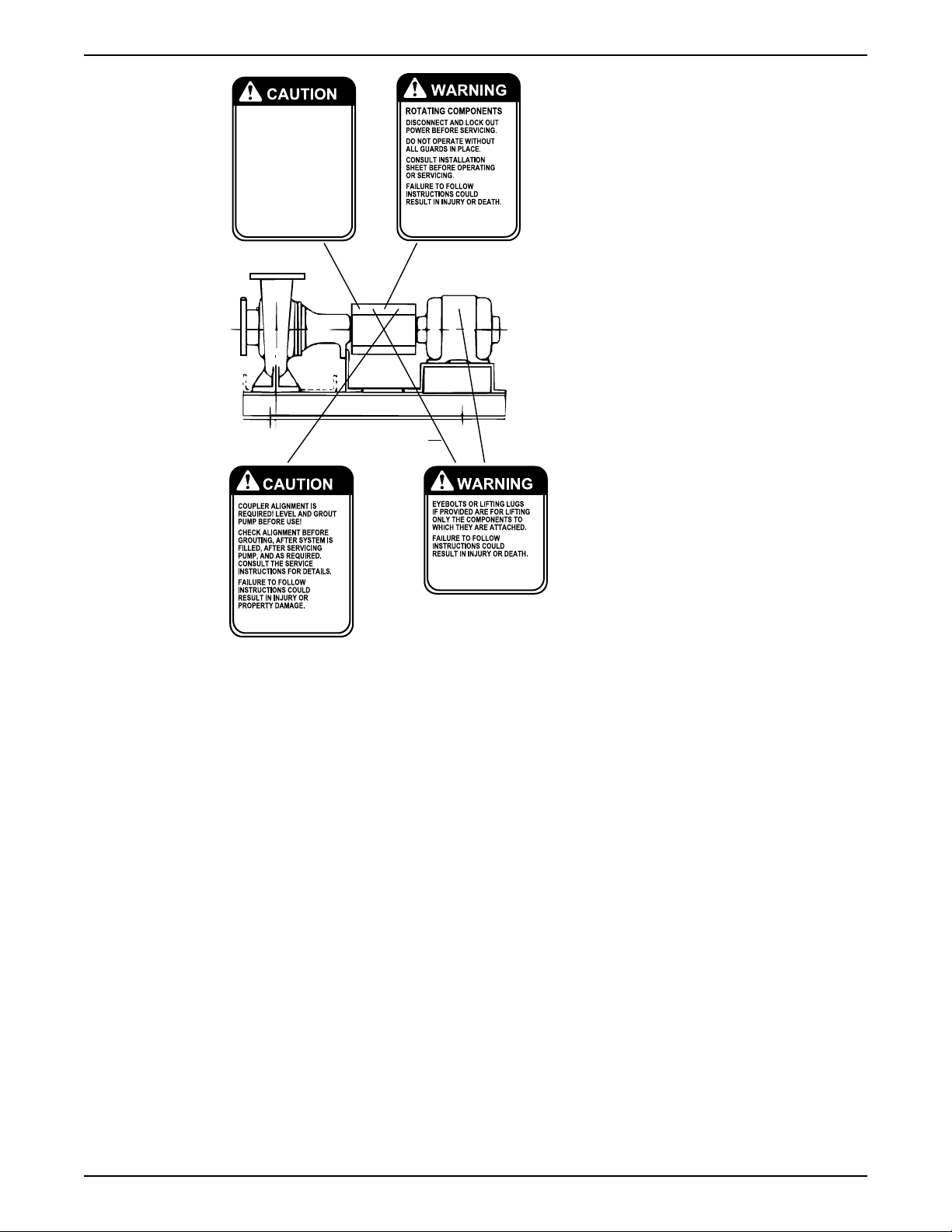
Decals
Make sure your pump has these safety instruction decals and that they are located as this
figure shows. If the decals are missing or illegible, contact your local sales and service
representative for a replacement.
4 Series 1510 Installation, Operation, and Maintenance Manual
P70642
P70643
(2) Required
(1 Each Side)
Alternate
Location
P2002458
P70820
DO NOT RUN PUMP DRY, SEAL
DAMAGE MAY OCCUR.
INSPECT PUMP SEAL
REGULARLY FOR LEAKS,
REPLACE AS REQUIRED.
LUBRICATION REQUIREMENTS
CONSULT MANUALS.
PUMP: POLYUREA-BASED GREASE
FAILURE TO FOLLOW
INSTRUCTIONS COULD
RESULT IN INJURY OR
PROPERTY DAMAGE.
Introduction and Safety
User safety
General safety rules
Safety equipment
Make sure that all safety instruction decals are always clearly visible and readable.
These safety rules apply:
• Always keep the work area clean.
• Pay attention to the risks presented by gas and vapors in the work area.
• Avoid all electrical dangers. Pay attention to the risks of electric shock or arc
hazards.
• Always bear in mind the risk of drowning, electrical accidents, and burn injuries.
Use safety equipment according to the company regulations. Use this safety equipment
within the work area:
• Hard hat
• Safety goggles, preferably with side shields
• Protective shoes
• Protective gloves
• Gas mask
• Hearing protection
• First-aid kit
• Safety devices
flash
Series 1510 Installation, Operation, and Maintenance Manual 5

Introduction and Safety
Electrical connections
Electrical connections must be made by certified electricians in compliance with all
international, national, state, and local regulations. For more information about
requirements, see sections dealing specifically with electrical connections.
Precautions before work
Observe these safety precautions before you work with the product or are in connection
with the product:
• Provide a suitable barrier around the work area, for example, a guard rail.
• Make sure that all safety guards are in place and secure.
• Make sure that you have a clear path of retreat.
• Make sure that the product cannot roll or fall over and injure people or damage
• Make sure that the lifting equipment is in good condition.
• Use a lifting harness, a safety line, and a breathing device as required.
• Allow all system and pump components to cool before you handle them.
• Make sure that the product has been thoroughly cleaned.
• Disconnect and lock out power before you service the pump.
• Check the explosion risk before you weld or use electric hand tools.
NOTICE:
Never operate a unit unless safety devices are installed. Also see specific information
about safety devices in other chapters of this manual.
property.
Precautions during work
Observe these safety precautions when you work with the product or are in connection
with the product:
• Never work alone.
• Always wear protective clothing and hand protection.
• Stay clear of suspended loads.
• Always lift the product by its lifting device.
• Beware of the risk of a sudden start if the product is used with an automatic level
• Beware of the starting jerk, which can be powerful.
• Rinse the components in water after you disassemble the pump.
• Do not exceed the maximum working pressure of the pump.
• Do not open any vent or drain valve or remove any plugs while the system is
• Never operate a pump without a properly installed coupling guard.
Wash the skin and eyes
control.
pressurized. Make sure that the pump is isolated from the system and that pressure is
relieved before you disassemble the pump, remove plugs, or disconnect piping.
Follow these procedures for chemicals or hazardous fluids that have come into
contact with your eyes or your skin:
Condition Action
Chemicals or hazardous fluids in
eyes
1. Hold your eyelids apart forcibly with your fingers.
2. Rinse the eyes with eyewash or running water for at least 15 minutes.
3. Seek medical attention.
6 Series 1510 Installation, Operation, and Maintenance Manual
Condition Action
Chemicals or hazardous fluids on
skin
Environmental safety
The work area
Always keep the station clean.
Waste and emissions regulations
Observe these safety regulations regarding waste and emissions:
• Appropriately dispose of all waste.
• Handle and dispose of the processed liquid in compliance with applicable
environmental regulations.
• Clean up all spills in accordance with safety and environmental procedures.
• Report all environmental emissions to the appropriate authorities.
CAUTION: Radiation Hazard
Do NOT send the product to Xylem if it has been exposed to nuclear radiation, unless
Xylem has been informed and appropriate actions have been agreed upon.
Introduction and Safety
1. Remove contaminated clothing.
2. Wash the skin with soap and water for at least 1 minute.
3. Seek medical attention, if necessary.
Electrical installation
Recycling guidelines
For electrical installation recycling requirements, consult your local electric utility.
Always follow local laws and regulations regarding recycling.
Series 1510 Installation, Operation, and Maintenance Manual 7
Transportation and Storage
Transportation and Storage
Inspect the delivery
Inspect the package
1. Inspect the package for damaged or missing items upon delivery.
2. Note any damaged or missing items on the receipt and freight bill.
3. File a claim with the shipping company if anything is out of order.
If the product has been picked up at a distributor, make a claim directly to the
distributor.
Inspect the unit
1. Remove packing materials from the product.
Dispose of all packing materials in accordance with local regulations.
2. Inspect the product to determine if any parts have been damaged or are missing.
3. If applicable, unfasten the product by removing any screws, bolts, or straps.
For your personal safety, be careful when you handle nails and straps.
4. Contact the local sales representative if there is any issue.
Lifting methods
WARNING:
• Assembled units and their components are heavy. Failure to properly lift and support
• Crush hazard. The unit and the components can be heavy. Use proper lifting methods
• Do not attach sling ropes to shaft ends.
Table 1: Methods
Pump type Lifting method
A bare pump without lifting
handles
A base-mounted pump. Use slings under the pump casing and the drive unit, under the base rails, or
this equipment can result in serious physical injury and/or equipment damage. Lift
equipment only at the specifically identified lifting points. Lifting devices such as
eyebolts, slings, and spreaders must be rated, selected, and used for the entire load
being lifted.
and wear steel-toed shoes at all times.
Use a suitable sling attached properly to solid points like the casing, the flanges, or
the frames.
through lifting lugs, when provided.
8 Series 1510 Installation, Operation, and Maintenance Manual
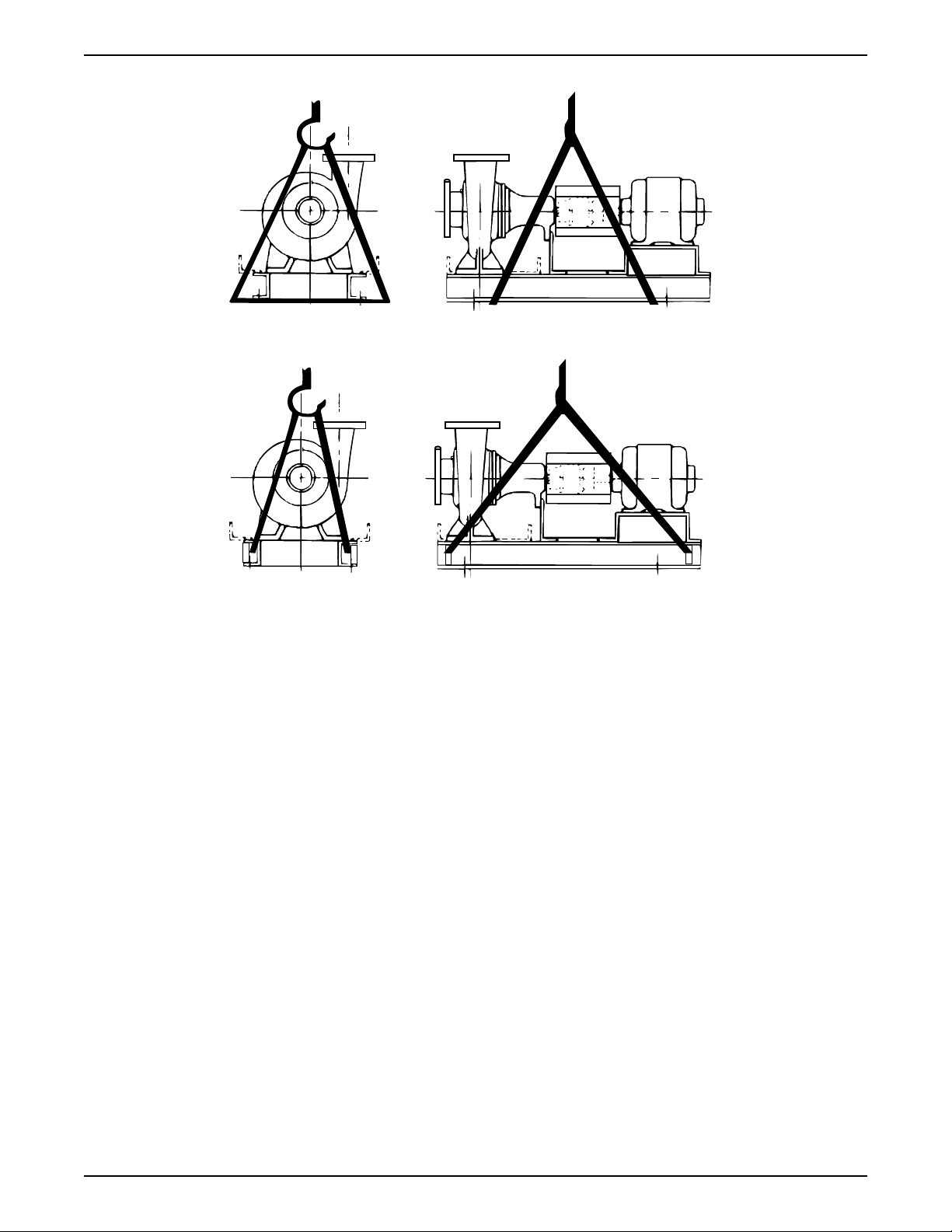
Examples
Transportation and Storage
Figure 1: Example of a proper lifting method
Figure 2: Example of a proper lifting method using lifting lugs
Storage requirements
If the unit will not to be installed and put into operation immediately upon arrival at the
site, or for an extended shutdown after the unit is in operation, the following requirements
for short-term storage apply:
• Store in a covered and dry location.
• Store the unit free from excessive cold or heat (below 32°F and above 110°F), dirt,
and vibration.
• Rotate the shaft by hand several times (10–15 turns) at least every 30 days.
For initial storage longer than three months, or for pump shut down after being in
operation longer than three months, contact your local sales and service representative
for long-term storage guidelines.
Series 1510 Installation, Operation, and Maintenance Manual 9
Product Description
Product Description
General description
Description
The pump is a centrifugal, frame-mounted pump. The following pump features make it
easy to install, operate, and service:
• High efficiency
• Rugged bronze-fitted construction
• Foot-mounted volute with back pullout bearing frame
• Center drop-out coupler
• Regreasable bearings
Intended applications
WARNING:
California Proposition 65 warning! This product contains chemicals known to the state of
California to cause cancer and birth defects or other reproductive harm.
The pump is intended for use with these pumped fluids:
• Unheated domestic and fresh water
• Boiler feed water
• Condensate
• Hydronic cooling or heating
• Benign liquids
• Pressure boosting
• General liquid transfer
Rotation
Pump rotation is clockwise when viewed from the back of the motor. An arrow is also
located on the pump to show the direction of rotation.
Operational
Mechanical seal specifications
specifications
This table describes the specifications of each mechanical seal type.
Seal type Parameter Value
Standard seals, BUNA pH range limits for BUNA pH 7–9
Standard seals, EPT pH range limits for EPT pH 7–11
Flushed single seals
Flushed double seals
1,3,4
1,3,4
Liquid temperature range that
complies with the pH range limits for
BUNA
Liquid temperature range that
complies with the pH range limits for
EPT
pH range limits pH 7–9
Liquid temperature range 0˚F to 250˚F (-18˚C to 121˚C)
pH range limits pH 7–9
Liquid temperature range 0˚F to 250˚F (-18˚C to 121˚C)
-20˚F to 225˚F (-29˚C to 107˚C)
-20˚F to 250˚F (-29˚C to 121˚C)
10 Series 1510 Installation, Operation, and Maintenance Manual

Product Description
Seal type Parameter Value
2
Packing
pH range pH 7–9
Liquid temperature range 0˚F to 200˚F (-18˚C to 93˚C)
Table notes
1. An external flush is required on low pressure systems that contain a high
concentration of abrasives.
2. Use packing on open or closed systems which require a large amount of makeup
water, as well as systems that are subjected to a wide variety of chemical conditions
and solids buildup.
3. For operating temperatures above 250°F, a cooled flush is required and is
recommended for temperatures above 225°F for optimum seal life. On closed
systems, cooling is accomplished by inserting a small heat exchanger in the flush line
to cool the seal flushing fluid.
4. Flush-line filters and sediment separators are available on request.
Series 1510 Installation, Operation, and Maintenance Manual 11
Installation
Installation
Preinstallation
Precautions
WARNING:
• When installing in a potentially explosive environment, make sure that the motor is
properly certified.
• You must ground (earth) all electrical equipment. This applies to the pump
equipment, the driver, and any monitoring equipment. Test the ground (earth) lead to
verify that it is connected correctly.
NOTICE:
Supervision by an authorized Xylem representative is recommended to ensure proper
installation. Failure to do so may result in equipment damage or decreased performance.
Evaluate the installation in order to determine that the Net Positive Suction Head Available
(NPSHA) meets or exceeds the Net Positive Suction Head Required (NPSHR), as stated by
the pump performance curve.
Pump location guidelines
WARNING:
Assembled units and their components are heavy. Failure to properly lift and support this
equipment can result in serious physical injury and/or equipment damage. Lift equipment
only at the specifically identified lifting points. Lifting devices such as eyebolts, slings, and
spreaders must be rated, selected, and used for the entire load being lifted.
Guideline Explanation/comment
Keep the pump as close to the liquid source as
practically possible.
Make sure that the space around the pump is
sufficient.
If you require lifting equipment such as a hoist or
tackle, make sure that there is enough space above
the pump.
Protect the unit from weather and water damage due
to rain, flooding, and freezing temperatures.
Do not install and operate the equipment in closed
systems unless the system is constructed with
properly-sized safety devices and control devices.
Take into consideration the occurrence of unwanted
noise and vibration.
If the pump location is overhead, undertake special
precautions to reduce possible noise transmission.
This minimizes the friction loss and keeps the suction piping
as short as possible.
This facilitates ventilation, inspection, maintenance, and
service.
This makes it easier to properly use the lifting equipment and
safely remove and relocate the components to a safe location.
This is applicable if nothing else is specified.
Acceptable devices:
• Pressure relief valves
• Compression tanks
• Pressure controls
• Temperature controls
• Flow controls
If the system does not include these devices, consult the
engineer or architect in charge before you operate the pump.
The best pump location for noise and vibration absorption is
on a concrete floor with subsoil underneath.
Consider a consultation with a noise specialist.
12 Series 1510 Installation, Operation, and Maintenance Manual
 Loading...