

Bell & Gossett P81630F User Manual
INSTRUCTION MANUAL
P81630
REVISION F
INSTALLER: PLEASE LEAVE THIS MANUAL FOR THE OWNER’S USE.
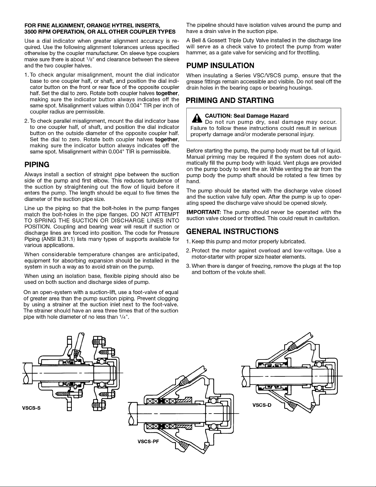
Series VSC® and VSCS®
Base Mounted
Centrifugal Pumps
(TO BE USED IN CONJUNCTION WITH VSC PARTS LIST CONTAINING LINE DRAWINGS)
2
ADDITIONAL SAFETY REQUIREMENTS:
ELECTRICAL SAFETY:
MECHANICAL SAFETY:
WARNING: Electrical Shock Hazard
Electrical connections to be made by a qualified
electrician in accordance with all applicable codes, ordinances, and good practices. Failure to follow these instructions could result in serious personal injury or death,
or property damage.
WARNING: Electrical Overload Hazard
Three phase motors must have properly sized
heaters to provide overload and undervoltage protection.
Single phase motors have built-in overload protectors.
Failure to follow these instructions could result in serious
personal injury or death, or property damage.
THERMAL SAFETY:
WARNING: Extreme Temperature Hazard
If pump, motor, or piping are operating at extremely
high or low temperatures, guarding or insulation is required. Failure to follow these instructions could result in
serious personal injury or death, or pr
operty damage.
PUMP LOCATION
Locate the pump so there is sufficient room for inspection, maintenance and service. If the use of a hoist or tackle is needed,
allow ample head room.
WARNING: Unexpected Startup Hazard
Disconnect and lockout power before servicing.
Failure to follow these instructions could result in serious
personal injury or death, or property damage.
W
ARNING: Excessive System Pressure Hazard
The maximum working pressure of the pump is listed
on the nameplate, do not exceed this pressure. Failure to
follow these instructions could r
esult in serious personal
injury or death, or property damage.
WARNING: Excessive Pr
essure Hazard
Volumetric Expansion
The heating of water and other fluids causes volumetric
expansion. The associated forces may cause failur
e of system components and release of high temperature fluids.
This will be prevented by installing properly sized and
located compression tanks and pressure relief valves.
Failure to follow these instructions could result in serious
personal injury or death, or property damage.
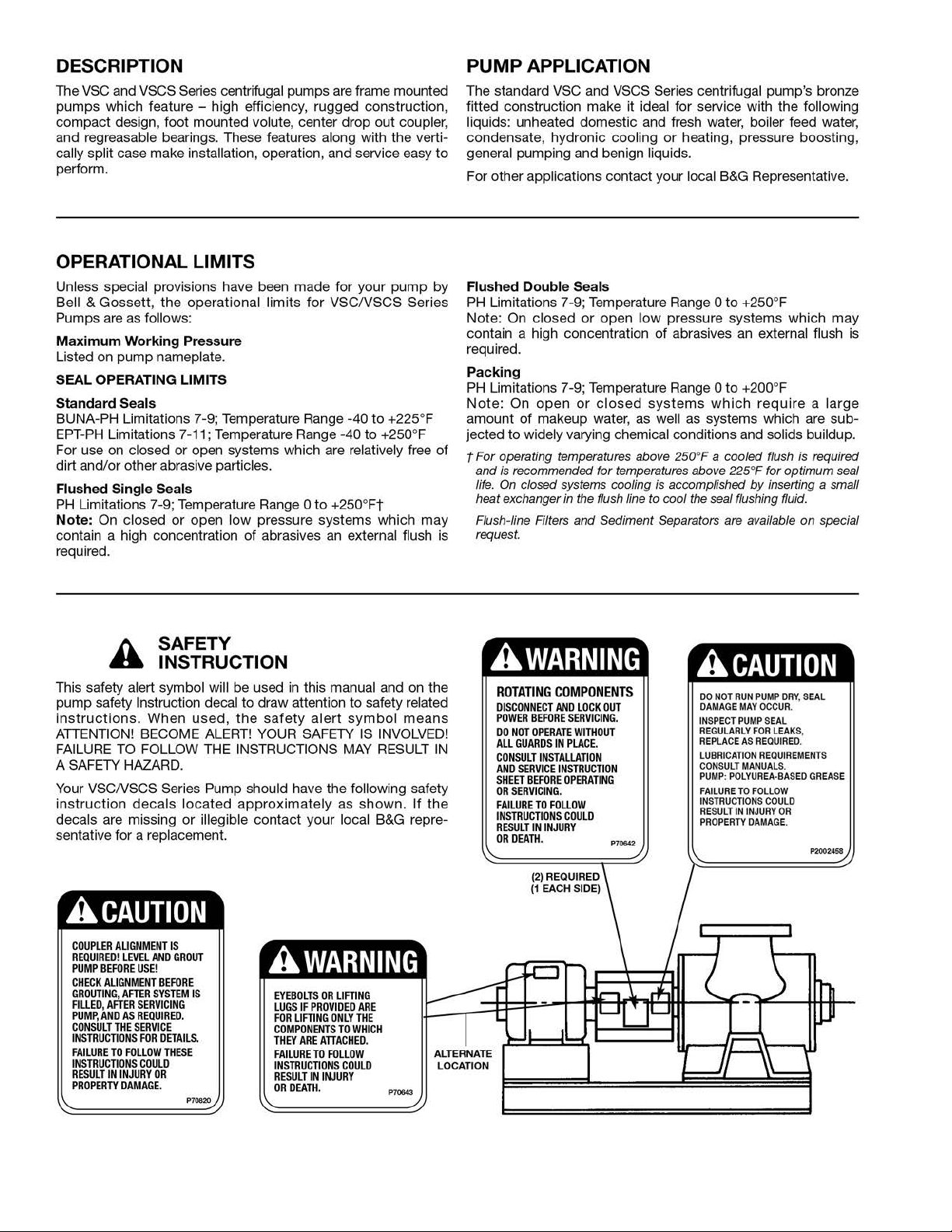
WARNING: Fall Objects Hazard
Eyebolts or lifting lugs, if provided, are for lifting only
the components to which they are attached. Failure to follow these instructions could result in serious personal
injury or death, or property damage.
If lifting of the entire pump is required, do so with slings placed
under the base rails as shown.
The best pump location for sound and vibration absorption is
on a concrete floor with subsoil underneath. If the pump location is overhead, special precautions should be undertaken to
reduce possible sound transmission, consult a sound specialist.
If the pump is not on a closed system, it should be placed as
near as possible to the source of the liquid supply, and located
to permit installation with the fewest number of bends or
elbows in the suction pipe.
COMPRESSION TANK
SHOULD BE LOCATED
ON THE SUCTION SIDE
OF THE PUMP
B&G REDUCING
VALVE
COLD
WATER
SUPPLY
FROM BOILER
CHILLER OR CONVER
TER
B&G ROLAIRTROL
AIR SEPARATOR
ISOLATION
VALVE
SUPPLY
TO SYSTEM
B&G CIRCUIT
SETTER
B&G TRIPLE DUTY
VALVE
The installation must be evaluated to determine that the Net
Positive Suction Head Available (NPSHA) meets or exceeds the
Net Positive Suction Head Required (NPSHR), as stated by the
pump performance curve.
IMPORTANT
Do not install and operate Bell & Gossett Pumps, 3D Valves,
Suction Diffusers, etc., in closed systems unless the system is
constructed with properly sized safety devices and control
devices. Such devices include the use of properly sized and
located pressure relief valves, compression tanks, pressure controls, temperature controls, and flow controls as appropriate. If
the system does not include these devices, consult the responsible engineer or architect before making pumps operational.
3
INSTALLATION
This pump is built to provide years of service if installed properly
and attached to a suitable foundation. A base of concrete weighing 21/2 times the weight of the pump is r
the shipping ticket for pump weight.)
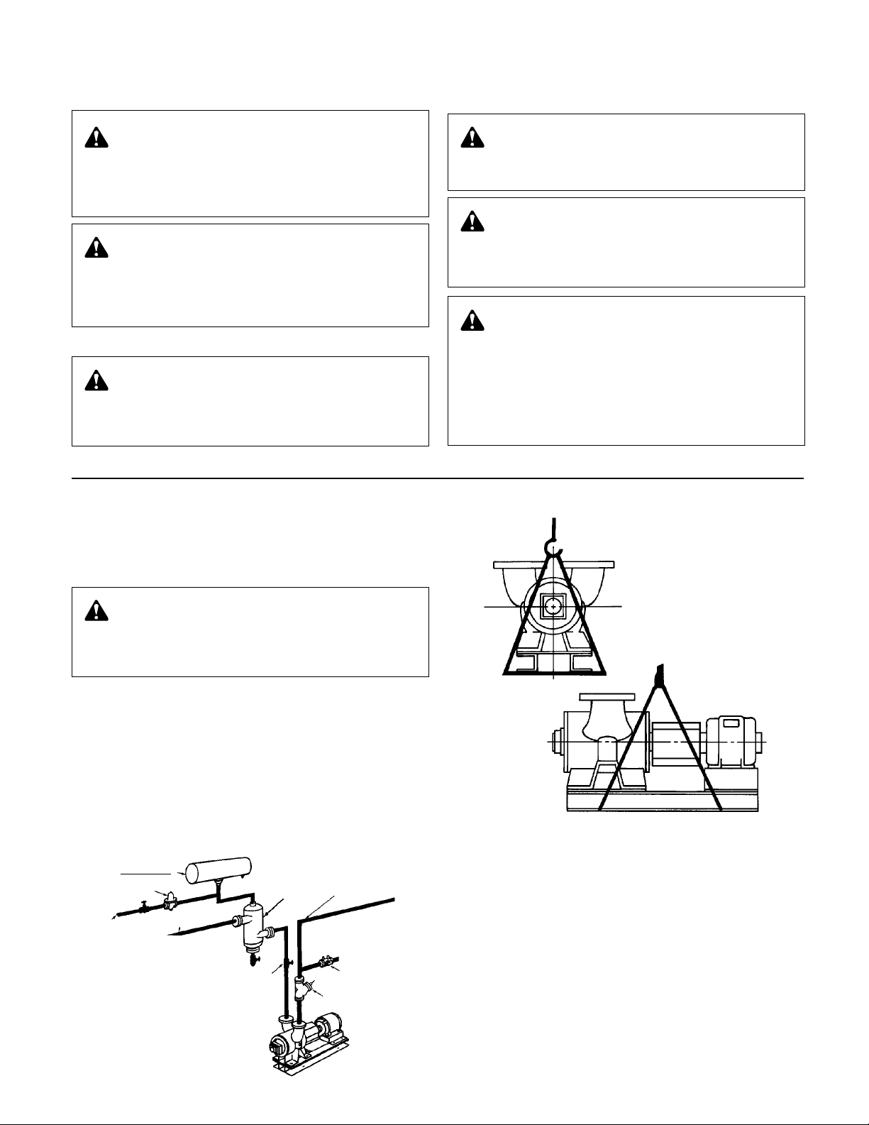
If possible, tie the concrete pad in with the finished floor. Use
foundation bolts and larger pipe-sleeves to give room for final
bolt location. (See Figure 6A.)
ecommended. (Check
PIPE
SLEEVE
FOUNDATION
BOLT
LEVELING
Place the pump on its concrete foundation supporting it with
steel wedges or shims totaling 1" in thickness. These wedges
or shims should be put on both sides of each anchor-bolt to
provide a means of leveling the base. (See Figure 6B.)
It is very important that the pump-base be set level to avoid any
mechanical difficulties with the motor or pump. This pump was
properly aligned (if furnished with a motor) at the factory
. However, since all pump bases are flexible they may spring and twist
during shipment. Don’t pipe the pump until it is realigned. After
piping is completed and after the pump is grouted-in and bolteddown, align it again. It may be necessary to re-adjust the alignment from time to time while the unit and foundation are new.
GROUTING
After the pump has been leveled, securely bolted to the floor,
and properly aligned, a good grade of non-shrinking grout
should be poured inside the pump base. To hold wedges or
shims in place, allow the grout to flow around them.
ROTATION
The VSC & VSCS pump is available in both right- and left-hand
rotation. An arrow cast into the pump body shows the direction
of rotation.
BUILT-UP
CONCRETE FOUNDATION
ALLOW 1" FOR SHIMS.
PLACE ON BOTH SIDES
OF ANCHOR BOLTS.
APPROX.
GAP
1"
LEVELING OF PUMP BASE
ON CONCRETE FOUNDATION.
WASHER
NOTE:
TO KEEP SHIMS IN
PLACE ALLOW GROUT
TO FLOW AROUND
HOLD DOWN LUGS.
GROUT
CONCRETE
FOUNDATION
FIGURE 6A
GROUT ONLY TO
TOP OF BASE RAIL.
PUMP
BASE RAIL
FIGURE 6B
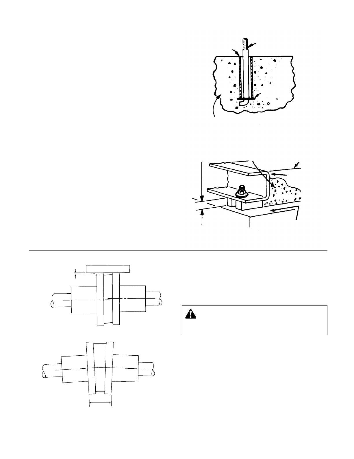
AMOUNT OF
PARALLEL
MISALIGNMENT
STRAIGHT EDGE
PARALLEL ALIGNMENT CHECK
DISTANCES ACROSS
COUPLER FLANGES
SHOULD BE EQUAL
(CHECK 4 PLACES)
ANGULAR ALIGNMENT CHECK
COUPLER ALIGNMENT
All alignment should be done by moving or shimming the motor
only. Adjustments in one direction may alter alignment in another.
Therefore, check alignment in all directions after a correction is
made. Black rubber inserts have different horsepower load
ratings than orange Hytrel sleeves. They should not be
interchanged.
WARNING: Unexpected Startup Hazard
Disconnect and lockout power before servicing.
Failure to follow these instructions could result in serious
personal injury or death, or property damage.
STANDARD SLEEVE TYPE COUPLER
WITH BLACK RUBBER INSERT
Before aligning the coupler, make sure there is about 1/8" end
clearance between the sleeve and the two coupler halves.
1. Check angular misalignment using a micrometer or caliper.
Measure from the outside of one flange to the outside of the
opposite flange at four points 90° apart. DO NOT ROTATE
COUPLER. Misalignment up to 1/64" per inch of coupler
radius is permissible.
2. At four points 90° apart (DO NOT ROTATE COUPLER), measure the parallel coupler misalignment by laying a straight
edge across one coupler half and measuring the gap
between the straight edge and opposite coupler half. Up to a
1
/64" gap is permissible.
4
5
 Loading...