

Page 1
Installation,
Operation, and
Maintenance Manual
Series 1531
Page 2

Page 3

Table of Contents
Introduction and Safety.........................................................................................................................2
Introduction..........................................................................................................................................2
Requesting other information.........................................................................................................2
Safety.....................................................................................................................................................2
Safety terminology and symbols....................................................................................................3
Safety instruction decals..................................................................................................................4
User safety.........................................................................................................................................4
Environmental safety........................................................................................................................6
Product warranty.................................................................................................................................6
Transportation and Storage..................................................................................................................8
Inspect the delivery.............................................................................................................................8
Inspect the package.........................................................................................................................8
Inspect the unit..................................................................................................................................8
Pump lifting..........................................................................................................................................8
Long-term storage...............................................................................................................................9
Product Description.............................................................................................................................10
General description..........................................................................................................................10
Operational specifications...............................................................................................................10
Table of Contents
Installation.............................................................................................................................................12
Preinstallation....................................................................................................................................12
Pump location guidelines..............................................................................................................12
Foundation requirements.............................................................................................................13
Piping checklist...............................................................................................................................14
Typical installation.............................................................................................................................15
Commissioning, Startup, Operation, and Shutdown......................................................................16
Preparation for startup.....................................................................................................................16
Prime the pump.................................................................................................................................16
Start the pump...................................................................................................................................17
Pump operation precautions...........................................................................................................17
Shut down the pump........................................................................................................................18
Note on the packed pump operation.............................................................................................18
Maintenance.........................................................................................................................................20
Bearing maintenance........................................................................................................................20
Disassembly.......................................................................................................................................20
Disassembly precautions...............................................................................................................20
Drain the pump...............................................................................................................................20
Remove the bearing frame and impeller assembly...................................................................21
Remove the mechanical seal (1531 and 1531-F) ......................................................................21
Remove the seal or packing rings (1531-S, 1531-D, and 1531-PF) ........................................21
Pre-assembly inspections.................................................................................................................21
Shaft and sleeve inspection..........................................................................................................21
Reassembly........................................................................................................................................22
Seal assembly..................................................................................................................................22
Assemble the packed stuffing box (1531-PF) ............................................................................24
Reinstall the bearing frame and impeller assembly ..................................................................25
Capscrew torque values................................................................................................................25
Dealer servicing .............................................................................................................................26
Series 1531 Installation, Operation, and Maintenance Manual 1
Page 4
Introduction and Safety
Introduction and Safety
Introduction
Purpose of this manual
The purpose of this manual is to provide necessary information for:
• Installation
• Operation
• Maintenance
CAUTION:
Read this manual carefully before installing and using the product. Improper use of the
product can cause personal injury and damage to property, and may void the warranty.
NOTICE:
Save this manual for future reference, and keep it readily available at the location of the
unit.
Requesting other information
Special versions can be supplied with supplementary instruction leaflets. See the sales
contract for any modifications or special version characteristics. For instructions, situations,
or events that are not considered in this manual or in the sales documents, please contact
the nearest Xylem representative.
Always specify the exact product type and identification code when requesting technical
information or spare parts.
Safety
WARNING:
• The operator must be aware of safety precautions to prevent physical injury.
• Any pressure-containing device can explode, rupture, or discharge its contents if it is
over-pressurized. Take all necessary measures to avoid over-pressurization.
• Operating, installing, or maintaining the unit in any way that is not covered in this manual
could cause death, serious personal injury, or damage to the equipment. This includes
any modification to the equipment or use of parts not provided by Xylem. If there is a
question regarding the intended use of the equipment, please contact a Xylem
representative before proceeding.
• Do not change the service application without the approval of an authorized Xylem
representative.
CAUTION:
You must observe the instructions contained in this manual. Failure to do so could result in
physical injury, damage, or delays.
2 Series 1531 Installation, Operation, and Maintenance Manual
Page 5
Safety terminology and symbols
About safety messages
It is extremely important that you read, understand, and follow the safety messages and
regulations carefully before handling the product. They are published to help prevent
these hazards:
• Personal accidents and health problems
• Damage to the product
• Product malfunction
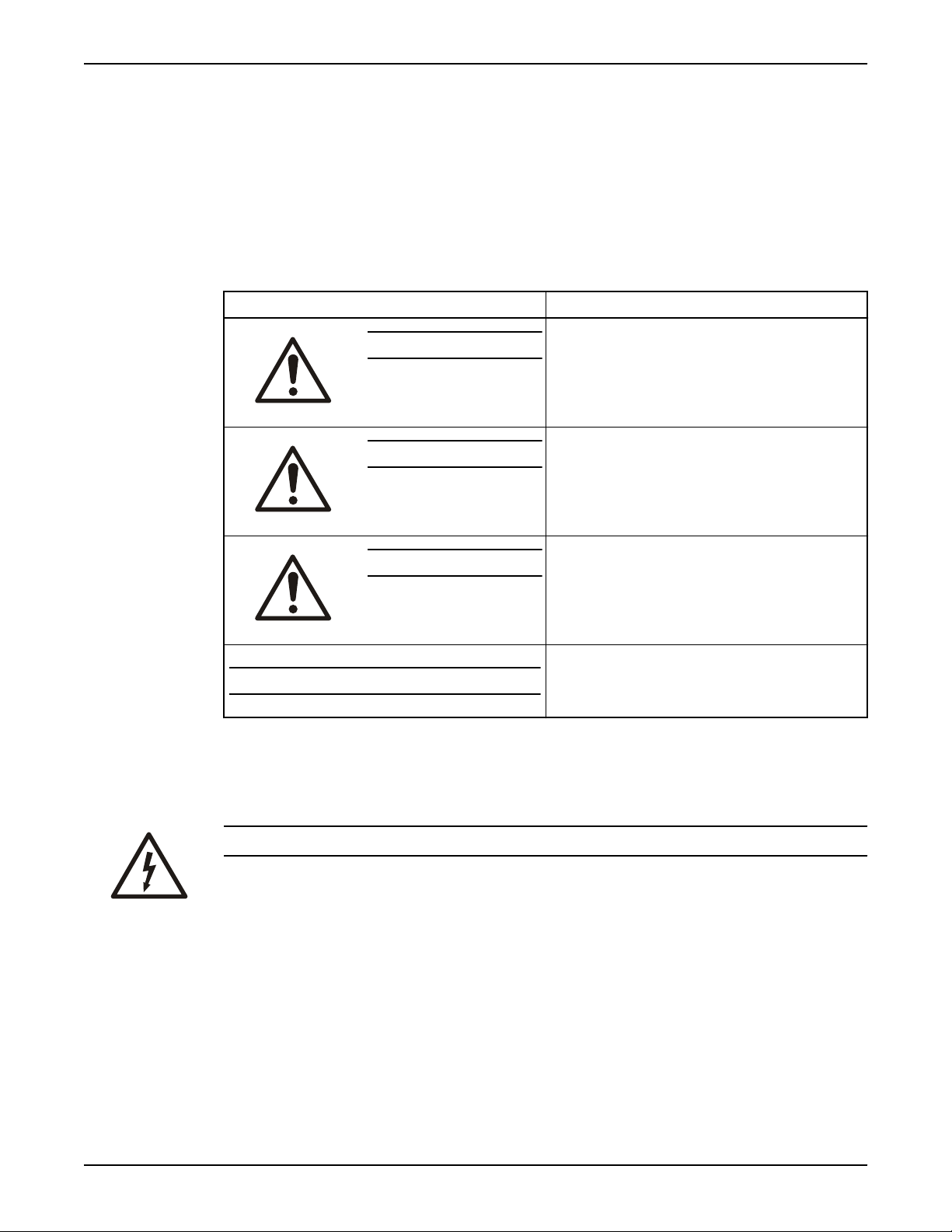
Hazard levels
Hazard level Indication
Introduction and Safety
Hazard categories
DANGER:
WARNING:
CAUTION:
NOTICE:
Hazard categories can either fall under hazard levels or let specific symbols replace the
ordinary hazard level symbols.
Electrical hazards are indicated by the following specific symbol:
A hazardous situation which, if not avoided, will result in
death or serious injury
A hazardous situation which, if not avoided, could result
in death or serious injury
A hazardous situation which, if not avoided, could result
in minor or moderate injury
• A potential situation which, if not avoided, could
result in undesirable conditions
• A practice not related to personal injury
Electrical Hazard:
These are examples of other categories that can occur. They fall under the ordinary hazard
levels and may use complementing symbols:
• Crush hazard
• Cutting hazard
• Arc flash hazard
Series 1531 Installation, Operation, and Maintenance Manual 3
Page 6
Introduction and Safety
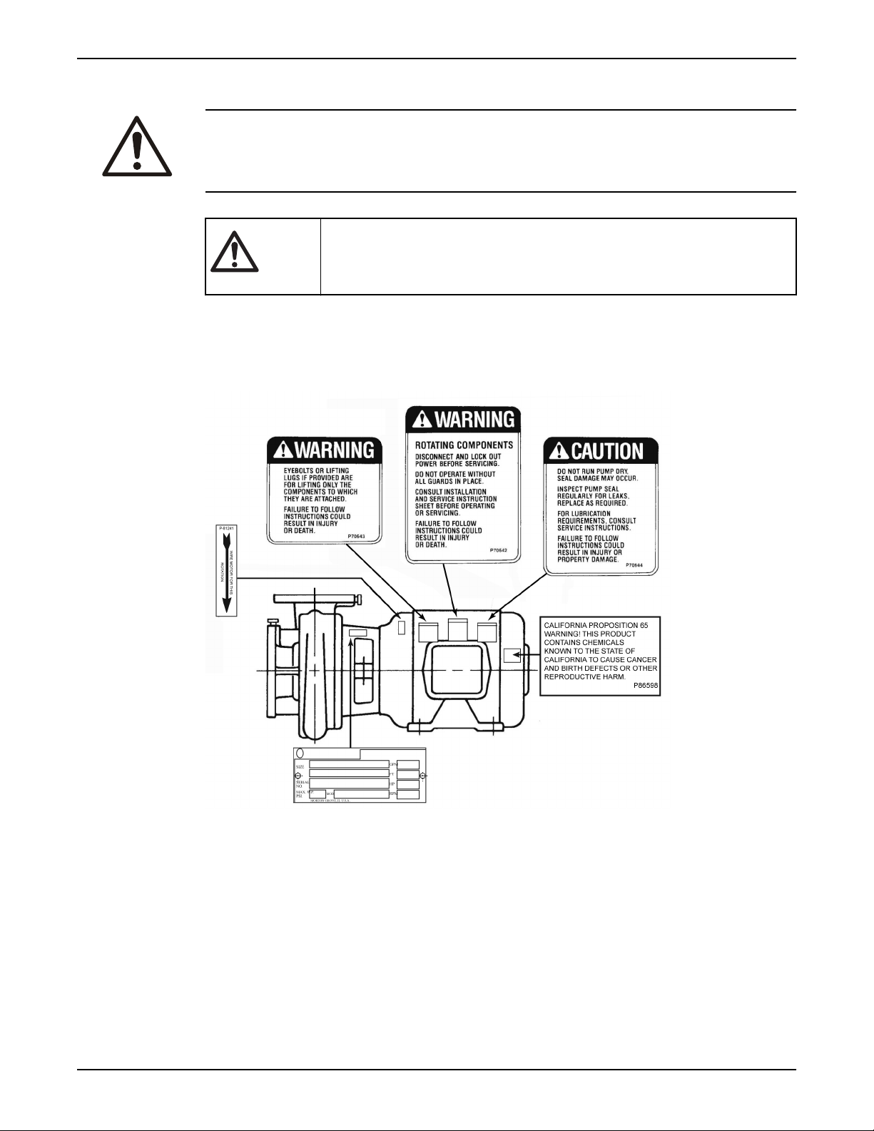
Safety instruction decals
WARNING:
The maximum working pressure of the pump is listed on the nameplate. Do not exceed
this pressure. Failure to follow these instructions can result in serious personal injury,
death, and/or property damage.
Alert symbol
Decals
Make sure your pump has these safety instruction decals and that they are located as this
figure shows. If the decals are missing or illegible, contact your local sales and service
representative for a replacement.
This safety alert symbol is used in manuals and on the safety instruction decals on the pump
to draw attention to safety-related instructions.
When used, the safety alert symbol means that failure to follow the instructions may result in
a safety hazard.
Make sure that all safety instruction decals are always clearly visible and readable.
User safety
General safety rules
These safety rules apply:
• Always keep the work area clean.
• Pay attention to the risks presented by gas and vapors in the work area.
• Avoid all electrical dangers. Pay attention to the risks of electric shock or arc flash
hazards.
• Always bear in mind the risk of drowning, electrical accidents, and burn injuries.
4 Series 1531 Installation, Operation, and Maintenance Manual
Page 7
Safety equipment
Use safety equipment according to the company regulations. Use this safety equipment
within the work area:
Electrical connections
Electrical connections must be made by certified electricians in compliance with all
international, national, state, and local regulations. For more information about
requirements, see sections dealing specifically with electrical connections.
Introduction and Safety
• Hard hat
• Safety goggles, preferably with side shields
• Protective shoes
• Protective gloves
• Gas mask
• Hearing protection
• First-aid kit
• Safety devices
NOTICE:
Never operate a unit unless safety devices are installed. Also see specific information
about safety devices in other chapters of this manual.
Precautions before work
Observe these safety precautions before you work with the product or are in connection
with the product:
• Provide a suitable barrier around the work area, for example, a guard rail.
• Make sure that all safety guards are in place and secure.
• Make sure that you have a clear path of retreat.
• Make sure that the product cannot roll or fall over and injure people or damage
• Make sure that the lifting equipment is in good condition.
• Use a lifting harness, a safety line, and a breathing device as required.
• Allow all system and pump components to cool before you handle them.
• Make sure that the product has been thoroughly cleaned.
• Disconnect and lock out power before you service the pump.
• Check the explosion risk before you weld or use electric hand tools.
Wash the skin and eyes
property.
Follow these procedures for chemicals or hazardous fluids that have come into contact
with your eyes or your skin:
Condition Action
Chemicals or hazardous
fluids in eyes
1. Hold your eyelids apart forcibly with your fingers.
2. Rinse the eyes with eyewash or running water for at least 15 minutes.
3. Seek medical attention.
Chemicals or hazardous
fluids on skin
1. Remove contaminated clothing.
2. Wash the skin with soap and water for at least 1 minute.
3. Seek medical attention, if necessary.
Series 1531 Installation, Operation, and Maintenance Manual 5
Page 8

Introduction and Safety
Environmental safety
The work area
Always keep the station clean.
Waste and emissions regulations
Observe these safety regulations regarding waste and emissions:
• Appropriately dispose of all waste.
• Handle and dispose of the processed liquid in compliance with applicable
environmental regulations.
• Clean up all spills in accordance with safety and environmental procedures.
• Report all environmental emissions to the appropriate authorities.
WARNING:
Radiation Hazard. Do NOT send the product to Xylem if it has been exposed to any nuclear
radiation.
Electrical installation
For electrical installation recycling requirements, consult your local electric utility.
Recycling guidelines
Always follow local laws and regulations regarding recycling.
Product warranty
Coverage
Xylem undertakes to remedy defects in products from Xylem under these conditions:
• The faults are due to defects in design, materials, or workmanship.
• The faults are reported to an local sales and service representative within the warranty
period.
• The product is used only under the conditions described in this manual.
• The monitoring equipment incorporated in the product is correctly connected and in
use.
• All service and repair work is done by Xylem authorized personnel.
• Genuine Xylem parts are used.
• Only Ex-approved spare parts and accessories authorized by an EX-approved Xylem
representative are used in Ex-approved products.
Limitations
The warranty does not cover defects caused by these situations:
• Deficient maintenance
• Improper installation
• Modifications or changes to the product and installation made without consulting an
Xylem authorized representative
• Incorrectly executed repair work
• Normal wear and tear
Xylem assumes no liability for these situations:
• Bodily injuries
• Material damages
• Economic losses
6 Series 1531 Installation, Operation, and Maintenance Manual
Page 9

Warranty claim
Introduction and Safety
Xylem products are high-quality products with expected reliable operation and long life.
However, should the need arise for a warranty claim, then contact your local sales and
service representative.
Series 1531 Installation, Operation, and Maintenance Manual 7
Page 10

Transportation and Storage
Transportation and Storage
Inspect the delivery
Inspect the package
1. Inspect the package for damaged or missing items upon delivery.
2. Note any damaged or missing items on the receipt and freight bill.
3. File a claim with the shipping company if anything is out of order.
If the product has been picked up at a distributor, make a claim directly to the
distributor.
Inspect the unit
1. Remove packing materials from the product.
Dispose of all packing materials in accordance with local regulations.
2. Inspect the product to determine if any parts have been damaged or are missing.
3. If applicable, unfasten the product by removing any screws, bolts, or straps.
For your personal safety, be careful when you handle nails and straps.
4. Contact the local sales representative if there is any issue.
Pump lifting
WARNING:
• Assembled units and their components are heavy. Failure to properly lift and support
this equipment can result in serious physical injury and/or equipment damage. Lift
equipment only at the specifically identified lifting points. Lifting devices such as
eyebolts, slings, and spreaders must be rated, selected, and used for the entire load
being lifted.
• Crush hazard. The unit and the components can be heavy. Use proper lifting methods
and wear steel-toed shoes at all times.
In order to lift the entire pump, use slings placed around the unit as shown.
Figure 1: Proper lifting method
8 Series 1531 Installation, Operation, and Maintenance Manual
Page 11

Long-term storage
If the unit is stored for more than 6 months, these requirements apply:
• Store in a covered and dry location.
• Store the unit free from heat, dirt, and vibrations.
• Rotate the shaft by hand several times at least every three months.
Treat bearing and machined surfaces so that they are well preserved. Refer to the drive
unit and coupling manufacturers for their long-term storage procedures.
For questions about possible long-term storage treatment services, please contact your
local sales and service representative.
Transportation and Storage
Series 1531 Installation, Operation, and Maintenance Manual 9
Page 12

Product Description
Product Description
General description
The Series 1531 pump is a centrifugal, close-coupled pump. These features make the
pump easy to install, operate, and service:
• High efficiency
• Rugged bronze-fitted construction
• Foot-mounted motor
Intended applications
WARNING:
California Proposition 65 warning! This product contains chemicals known to the state of
California to cause cancer and birth defects or other reproductive harm.
NOTICE:
This product is not intended for potable water applications.
The pump is intended for use with these pumped fluids:
• Unheated domestic and fresh water
• Boiler feed water
• Condensate
• Hydronic cooling or heating
• Benign liquids
• Pressure boosting
• General liquid transfer
Rotation
Pump rotation is clockwise when viewed from the back of the motor. An arrow is also
located on the pump to show the direction of rotation.
Operational specifications
Mechanical seal specifications
This table describes the specifications of each mechanical seal type.
Seal type Parameter Value
Standard seals, BUNA carbon/ceramic pH range limits for BUNA pH 7–9
Liquid temperature range that
complies with the pH range limits for
BUNA
-20˚F to 225˚F (-29˚C to 107˚C)
Optional seals, EPR carbon/tungsten
carbide
EPR/SiC/SiC pH range limits pH 7–12.5
10 Series 1531 Installation, Operation, and Maintenance Manual
pH range limits for EPR pH 7–11
Liquid temperature range that
complies with the pH range limits for
EPR
Liquid temperature range
-20˚F to 250˚F (-29˚C to 121˚C)
-20˚F to 250˚F (-29˚C to 121˚C)
Page 13

Seal type Parameter Value
Flushed single seals
1,3,4
pH range limits pH 7–9
Product Description
0˚F to 250˚F (-18˚C to 121˚C)
0˚F to 200˚F (-18˚C to 93˚C)
Packing
Liquid temperature range
2
pH range pH 7–9
Liquid temperature range
Table notes
1. An external flush is required on low pressure systems that contain a high
concentration of abrasives.
2. Use packing on open or closed systems which require a large amount of makeup
water, as well as systems that are subjected to a wide variety of chemical conditions
and solids buildup.
3. For operating temperatures above 250°F, a cooled flush is required and is
recommended for temperatures above 225°F for optimum seal life. On closed
systems, cooling is accomplished by inserting a small heat exchanger in the flush line
to cool the seal flushing fluid.
4. Flush-line filters and sediment separators are available on request.
5. Use a standard seal on closed or open systems that are relatively free of dirt and/or
other abrasive particles.
Series 1531 Installation, Operation, and Maintenance Manual 11
Page 14

Installation
Installation
Preinstallation
Precautions
WARNING:
• When installing in a potentially explosive environment, make sure that the motor is
properly certified.
• You must earth (ground) all electrical equipment. This applies to the pump equipment,
the driver, and any monitoring equipment. Test the earth (ground) lead to verify that it is
connected correctly.
• Motors without built-in protection must be provided with contactors and thermal
overload protection for single-phase motors, or starters with heaters for three-phase
motors. (See the nameplate on the drive unit to select properly-sized overloads.)
NOTICE: Supervision by an authorized Xylem representative is recommended to ensure
proper installation. Failure to do so may result in equipment damage or decreased
performance.
Evaluate the installation in order to determine that the Net Positive Suction Head Available
(NPSHA) meets or exceeds the Net Positive Suction Head Required (NPSHR), as stated by
the pump performance curve.
Pump location guidelines
WARNING:
Assembled units and their components are heavy. Failure to properly lift and support this
equipment can result in serious physical injury and/or equipment damage. Lift equipment
only at the specifically identified lifting points. Lifting devices such as eyebolts, slings, and
spreaders must be rated, selected, and used for the entire load being lifted.
Guideline Explanation/comment
Keep the pump as close to the liquid source as
practically possible.
If the pump is not on a closed system, locate the pump
so that the fewest number of bends or elbows in the
suction pipe are needed.
Make sure that the space around the pump is sufficient. This facilitates ventilation, inspection, maintenance, and
If you require lifting equipment such as a hoist or tackle,
make sure that there is enough space above the pump.
This minimizes the friction loss and keeps the suction
piping as short as possible.
service.
This makes it easier to properly use the lifting
equipment and safely remove and relocate the
components to a safe location.
Protect the unit from weather and water damage due to
rain, flooding, and freezing temperatures.
Do not install and operate the equipment in closed
systems unless the system is constructed with properlysized safety devices and control devices.
12 Series 1531 Installation, Operation, and Maintenance Manual
This is applicable if nothing else is specified.
Acceptable devices:
• Pressure relief valves
• Compression tanks
• Pressure controls
Page 15

Guideline Explanation/comment
Correct
Incorrect
• Temperature controls
• Flow controls
If the system does not include these devices, consult the
engineer or architect in charge before you operate the
pump.
Installation
Take into consideration the occurrence of unwanted
noise and vibration.
If the pump location is overhead, undertake special
precautions to reduce possible noise transmission.
When possible, locate the pump below the fluid level. This facilitates priming, ensures a steady flow of liquid,
Foundation requirements
Requirements
• The foundation must be able to absorb any type of vibration and form a permanent,
rigid support for the unit.
• The foundation must weigh at least 2-1/2 times the weight of the pump unit.
• Provide a flat, substantial concrete foundation in order to prevent strain and distortion
when you tighten the foundation bolts.
• Sleeve-type and J-type foundation bolts are most commonly used. Both designs allow
movement for the final bolt adjustment.
• Tie the concrete pad in with the finished floor.
• Use some type of expansion fitting in order to facilitate easy servicing. Insert the female
portion into a suitable hole in the pad so that its top surface is flush with the pad
surface. Thus, when the hold-down bolts are removed, the motor can be removed by
sliding it back from the pump.
The best pump location for noise and vibration
absorption is on a concrete floor with subsoil
underneath.
Consider a consultation with a noise specialist.
and provides a positive suction head on the pump.
Bolt installation diagram
Series 1531 Installation, Operation, and Maintenance Manual 13
Page 16

Installation
Piping checklist
WARNING:
• The heating of water and other fluids causes volumetric expansion. The associated forces
can cause the failure of system components and the release of high-temperature fluids.
In order to prevent this, install properly sized and located compression tanks and
pressure-relief valves. Failure to follow these instructions can result in serious personal
injury or death, or property damage.
• Avoid serious personal injury and property damage. Make sure that the flange bolts are
adequately torqued.
• Never force piping to make a connection with a pump.
Check Explanation/comment Checked
Check that a section of straight pipe, with a length that
is five times its diameter, is installed between the
suction side of the pump and the first elbow, or that a
B&G Suction Diffuser is installed.
Check that the suction and discharge pipes are
supported independently by use of pipe hangers near
the pump .
Check that there is a strong, rigid support for the
suction and discharge lines.
For pumps with flanges, check that the bolt holes in
the pump flanges match the bolt holes in the pipe
flanges.
Check that the suction or discharge lines are not
forced into position.
Check that fittings for absorbing expansion are
installed in the system when considerable
temperature changes are expected.
Check that you have a foot valve of equal or greater
area than the pump suction piping when you use an
open system with a suction lift.
This reduces suction turbulence by
straightening the flow of liquid before it enters
the pump.
This eliminates pipe strain on the pump .
As a rule, ordinary wire or band hangers are not
adequate to maintain proper alignment.
—
Coupling and bearing wear will result if suction
or discharge lines are forced into position.
This helps to avoid strain on the pump.
Prevent clogging by using a strainer at the
suction inlet next to the foot valve. Make sure
that the strainer has an area three times that of
the suction pipe with a mesh hole diameter of
no less than 0.25 in. (0.64 cm).
Check that flexible piping is used on both the suction
and discharge sides of the pump when you use an
isolation base.
Check that a B&G Triple Duty® valve is installed in the
discharge line.
Check that the pipeline has isolation valves around
the pump and has a drain valve in the suction pipe.
Use PTFE tape sealer or a high quality thread sealant
when you install the suction and discharge
connections to a threaded pump housing.
14 Series 1531 Installation, Operation, and Maintenance Manual
—
This valve serves as a check valve that protects
the pump from water hammer, and serves as
an isolation valve for servicing and for
throttling.
—
—
Page 17
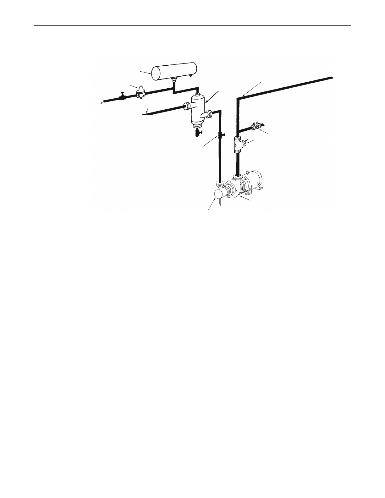
Typical installation
3
4
5
6
7
8
2
9
10
11
1
Installation
1. Compression tank (locate the compression tank on the suction side of the pump)
2. B&G Rolairtrol® air separator
3. Supply to system
4. B&G Circuit Setter
5. B&G Triple Duty® valve
6. B&G Series 1531 Pump
7. B&G Suction Diffuser
8. Isolation valve
9. Pipe from boiler, chiller, or converter
10. Cold water supply
11. B&G Reducing Valve
®
Series 1531 Installation, Operation, and Maintenance Manual 15
Page 18
Commissioning, Startup, Operation, and Shutdown
Commissioning, Startup, Operation,
and Shutdown
Preparation for startup
WARNING:
Explosion hazard. Do not short battery terminals together or damage the battery.
WARNING:
• Failure to follow these precautions before you start the unit will lead to serious personal
injury and equipment failure.
• Do not operate the pump below the minimum rated flows or with the suction or
discharge valves closed. These conditions can create an explosive hazard due to
vaporization of pumped fluid and can quickly lead to pump failure and physical injury.
• If the pump, motor, or piping operate at extremely high or low temperatures, then
guarding or insulation is required. Failure to follow these instructions can result in
serious personal injury or death, and property damage.
• Always disconnect and lock out power to the driver before you perform any installation
or maintenance tasks. Failure to disconnect and lock out driver power will result in
serious physical injury.
• Operating the pump in reverse rotation can result in the contact of metal parts, heat
generation, and breach of containment.
NOTICE:
• Verify the driver settings before you start any pump.
• Make sure that the warm-up rate does not exceed 2.5°F (1.4°C) per minute.
You must follow these precautions before you start the pump:
• Flush and clear the system thoroughly to remove dirt or debris in the pipe system in
order to prevent premature failure at initial startup.
• Bring variable-speed drivers to the rated speed as quickly as possible.
• If temperatures of the pumped fluid will exceed 200°F (93°C), then warm up the pump
prior to operation. Circulate a small amount of fluid through the pump until the casing
temperature is within 100°F (38°C) of the fluid temperature.
At initial startup, do not adjust the variable-speed drivers or check for speed governor or
over-speed trip settings while the variable-speed driver is coupled to the pump. If the
settings have not been verified, then uncouple the unit and refer to instructions supplied
by the driver manufacturer.
Prime the pump
CAUTION:
Do not run the pump dry.
16 Series 1531 Installation, Operation, and Maintenance Manual
Page 19
Make sure that the pump body is full of liquid before startup. If the system does not
automatically fill the pump body with liquid, then you must manually prime the pump.
1. Loosen the vent plugs on the pump body.
2. While venting the air from the pump body, rotate the pump shaft a few times by hand.
3. After all air has been purged from the pump, close the vent plugs.
Start the pump
CAUTION:
• Observe the pump for vibration levels, bearing temperature, and excessive noise. If
normal levels are exceeded, shut down the pump and resolve the issue.
Before you start the pump, you must perform these tasks:
• Open the suction valve.
• Open any recirculation or cooling lines.
1. Fully close or partially open the discharge valve, depending on system conditions.
2. Start the driver.
3. Slowly open the discharge valve until the pump reaches the desired flow.
4. Immediately check the pressure gauge to ensure that the pump quickly reaches the
5. If the pump fails to reach the correct pressure, perform these steps:
6. Monitor the pump while it is operating:
7. Repeat steps 5 and 6 until the pump runs properly.
Commissioning, Startup, Operation, and Shutdown
correct discharge pressure.
a) Stop the driver.
b) Prime the pump again.
c) Restart the driver.
a) Check the pump for bearing temperature, excessive vibration, and noise.
b) If the pump exceeds normal levels, then shut down the pump immediately and
correct the problem.
Pump operation precautions
General considerations
WARNING:
Do NOT exceed the maximum working pressure of the pump. This information is listed on
the nameplate of the pump.
CAUTION:
• Vary the capacity with the regulating valve in the discharge line. Never throttle the flow
from the suction side since this can result in decreased performance, unexpected heat
generation, and equipment damage.
• Do not overload the driver. Driver overload can result in unexpected heat generation
and equipment damage. The driver can overload in these circumstances:
• The specific gravity of the pumped fluid is greater than expected.
• The pumped fluid exceeds the rated flow rate.
• Make sure to operate the pump at or near the rated conditions. Failure to do so can
result in pump damage from cavitation or recirculation.
Series 1531 Installation, Operation, and Maintenance Manual 17
Page 20
Commissioning, Startup, Operation, and Shutdown
Operation at reduced capacity
WARNING:
Never operate any pumping system with a blocked suction and discharge. Operation,
even for a brief period under these conditions, can cause confined pumped fluid to
overheat, which results in a violent explosion. You must take all necessary measures to
avoid this condition.
CAUTION:
Avoid excessive vibration levels. Excessive vibration levels can damage the bearings,
stuffing box or seal chamber, and the mechanical seal, which can result in decreased
performance.
NOTICE:
• Avoid increased radial load. Failure to do so can cause stress on the shaft and
bearings.
• Avoid heat build-up. Failure to do so can cause rotating parts to score or seize.
• Avoid cavitation. Failure to do so can cause damage to the internal surfaces of the
pump.
Operation under freezing conditions
NOTICE:
Do not expose an idle pump to freezing conditions. Drain all liquid that is inside the pump.
Failure to do so can cause liquid to freeze and damage the pump.
Shut down the pump
1. Slowly close the discharge valve.
2. Shut down and lock the driver to prevent accidental rotation.
Note on the packed pump operation
Tighten the gland nuts
Before you start the pump, back off the packing gland nuts or screws until the gland is
loose.
Hand tighten until the gland is snug against the first packing ring. Initially, water might
freely run from the packing. This is normal and should be allowed to continue for a period
of time before you continue to tighten the gland. Tighten the gland nuts slowly and one
flat at a time.
Leakage rate
An adequate leakage rate is not one single value for all pumps and installations, but is the
amount required to provide adequate cooling and lubrication. The required leakage is
influenced by operating pressure, fluid temperature, shaft speed, and so forth. For fluid
temperatures in the range of 32°F to 190°F (0°C to 88°C), average leakage rates of 60 to
80 drops per minute are recommended. However, each individual pump and installation
has unique operating conditions that result in widely-variable leakage rate requirements.
18 Series 1531 Installation, Operation, and Maintenance Manual
Page 21

Maximum fluid temperature
At fluid operating temperatures near the upper limit of 190°F (88°C), the maximum
temperature rise of the leakage is important. Never operate a packed pump with steam
forming at the gland. This limits the temperature rise to a maximum of about 20°F (-7°C). If
the formation of steam persists at higher leakage rates, you must provide cooling water by
means of an external supply, or a heat exchanger used to cool the bypass flush.
Commissioning, Startup, Operation, and Shutdown
Series 1531 Installation, Operation, and Maintenance Manual 19
Page 22
Maintenance
Maintenance
Bearing maintenance
Bearing lubrication schedule
Type of bearing First lubrication Lubrication intervals
Motor bearings No initial lubrication. The motor was
Disassembly
Disassembly precautions
This manual clearly identifies accepted methods for disassembling units. These methods
must be adhered to.
WARNING:
• Make sure that the pump is isolated from the system and that pressure is relieved before
you disassemble the pump, remove plugs, open vent or drain valves, or disconnect the
piping.
• Always disconnect and lock out power to the driver before you perform any installation
or maintenance tasks. Failure to disconnect and lock out driver power will result in
serious physical injury.
• Crush hazard. The unit and the components can be heavy. Use proper lifting methods
and wear steel-toed shoes at all times.
NOTICE:
Make sure that all replacement parts are available before you disassemble the pump for
overhaul.
lubricated at the factory.
Refer to the motor manufacturer's
recommendations for lubrication
intervals.
Drain the pump
CAUTION:
• Allow all system and pump components to cool before you handle them to prevent
physical injury.
1. Close the isolation valves on the suction and discharge sides of the pump.
You must drain the system if no valves are installed.
2. Open the drain valve.
Do not proceed until liquid stops coming out of the drain valve. If liquid continues to
flow from the drain valve, the isolation valves are not sealing properly and you must
repair them before you proceed.
3. Leave the drain valve open and remove the drain plug located on the bottom of the
pump housing.
Do not reinstall the plug or close the drain valve until the reassembly is complete.
4. Drain the liquid from the piping and flush the pump if it is necessary.
5. Disconnect all auxiliary piping and tubing.
20 Series 1531 Installation, Operation, and Maintenance Manual
Page 23

Remove the bearing frame and impeller assembly
1. Remove the support foot capscrews.
2. Loosen the volute capscrews but do not remove them.
3. Loosen the bearing frame and impeller assembly from the volute.
WARNING:
Make certain that the internal pressure of the pump is relieved before
you continue. Failure to follow these instructions could result in serious
personal injury or death, or property damage.
4. Remove the seal flushing tube if it is used.
5. Remove the volute capscrews.
6. Remove the bearing frame and impeller assembly from the volute.
7. Remove the impeller capscrew, lock washer, and washer.
8. Remove the impeller.
Remove the mechanical seal (1531 and 1531-F)
1. Remove the rotating portion of the seal.
If necessary, use a screwdriver to loosen the rubber ring.
2. Remove the seal insert, the insert gasket, and the retainer if it is used.
Maintenance
Remove the seal or packing rings (1531-S, 1531-D, and 1531-PF)
1. Remove the hex nuts from the seal cap bolts.
2. For the 1531-PF, remove the hex nuts from the packing gland.
3. Remove the coverplate screws.
4. Remove the coverplate from the bracket.
5. Remove the seal assembly or packing rings.
Pre-assembly inspections
Guidelines
Before you assemble the pump parts, make sure you follow these guidelines:
• Inspect the pump parts according to the information in these pre-assembly topics
before you reassemble your pump. Replace any part that does not meet the required
criteria.
• Make sure that the parts are clean. Clean the pump parts in solvent in order to remove
oil, grease, and dirt.
NOTICE: Protect machined surfaces while you clean the parts. Failure to do so may
result in equipment damage.
Areas to inspect
Inspect the pump regularly for leaking seals, worn gaskets, and loose or damaged
components. Replace or repair these parts as required.
Shaft and sleeve inspection
Inspection criteria
Inspect the shaft and sleeve according to this criteria:
• Thoroughly clean the shaft and sleeve.
• Thoroughly clean the coverplate seal cavity.
• Inspect the surface for damage such as pitting, corrosion, nicks, and scratches.
Series 1531 Installation, Operation, and Maintenance Manual 21
Page 24
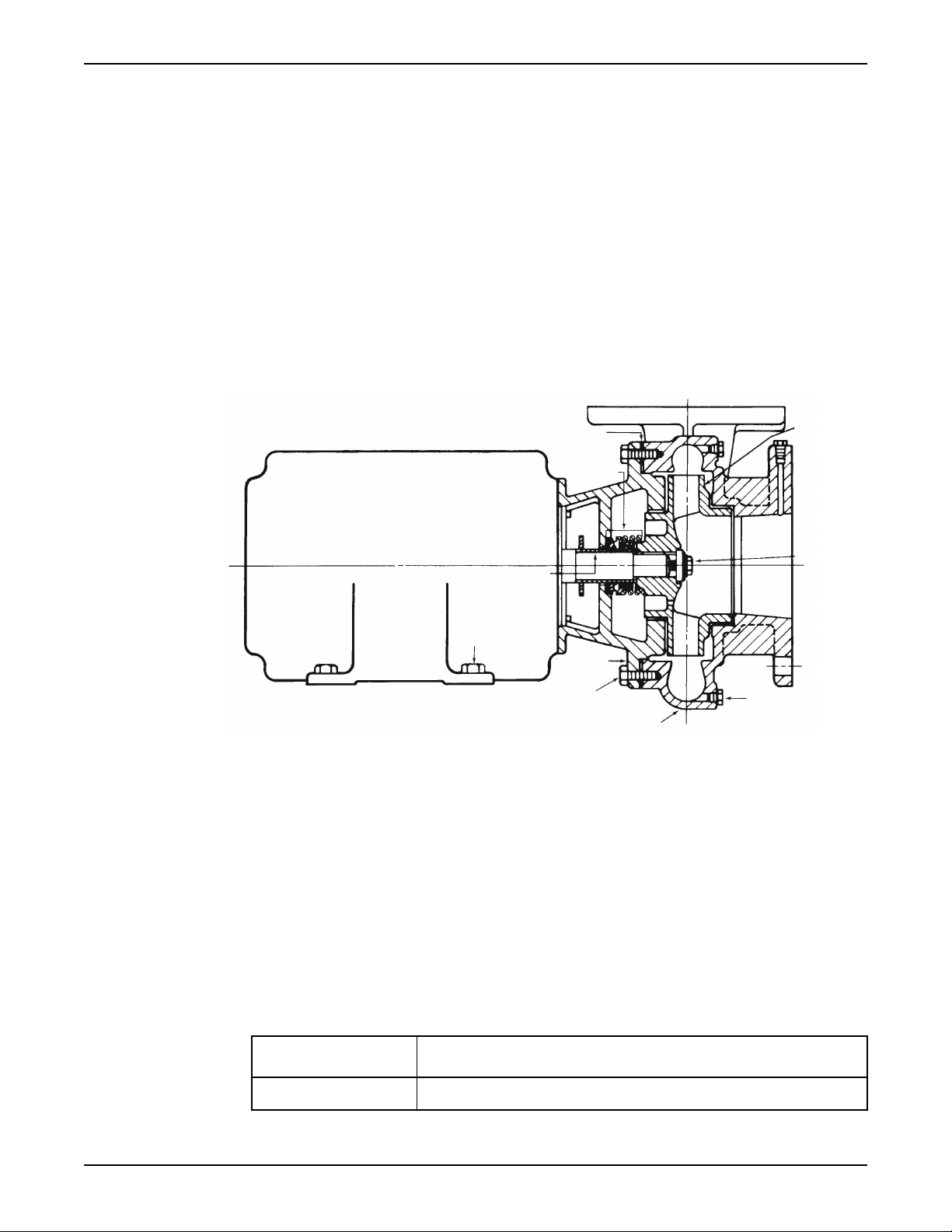
1
2
3
4
5
6
7
8
9
10
Maintenance
Replace these parts if they are damaged.
Reassembly
Seal assembly
Assemble the standard mechanical seal (1531 and 1531-F)
1. Lubricate the shaft sleeve and coverplate seal cavity with soapy water.
Do not use a petroleum lubricant.
2. Install a new cup gasket and a new seal insert with the indentation side down into the
cup.
3. Slide a new rotating seal assembly onto the shaft sleeve.
4. Push the top of the compression ring with a screwdriver until the seal is tight against
the seal insert.
5. Install the seal spring and point the narrow end toward the seal.
1. Impeller
2. Impeller capscrew
3. Drain plug
4. Volute
5. Volute capscrews
6. Motor bracket
7. Motor foot capscrews
8. Shaft sleeve
9. Seal assembly
10. Volute gasket
Assemble the single mechanical seal (1531-S)
1. Lubricate the shaft sleeve and seal cap with soapy water.
Do not use a petroleum lubricant.
2. Insert a stationary seal with an O-ring into the seal cap and slide it onto the shaft.
3. Replace the seal cap gasket.
4. Slide the rotating portion of the seal assembly onto the shaft sleeve and lock it in place.
ID seal size Distance between collar and impeller end of the shaft sleeve
1-1/4 in. (3.175 cm) 1-13/32 in. (3.571 cm)
22 Series 1531 Installation, Operation, and Maintenance Manual
Page 25
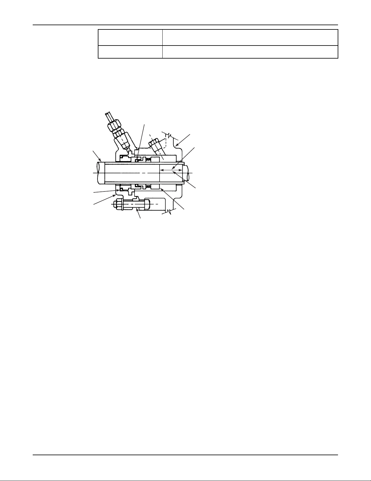
2
3
4
5
6
7
9
1
8
Maintenance
ID seal size Distance between collar and impeller end of the shaft sleeve
1-5/8 in. (4.128 cm) 1-1/4 in. (3.175 cm)
5. Assemble the coverplate onto the bracket.
6. Tighten the capscrews according to the Capscrew torque table.
7. Attach the seal cap to the coverplate.
8. Tighten the hex nuts on the seal cap bolts according to the Capscrew torque table.
1. O-ring
2. Coverplate
3. For 1-1/4 in. seal: 1-13/32 in. (3.571 cm)
4. For 1-5/8 in. seal: 1-1/4 in. (3.175 cm)
5. Seal locking collar
6. Seal cap bolt
7. Seal cap
8. O-ring
9. Motor end
Figure 2: Single mechanical seal (1531–S)
Assemble the double mechanical seal (1531-D)
1. Lubricate the shaft sleeve, seal cap, and coverplate cavity with soapy water.
Do not use a petroleum lubricant.
2. Insert a stationary seal and O-ring into the seal cap.
For the 1-1/4 in. ID seal, both parts are housed in the coverplate. A seal cap gasket is
not used.
Series 1531 Installation, Operation, and Maintenance Manual 23
Page 26

1
2
1
Maintenance
1. O-rings
2. Motor end
Figure 3: Double mechanical seal (1531–D)
3. Insert another stationary seal and O-ring into the coverplate.
4. Slide the seal cap onto the shaft.
5. Replace the seal cap gasket.
6. Slide the rotating portion of the seal assembly onto the shaft sleeve.
7. Assemble the coverplate onto the bracket.
8. Tighten the capscrews according to the Capscrew torque values table.
9. Attach the seal cap to the coverplate.
10. Tighten the hex nuts on the seal cap bolts according to the Capscrew torque values
table.
Assemble the packed stuffing box (1531-PF)
1. Insert two packing rings into the stuffing box.
2. Insert the lantern ring and the last two pieces of packing.
Make sure that the joints on the packing rings are staggered 90º.
3. Install, but do not tighten, the packing gland.
4. Install the coverplate over the pump shaft.
5. Tighten the capscrews according to the Capscrew torque table in the Maintenance
chapter.
6. Tighten the packing gland to compress the packing.
See the note on the packed pump operation in the Operations chapter for more
information.
24 Series 1531 Installation, Operation, and Maintenance Manual
Page 27

1
2
3
4
5
1. Flushing tube
2. Coverplate capscrew
3. Packing gland
4. Bracket
5. Coverplate
Maintenance
Reinstall the bearing frame and impeller assembly
1. Install the impeller, impeller washer, lock washer, and capscrew, and then tighten per
the Capscrew torque values table.
2. Install a new volute gasket.
3. Install the bearing frame assembly into the volute.
4. Tighten the volute capscrews according to the Capscrew torque values table.
5. Install a seal flushing tube if it is used.
6. Install the support foot capscrews and tighten them according to the Capscrew torque
values table.
7. Install the drain plug and close the drain valve.
8. Open the isolation valves and inspect the pump for leaks.
Return the pump to service if you do not detect any leaks. See the Note on the packed
pump operation in the Commissioning, Startup, Operations, and Shutdown chapter.
Capscrew torque values
Capscrew torque in ft-lbs (Nm)
Capscrew
type
SAE grade 2 6 (8) 13 (18) 25 (34) 38 (52) 60 (81) 120 (163) 190 (258) 210 (285) 300 (407)
Brass or
stainless
steel
Head
marking
or
1/4 in. 5/16 in. 3/8 in. 7/16 in. 1/2 in. 5/8 in. 3/4 in. 7/8 in. 1 in.
4 (5) 10 (14) 17 (23) 27 (37) 42 (57) 83 (113) 130 (176) 200 (271) 300 (407)
Series 1531 Installation, Operation, and Maintenance Manual 25
Page 28

Maintenance
Capscrew
type
SAE grade 5 10 (14) 20 (27) 35 (47) 60 (81) 90 (122) 180 (244) 325 (441) 525 (712) 800 (1085)
Head
marking
1/4 in. 5/16 in. 3/8 in. 7/16 in. 1/2 in. 5/8 in. 3/4 in. 7/8 in. 1 in.
Dealer servicing
If trouble occurs that cannot be rectified, contact your local sales and service
representative and be prepared to provide this information:
1. Complete nameplate data of pump and motor
2. Suction and discharge pipe pressure gauge readings
3. Ampere draw of the motor
4. A sketch of the pump hook-up and piping
26 Series 1531 Installation, Operation, and Maintenance Manual
Page 29

Page 30

Xylem |’zīləm|
1) The tissue in plants that brings water upward from the roots
2) A leading global water technology company
We're 12,500 people unified in a common purpose: creating
innovative solutions to meet our world's water needs. Developing new
technologies that will improve the way water is used, conserved, and
re-used in the future is central to our work. We move, treat, analyze,
and return water to the environment, and we help people use water
efficiently, in their homes, buildings, factories and farms. In more than
150 countries, we have strong, long-standing relationships with
customers who know us for our powerful combination of leading
product brands and applications expertise, backed by a legacy of
innovation.
For more information on how Xylem can help you, go to xyleminc.com
Xylem Inc.
8200 N. Austin Avenue
Morton Grove, IL 60053
Tel. 1-847-966-3700
Fax 1-847-965-8379
www.xyleminc.com/brands/
bellgossett
Visit our Web site for the latest version of this
document and more information
The original instruction is in English. All nonEnglish instructions are translations of the original
instruction.
©
2012 Xylem Inc.
Bell & Gossett is a trademark of Xylem Inc or one
of its subsidiaries.
P81567_F_ en.US_2012 -12_IOM.1531
 Loading...