

Page 1
INSTRUCTION MANUAL
P81555D
Series 1510
Based Mounted
Centrifugal Pump Kits
IMPORTANT
The Series 1510 pump kits are to assembled by qualified personnel only. Any questions regarding the assembly procedure
should be referred to the Bell & Gossett Service Manager.
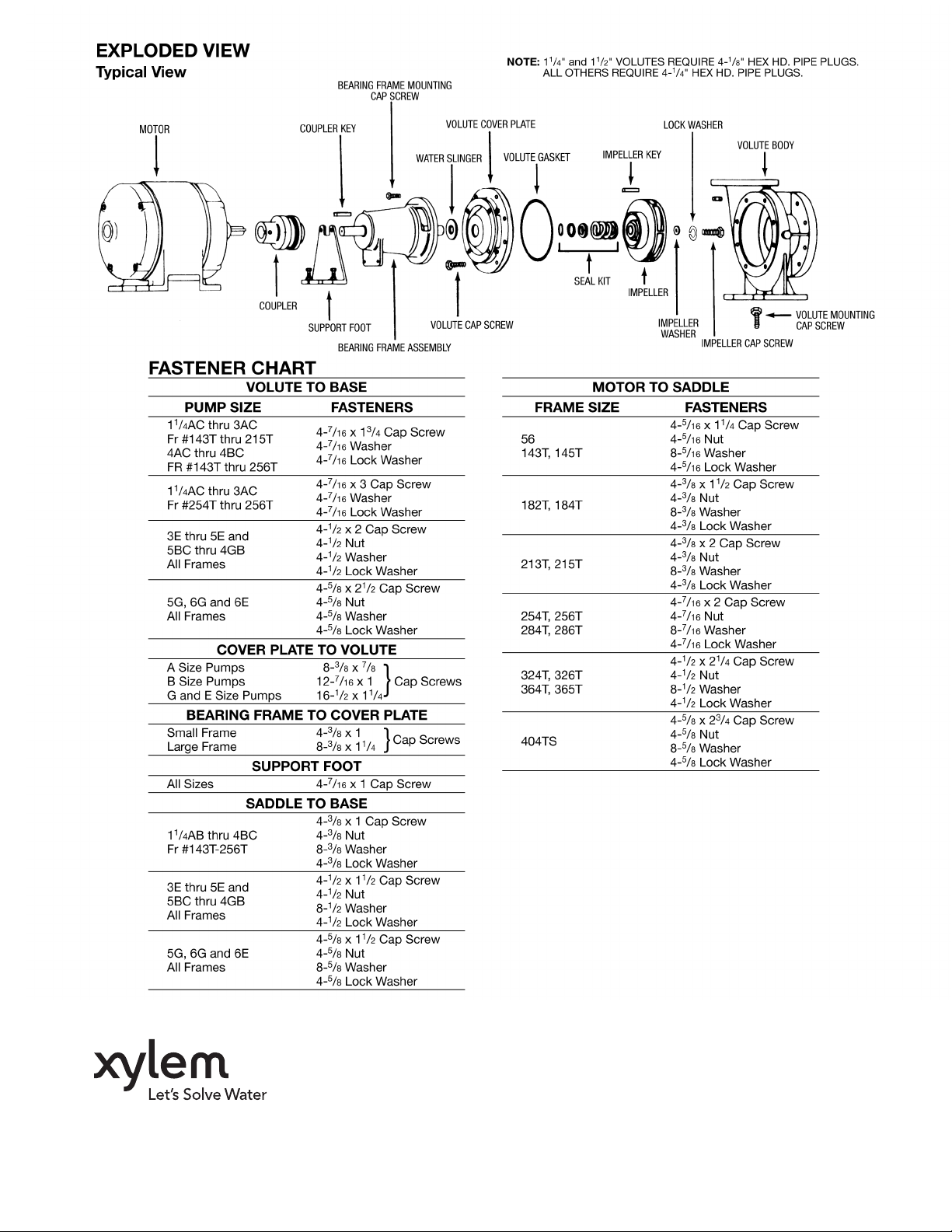
Impeller cap screws and washers are furnished with the kit. All
other fasteners and shims must be furnished by assembler.
(Refer to Fastener Chart for proper sizing of cap screws, nuts
and washers.)
1. Mount volute to base, adding a minimum of .025" in shims
between volute and base. Use 4 cap screws, 4 lock
washers, 4 flat washers and risers when applicable.
2. Assemble volute cover plate to small bearing assembly
(1" shaft) with 4 cap screws. On large bearing assembly
1
(1
/4" shaft), use 8 cap screws.
3. Press seal insert in volute cover plate. Push pump shaft
forward from rear of bearing assembly to take up end play.
Moisten the inner diameter of seal assembly with soapy
water, maintaining forward pressure on the shaft, and press
seal firmly in place. Carbon seal face must be tight against
ceramic insert. Apply small end of tapered spring on seal.
4. Make certain that impeller has been properly cut to size for
required GPM and feet of head and balanced. Slide impeller
onto bearing assembly shaft until it bottoms against the
shaft shoulder. Fasten impeller using one cap screw, one
internal lock washer and one large impeller washer. Make
certain that cap screw is tightened to 18-20 foot pounds on
small bearing assembly (1" shaft) and 40-44 foot pounds on
the large bearing assembly (1
5. Mount bearing assembly, impeller, volute gasket and cover
plate to volute.
6. Add foot support to base and bearing frame using 4 cap
screws, 4 lock washers, 4 flat washers and 4 nuts. In some
instances, the nuts will be welded direct to the base cross
member.
7. Mount saddle to base with 4 cap screws, 4 lock washers,
8 flat washers and 4 nuts.
1
/4" shaft).
8. Mount motor to saddle using 4 cap screws, 4 lock washers,
8 flat washers and 4 nuts.
9. Apply pump coupler half to pump shaft and motor coupler
half to motor shaft. Tighten one coupler half in its final position and add coupler sleeve. If using a two piece sleeve, hang
the wire ring loosely in the groove next to the teeth. Slide
the loose flange tightly up against the sleeve and back off
1
/8" for axial clearance. Tighten the loose flange to the shaft.
Check vertical and horizontal misalignment by using a
straight edge scale or piece of bar stock
notched to provide clearance for the raised portion of the
coupler sleeve. For 3500 rpm operation, it will be necessary
to check the angular misalignment by using a dial indicator
or micrometer calipers. Measure the gap at intervals around
the periphery of the coupling to determine minimum and
maximum gap. The difference between these two values
should be as close to zero as possible.
If the angular alignment was adjusted, it will be necessary to
recheck the vertical and horizontal misalignment again.
If using a two piece sleeve, force the wire ring into its
groove in the center of the sleeve. The use of a blunt screw
driver may be necessary.
10. Apply coupler guard using 4 cap screws, 4 lock washers
and 4 nuts.
11. Recheck all exposed nuts and cap screws for tightness.
12. Complete all name plate data and affix to base.
13. Complete and return Pump Kit Data Card to the Customer
Service Dept., Bell & Gossett, 8200 N. Austin Ave.,
Morton Grove, IL 60053.
14. Affix installation and service instructions (P81673).
15. Make certain complete unit is properly lubricated.
with the center
Page 2
Xylem Inc.
8200 N. Austin Avenue
Morton Grove, Illinois 60053
Phone: (847) 966-3700
Fax: (847) 965-8379
www.xyleminc.com/brands/bellgossett
Bell & Gossett is a trademark of Xylem Inc. or one of its subsidiaries.
© 2012 Xylem Inc. P81555D May 2012
 Loading...