

Page 1
Bell & Gossett
Instruction Manual P80925B
WARNING LABEL PART NO. V56871
INSTALLED ON PRODUCT. IF
MISSING, IT MUST BE REPLACED
™
ZoneTrol
Zone Pump Controller
Models ZT-2, ZT-3, ZT-4 & ZT-6
Installation, Operation and Service Instructions
INSTALLER: PLEASE LEAVE THIS MANUAL FOR THE OWNER’S USE.
SAFETY
INSTRUCTION
This safety alert symbol will be used in this manual to draw
attention to safety related instructions. When used, the safety
alert symbol means ATTENTION! BECOME ALERT! YOUR
SAFETY IS INVOLVED! FAILURE TO FOLLOW THESE INSTRUCTIONS MAY RESULT IN A SAFETY HAZARD.
DESCRIPTION
The ZoneTrol is a ready-to-install multiple-zone controller for
circulator pumps in hydronic systems. The ZoneTrol controllers feature switchable priority, powerful transformer, automatic resetable fuse and a built-in 30 minute timer on priority
circuit. The units are operated by two-wire 24-volt thermostats and requires connection to a 120 V, 60 Hz source voltage.
Maximum Maximum Single Phase Motor Rating
No. of Zones Type Current Voltage Temperature 120 V AC 240 V AC
ZT-2 2
ZT-3 3
ZT-4 4
ZT-6 6
120V, 60HZ; 20VA
120V, 60HZ; 30VA
BEFORE STARTING THE JOB
Please read instructions completely before starting work
All work must be performed by qualified personnel in
accordance with all applicable codes and ordinances.
Electrical connections must be made using copper wire
only.
The applications for the ZoneTrol zone pump controllers are
too numerous to show all the various illustrations for the different models. The ZT-4 (four zone) and ZT-2 (two zone) pump
controller will be illustrated in this manual for installation and
application purposes. The other multiple zone pump controllers are installed in a similar matter. The circuit diagrams
indicate the proper terminals for wiring the ZoneTrol for most
applications.
501A 580.0TSPD °F (40°C) 10A, 1/3 HP 10A, 1/2 HP
)yaleR hcaE(tneibmAremrofsnarTtatsomrehTyaleRsrebmuNledoM
Page 2
MECHANICAL INSTALLATION INSTRUCTIONS
The ZoneTrol unit should be securely mounted on a wall, shelf,
or partition near the pumps using four #8 screws (not included).
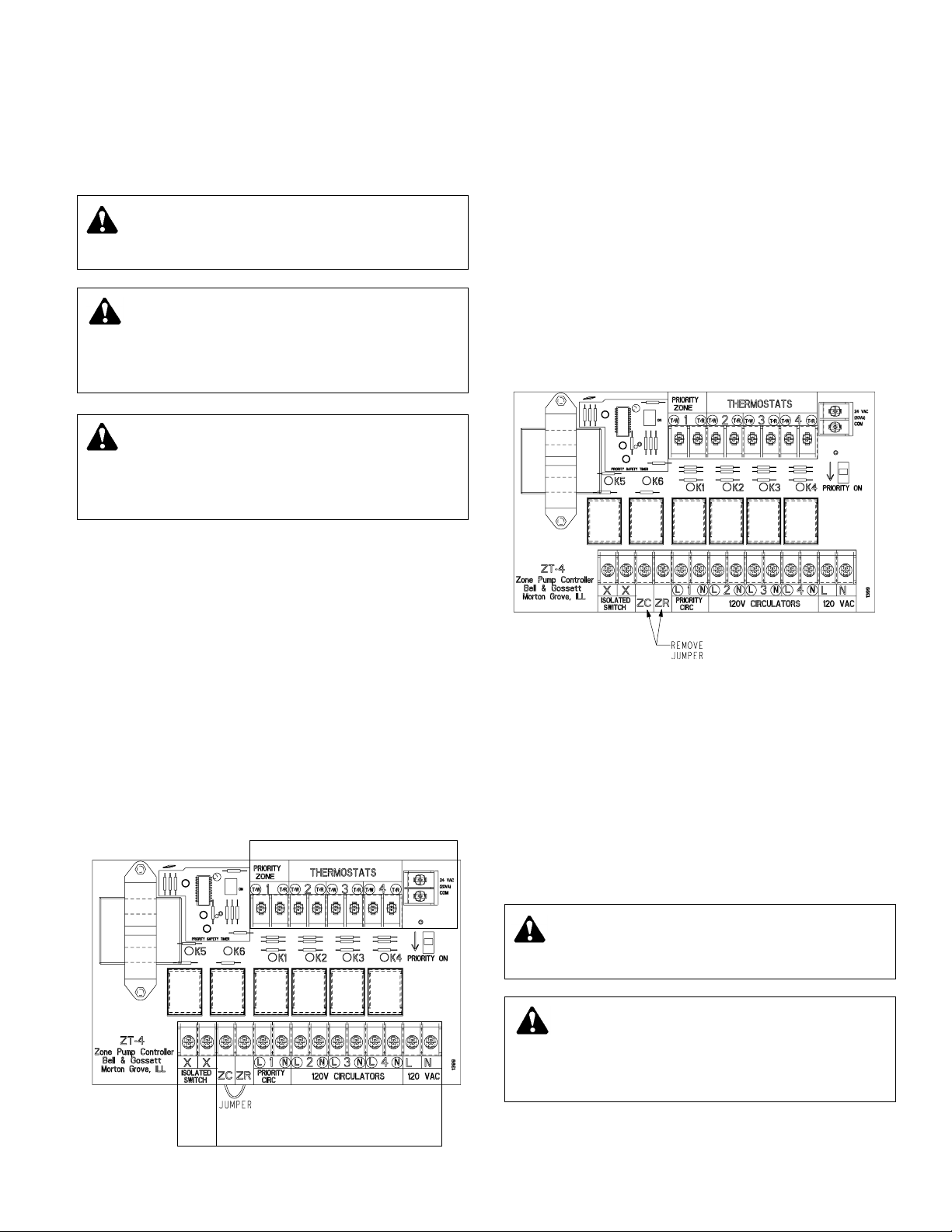
ELECTRICAL INSTALLATION INSTRUCTIONS
FOR MODELS ZT-4 AND ZT-6
“Cold Start” Boiler Applications
The “cold start” boiler application provides circulator operation
whenever a zone thermostat calls for heat (regardless of boiler
water temperature) and will start the burner when used in conjunction with an isolated end switch connected to the aquastat
on the boiler.
1) A factory installed jumper is connected between the ZC/ZR
terminals. Leave the jumper in its current position.
2) Attach the low voltage SPST thermostat leads to the
respective thermostat teminals.
3) Attach circulator leads to respective terminals.
4) Connect supply voltage line to the terminals marked 120
VAC, located on the lower right side of the circuit board.
5) Connect isolated switch (terminals XX) to TT terminals on
boiler aquastat.
Note: The required aquastat connections
may vary, depending on model. Refer to aquastat manufacturers’ instructions to ensure appropriate interconnections.
2
WARNING: Electrical shock and potential circuit
damage. Disconnect power supply before beginning
installation. Failure to follow these instructions could result
in serious personal injury or death and property damage.
WARNING: Improper wiring and wire can cause elec-
trical shock and fires. Wiring connections must be
made in accordance with all applicable electrical codes and
ordinances. Use copper wire only. Failure to follow these
instructions could result in serious personal injury or death
and property damage.
JUMPER
WARNING: Electrical shock and potential circuit
damage. Disconnect power supply before beginning
installation. Failure to follow these instructions could result
in serious personal injury or death and property damage.
WARNING: Improper wiring and wire can cause elec-
trical shock and fires. Wiring connections must be
made in accordance with all applicable electrical codes and
ordinances. Use copper wire only. Failure to follow these
instructions could result in serious personal injury or death
and property damage.
WARNING: Potential electrical overload. Each circuit
is limited to a maximum of 10 amps and
1
/3 HP. The
combined load for the controller is limited to 20 amps and
1 HP maximum. Failure to follow these instructions could
result in serious personal injury or death and property
damage.
“Tankless Coil” Boiler Applications
The “tankless coil” boiler application activates the boiler and
permits circulator operation only after boiler water has reached
the low temperature limit settings. If boiler temperatures drop
below the low limit setting, all circulators will cease operation
until the low limit temperature of the boiler is satisfied.
1) A factory installed jumper is connected between the ZC/ZR
terminals. Remove the jumper.
2) Connect the ZC/ZR terminals to the corresponding ZC/ZR
terminals on the boiler aquastat. The XX terminals are not
used.
Note: The required aquastat connections may vary,
depending on model. Refer to aquastat manufacturers'
instructions to ensure appropriate interconnections
3) Attach the low voltage SPST thermostat leads to the
respective thermostat teminals.
4) Attach circulator leads to respective terminals.
5) Connect supply voltage line to the terminals marked 120
VAC, located on the lower right side of the circuit board.
Priority
If the priority switch is in the ON position, Zone 1 is the priority
zone. When the priority zone 1 circulator is actuated, the other
circulators will not operate. The ZoneTrol has a 30 minute
timer on the priority zone. After 30 minutes of continous operation, the priority zone function will default allowing all zones
to operate preventing possible house freeze up. The timer is
automatically reset after the priority zone is satisfied.
If the priority switch is not in the ON position, all zones operate
independent of each other.
ELECTRICAL INSTALLATION INSTRUCTIONS
FOR MODELS ZT-2 AND ZT-3
Class 2 Terminals
Primary Terminals
Class 2
Terminals
Page 3

“Tankless Coil” Boiler Applications
The “tankless coil” boiler application activates the boiler and
permits circulator operation only after boiler water has reached
the low temperature limit settings. If boiler temperatures drop
below the low limit setting, all circulators will cease operation
until the low limit temperature of the boiler is satisfied.
1) A factory installed jumper is connected between the L1/ZC
terminals. Move the jumper to the terminal as shown on
the circuit board.
2) Attach the low voltage SPST thermostat leads to the
respective thermostat teminals.
3) Attach circulator leads to respective terminals.
4) Connect supply voltage line to the L1 and L2 terminals
located in the lower center portion of the circuit board.
5) Connect the ZC/ZR terminals to the corresponding ZC/ZR
terminals on the boiler aquastat. The XX terminals are not
used.
Note: The required aquastat connections may vary,
depending on model. Refer to aquastat manufacturers'
instructions to ensure appropriate interconnections.
Priority
The ZT-2 and ZT-3 pump controllers are supplied from factory
ready for priority applications. When the priority zone 1 circulator is actuated, the other circulator(s) will not operate. The
ZoneTrol has a 30 minute timer on the priority zone. After
30 minutes of continous operation, the priority zone function
will default allowing all zones to operate preventing possible
house freeze up. The timer is automatically reset after the
priority zone is satisfied.
For applications where priority is not desired, add second
jumper (remove one from L1 and ZC terminals) between the
terminals that are marked “ADD JUMPER FOR PRIORITY
OFF” and cut jumper wire between S-J (see drawing). This will
disable the priority feature allowing all zones to operate independent of each other.
SERVICE INSTRUCTIONS
The ZoneTrol is quality constructed and should provide many
years of trouble-free service when installed and operated in
accordance with the instruction manual. To ensure optimum
long-term performance, once each heating season, visually
inspect the unit to check the condition of the contacts on the
plug-in replaceable relays. Replace the relay(s) if contacts
appear pitted or severely blackened.
The 24 volt fuse is temperature sensitive and will automatically
reset after a couple of minutes cooling time.
WARNING: Potential electrical shock. Disconnect all
power to unit before removing chassis cover. Failure
to follow these instructions could result is serious personal
injury or death and property damage.
3
“Cold Start” Boiler Applications
The “cold start” boiler application provides circulator operation
whenever a zone thermostat calls for heat (regardless of boiler
water temperature) and will start the burner when used in conjunction with an isolated end switch connected to the aquastat
on the boiler.
1) A factory installed jumper is connected between the L1/ZC
terminals. Leave the jumper in this position.
2) Attach the low voltage SPST thermostat leads to the
respective thermostat teminals.
3) Attach circulator leads to respective terminals.
4) Connect supply voltage line to the terminals L1 and L2,
located in the lower center portion of the circuit board.
5) Connect isolated switch (terminals XX) to TT terminals on
boiler aquastat.
Note: The required aquastat connections
may vary, depending on model. Refer to aquastat manufacturers’ instructions to ensure appropriate interconnections.
WARNING: Potential electrical overload. Each relay
is limited to a maximum of 10 amps and
1
/3 HP. The
combined load for the controller is limited to 20 amps and
1 HP maximum. Failure to follow these instructions could
result in serious personal injury or death and property
damage.
Page 4

WARNING: Improper wiring and wire can cause electrical shock and fires. The wiring dia-
grams shown provide interconnection recommendations only. The aquastat manufacturers’
detailed wiring instructions must be followed to insure proper electrical connections to other
system components including burner control, gas valve or limit control. All work must be performed by qualified personnel in accordance with applicable codes and ordinances. Electrical
connections must be made using copper wire only. Failure to follow these instructions could
result in serious personal injury or death and property damage.
FIGURE 1
(Cold Start Boiler)
ZT-4 to MH L8148
FIGURE 2
(Tankless Coil Boiler)
ZT-4 to MH L8124 A or C
4
FIGURE 3
(Cold Start Boiler)
ZT-4 to Millivolt Gas Valve
Page 5

FIGURE 5
(Cold Start Boiler)
ZT-4 to MH L8148
5
FIGURE 4
(Tankless Coil Boiler)
ZT-4 to MH L60081A, L4006A, L6006A
FIGURE 6
ZT-4 to Field Replaceable Transformer
Page 6

7
6
10
9
4
1
100% factory tested –
1
limited 5 year warranty.
Separate XX isolated end switch and ZC/ZR
2
relays protect boiler aquastat. Can be used with
“tankless coil” or “cold start” applications.
Replaceable, standard “ice cube” type relays allow
3
up to 10 amps, 1/3 HP per individual zone.
Powerful 30 VA transformer operates
4
up to 6 zones.
Switchable priority adds versatility and ease
5
of installation.
8
3
2
10
30 minute built-in safety priority timer helps prevent
6
house freeze up – no additional plug-in cards required.
Automatically resetable fuse protects controller
7
from overload – Eliminate “no heat” call backs due
to blown fuse.
LED dianostic lights for easy trouble shooting are
8
installed internally for heating professional’s use –
no more calls from curious homeowners inquiring
about flashing lights.
24 volt I/O terminal for connection of 3 wire thermostats
9
or field replacement of transformer.
Clearly marked terminals and plenty of clearance make
10
for easy, fast hook-up.
5
OPERATION
The circulators wired to the ZoneTrol pump controller are controlled by a low voltage thermostat or any other low voltage
controller having a SPST switch. The relays provide intermediate switching to permit line voltage to the circulators. The
ZoneTrol will operate with most digital/programmable thermostats. The isolated end switch relay (terminals XX) has a full
10 amp rating. The resetable fuse protects the ZoneTrol from
overloading conditions.
The following sequence occurs when the ZT-4 has a call for
heat:
1. Isolated switch relay closes.
2. XX switch is closed.
3. XX indicator light turns on.
4. Control relay closes. (ZC and ZR connection required either
by factory installed jumper or through aquastat)
© COPYRIGHT 2006 BY
PRINTED IN U.S.A. 12-06
8200 N. Austin Avenue
Morton Grove, IL 60053
Phone: (847) 966-3700
Fax: (847) 966-9052
http://www.bellgossett.com
OPERATION
5. ZC indicator light turns on.
6. Zone circulator starts.
7. Respective zone light indicator turns on.
If priority switch is in ON position:
1. Zone 1 becomes priority zone.
2. When priority zone 1 circulator is actuated, the other circulators will not operate.
3. The ZoneTrol has a 30 minute timer on the priority zone.
After 30 minutes of continuous operation, the priority zone
will default to allow all other zone to operate in order to prevent house freeze up. The timer is reset after the priority
zone is satisfied.
 Loading...