

Page 1
Bell & Gossett
Instruction Manual P80922A
WARNING LABEL PART NO. V56871
INSTALLED ON PRODUCT. IF
MISSING, IT MUST BE REPLACED
™
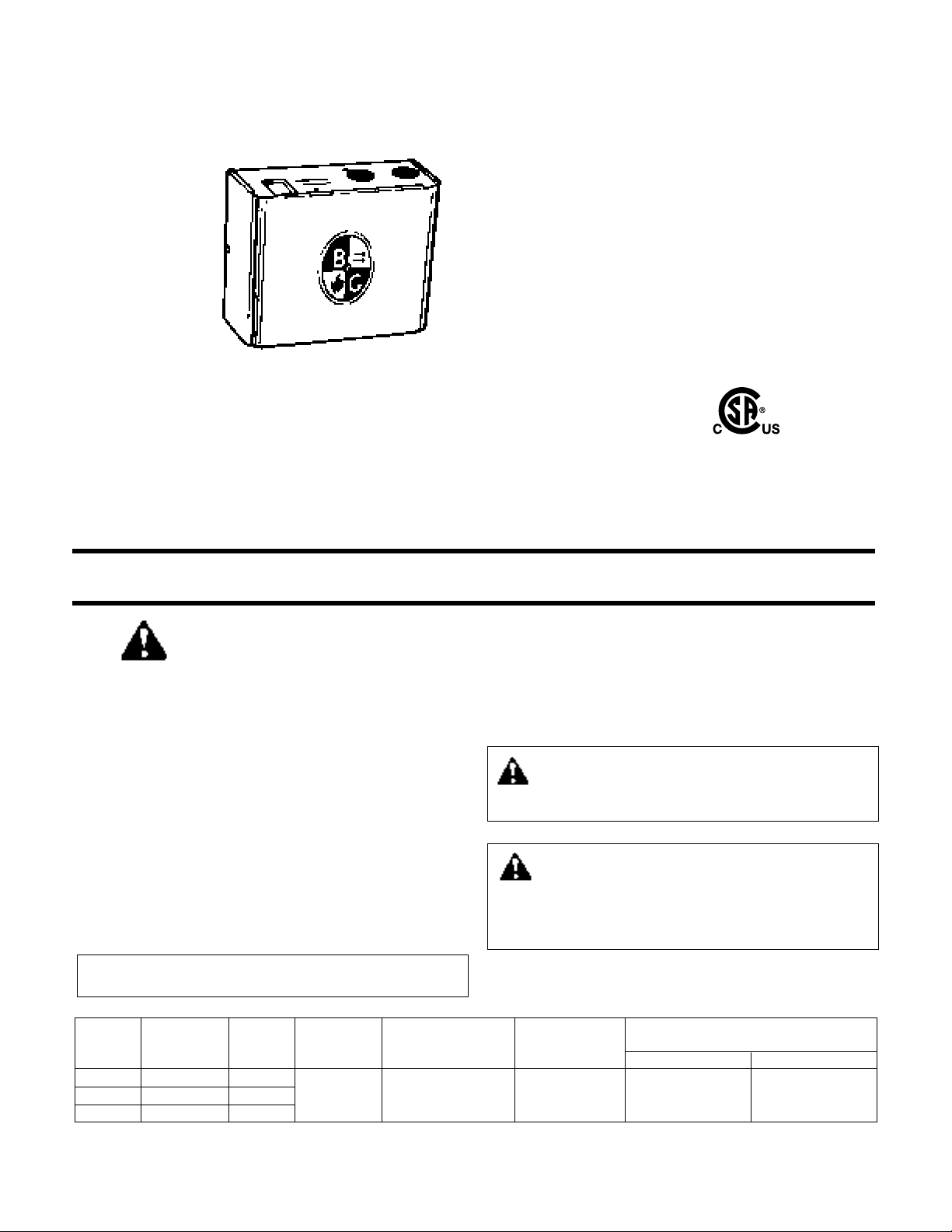
ZoneTrol
Pump Controller
Models ZT-1X, ZT-1XH, ZT-2X
Installation, Operation and Service Instructions
INSTALLER: PLEASE LEAVE THIS MANUAL FOR THE OWNER’S USE.
SAFETY
INSTRUCTION
This safety alert symbol will be used in this manual to draw
attention to safety related instructions. When used, the safety
alert symbol means ATTENTION! BECOME ALERT! YOUR
SAFETY IS INVOLVED! FAILURE TO FOLLOW THESE INSTRUCTIONS MAY RESULT IN A SAFETY HAZARD.
DESCRIPTION
The ZoneTrol Model ZT-1X and ZT-1XH are ready-to-install
single-zone controller for circulator pumps in hydronic systems. The ZT-2X is a two-zone pump controller. The ZoneTrol
controllers feature interchangeable plug-in/plug-out relay, 15
VA transformer, 10 amp rating and quick connect terminals.
The units are operated by two-wire 24-volt thermostats and
requires connection to 120 V, 60 Hz source voltage.
BEFORE STARTING THE JOB
Please read instructions completely before starting work
All work must be performed by qualified personnel in
accordance with all applicable codes and ordinances.
Maximum Maximum Single Phase Motor Rating
No. of Zones Type Current Voltage Temperature 120 VAC 240 VAC
ZT ZH 06 ,V021TDPD1X1-
ZT-1XH 1 DPST 0.18 A 15VA 105°F (40°C) 10 A, 1/3 HP 10A, 1/2HP
ZT-2X 2 DPST
MECHANICAL INSTALLATION INSTRUCTIONS
The ZoneTrol unit should be securely mounted on a wall, shelf,
or partition near the pumps using four #8 screws (not included).
ELECTRICAL INSTALLATION INSTRUCTIONS
Electrical connections must be made using copper wire only.
WARNING: Electrical shock and potential circuit
damage. Disconnect power supply before beginning
installation. Failure to follow these instructions could result
in serious personal injury or death and property damage.
WARNING: Improper wiring and wire can cause elec-
trical shock and fires. Wiring connections must be
made in accordance with all applicable electrical codes and
ordinances. Use copper wire only. Failure to follow these
instructions could result in serious personal injury or death
and property damage.
)yaleR hcaE(tneibmAremrofsnarTtatsomrehTyaleRsrebmuNledoM
Page 2

ELECTRICAL INSTALLATION
INSTRUCTIONS CONT.
ZT-1X and ZT-1XH
The applications for the ZoneTrol pump controllers are too
numerous to show all the various illustrations for the different
models. The circuit diagrams shown in this manual indicate
the proper terminals for wiring the ZT-1X and ZT-1XH controllers for most applications.
ZT-2X
“Cold Start” Boiler Applications
The “Cold start” boiler application provides circulator operation whenever a zone thermostat calls for heat (regardless of
boiler water temperature).
1) A factory installed jumper is connected between L and
W
terminals. Leave the jumper in its current position.
2) Attach the low voltage SPST thermostat leads to the
respective thermostat teminals.
3) Attach circulator leads to respective terminals.
4) Connect the 120 VA supply line to the terminals marked
G
ground and L hot.
5) In this arrangement, the
A
and
R
terminals become the
isolated end switch. Connect the
A
and
R
terminals to
the TT terminals on the boiler aquastat.
Note: The required
aquastat connections may vary, depending on model.
Refer to aquastat manufacturers’ instructions to ensure
appropriate interconnections.
“Tankless Coil” Boiler Applications
The “tankless coil” boiler application activates the boiler and
permits circulator operation only after boiler water has reached
the low temperature limit setting. If the boiler temperature drops
below the low limit setting, all circulators will cease operation
until the low limit temperature of the boiler is satisfied.
SERVICE INSTRUCTIONS
The ZoneTrol is quality constructed and should provide many
years of trouble-free service when installed and operated in
accordance with the instruction manual. To ensure optimum
long-term performance, once each heating season, visually
inspect the unit to check the condition of the contacts on the
plug-in relays. Replace the relay(s) if contacts appear pitted or
severely blackened.
2
WARNING: Potential electrical overload. Each circuit
is limited for a maximum of 10 amps and
1
/3 HP for
115V or
1
/2 HP for 230V. Do not overload circuit. Failure to
follow these instructions could result in serious personal
injury or death and property damage.
1) A factory installed jumper is connected between the
W
and
the L terminals. Remove the jumper and place between
terminals L and A .
2) Attach the low voltage SPST thermostat leads to the
respective thermostat teminals.
3) Attach circulator leads to respective terminals.
4) Connect the 120 VA supply line to the terminals marked
G
ground and
H
hot.
5) In this arrangement, line voltage is sent out
R
to the ZR
terminal on the aquastat and returned to
W
from the ZC
terminal on the aquastat.
Note: The required aquastat
connections may vary, depending on model. Refer to
aquastat manufacturers’ instructions to ensure appropriate
interconnections.
WARNING: Potential electrical shock. Disconnect all
power to unit before removing chassis cover. Failure
to follow these instructions could result is serious personal
injury or death and property damage.
WARNING: With jumper placed between terminals
A
and L , a line voltage is present. Connection from
these terminals to low voltage terminal could result in serious personal injury or death and property damage.
WARNING: Improper wiring and wire can cause elec-
trical shock and fires. The wiring diagrams shown on
following pages provide interconnection recommendations
only. The aquastat manufacturers’ detailed wiring instructions must be followed to insure proper electrical connections to other system components including burner control,
gas valve or limit control. All work must be performed by
qualified personnel in accordance with applicable codes
and ordinances. Electrical connections must be made using
copper wire only. Failure to follow these instructions could
result in serious personal injury or death and property
damage.
Class 2 Terminals
Primary Terminals
Page 3

3
Page 4

© COPYRIGHT 2006 BY
PRINTED IN U.S.A. 12-06
8200 N. Austin Avenue
Morton Grove, IL 60053
Phone: (847) 966-3700
Fax: (847) 966-9052
http://www.bellgossett.com
 Loading...