

Page 1
Replacement Seal Instructions for
INSTRUCTION MANUAL
Close-Coupled and Base Mounted
Centrifugal Pumps
SAFETY
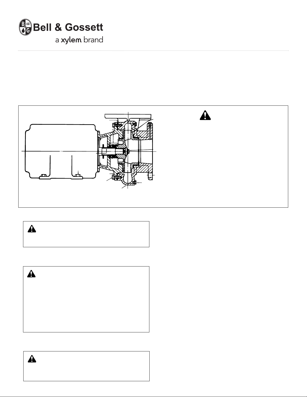
VOLUTE
GASKET
SEAL
ASSEMBLY
SHAFT SLEEVE
MOTOR FOOT
CAPSCREWS
MOTOR
BRACKET
VOLUTE
CAPSCREWS
CLOSE-COUPLED PUMP
VOLUTE
DRAIN PLUG
IMPELLER
IMPELLER
CAPSCREW
This safety alert symbol will be used in this manual and on the
pump safety instruction decals to draw attention to safety
related instructions. When used the safety alert symbol means
ATTENTION! BECOME ALERT! YOUR SAFETY IS INVOLVED!
FAILURE TO FOLLOW THE INSTRUCTIONS MAY RESULT IN A
SAFETY HAZARD.
NOTE: For additional information and instructions, refer to the
Installation Operation & Service Instructions Manual supplied
with your pump.
INSTRUCTIONS
P71000B
SERVICE INSTRUCTIONS
1.
2. Close valves on suction and discharge sides of pump. (If no
3.
4. Remove motor foot capscrews. Loosen volute capscrews, do
WARNING: UNEXPECTED STARUP HAZARD
Disconnect and lock out power before servicing.
Failure to follow these instructions could result in serious
personal injury or death, or property damage.
valves have been installed, it will be necessary to drain the
system.)
CAUTION: EXTREME TEMPERATURE HAZARD
Allow pump temperature to reach acceptable levels
before proceeding. Open drain valve, do not proceed until
liquid stops coming out of drain valve. If liquid does not
stop flowing from drain valve, isolation valves are not sealing and should be repaired before proceeding. After liquid
stops flowing from the drain valve, leave valves open and
continue. Remove the drain plug located on the bottom of
the pump housing. Do not reinstall plug or close drain valve
until re-assembly is completed.
Failure to follow these instructions could result in property
damage and/or moderate personal injury.
not remove them. Use capscrews in the jack screw holes.
Start to remove the pump assembly from the volute.
WARNING: EXCESSIVE PRESSURE HAZARD
Make certain internal pressure of the pump is relieved
before continuing.
Failure to follow these instructions could result in serious
personal injury or death, or property damage.
5. Remove seal flushing tube, if used. Remove the volute capscrews and remove the pump assembly from the volute.
6. Remove the impeller capscrews, lock washer and washer.
Remove the impeller.
7. Remove the rotating portion of the seal, use a screwdriver to
loosen the rubber ring.
8. Remove the seal insert along with the insert gasket and
retainer (if used).
9. Thoroughly clean the shaft sleeve and the coverplate seal
cavity. Inspect for surface damage like pitting, corrosion,
nicks or scratches. Replace if necessary.
10. Lubricate the shaft sleeve and coverplate seal cavity with
soapy water. (Do not use petroleum lubricant. ) Install a new
cup gasket and a new seal insert with indentation side down
into the cup.
11. Slide a new rotating seal assembly onto the shaft sleeve.
With a screwdriver push on the top of the compression ring
until the seal is tight against the seal insert. Install seal spring.
12. Install impeller, impeller washer. lock washer and capscrew,
then tighten capscrews (per torque chart).
13. Install new volute gasket then install pump assembly into
volute. Tighten volute capscrews (per torque chart). Install
seal flushing tube, if used. Install motor foot capscrews and
tighten. Install drain plug, close drain valve.
14. Open isolation valves, inspect pump for leaks, if not leaking
return pump to service.
Page 2
1.
WARNING: UNEXPECTED STARUP HAZARD
Disconnect and lock out power before servicing.
Failure to follow these instructions could result in serious
personal injury or death, or property damage.
2. Close valves on suction and discharge sides of pump. (If no
valves have been installed, it will be necessary to drain the
system.)
3.
CAUTION: EXTREME TEMPERATURE HAZARD
Allow pump temperature to reach acceptable levels
before proceeding. Open drain valve, do not proceed until
liquid stops coming out of drain valve. If liquid does not
stop flowing from drain valve, isolation valves are not sealing and should be repaired before proceeding. After liquid
stops flowing from the drain valve, leave valves open and
continue. Remove the drain plug located on the bottom of
the pump housing. Do not reinstall plug or close drain valve
until re-assembly is completed.
Failure to follow these instructions could result in property
damage and/or moderate personal injury.
4. Remove coupler guard and loosen set screws in both coupler
halves and slide each half back as far as possible on its shaft.
Remove coupler sleeve. Where a full diameter impeller is
used, it may be necessary to remove the pump side coupler
half and slide the motor back on its base in order to gain
sufficient clearance to remove the pump assembly from the
volute.
5. Remove support foot capscrews. Loosen volute capscrews,
do not remove them. Use capscrews in the jack screw holes.
Start to remove the pump assembly from the volute.
WARNING: EXCESSIVE PRESSURE HAZARD
Make certain internal pressure of the pump is relieved
before continuing.
Failure to follow these instructions could result in serious
personal injury or death, or property damage.
Remove seal flushing tube, if used.
Remove the volute capscrews and remove the pump assembly from the volute.
6. Remove the impeller capscrews, lock washer and washer.
Remove th impeller.
7. Remove the rotating portion of the seal, use a screwdriver to
loosen the rubber ring.
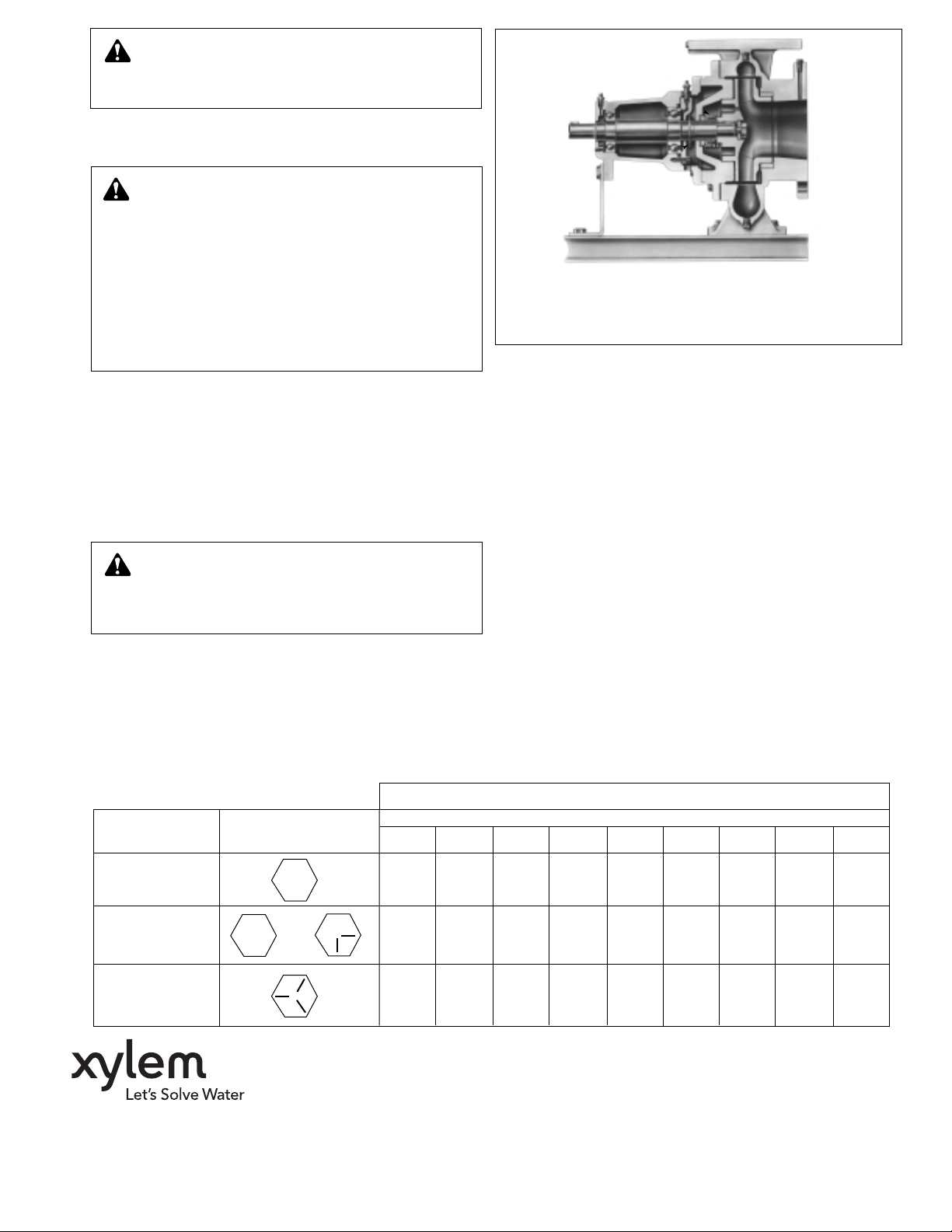
STANDARD MECHANICAL SEAL CONSTRUCTION
BASE-MOUNTED PUMP
NOTE: For additional information and instructions, refer to the
Installation Operation & Service Instructions Manual supplied with
your pump.
8. Remove the seal insert along with the insert gasket and
retainer (if used).
9. Thoroughly clean the shaft sleeve and the coverplate seal
cavity. Inspect for surface damage like pitting, corrosion,
nicks or scratches. Replace if necessary.
10. Lubricate the shaft sleeve and coverplate seal cavity with
soapy water. (Do not use petroleum lubricant.) Install a new
cup gasket and a new seal insert with indentation side down
into the cup.
11. Slide a new rotating seal assembly onto the shaft sleeve.
With a screwdriver push on the top of the compression ring
until the seal is tight against the seal insert. Install seal spring.
12. Install impeller, impeller washer, lock washer and capscrew,
then tighten capscrews (per torque chart).
13. Install new volute gasket then install pump assembly into
volute. Tighten volute capscrews (per torque chart). Install
seal flushing tube, if used. Install motor foot capscrews and
tighten. Install drain plug, close drain valve.
14. Open isolation valves, inspect pump for leaks, if not leaking
return pump to service.
CAPSCREW TORQUE (FOOT-POUND)
Capscrew Head
Type Marking
SAE Grade 2 6 13 25 38 60 120 190 210 300
Brass
Stainless Steel or
SAE Grade 5 10 20 35 60 90 180 325 525 800
Xylem Inc.
1
/4
4 10 17 27 42 83 130 200 300
5
/16
3
/8
Capscrew Diameter
7
/16
1
/2
5
/8
3
/4
7
/8 1
8200 N. Austin Avenue
Morton Grove, Illinois 60053
Phone: (847) 966-3700
Fax: (847) 965-8379
www.xyleminc.com/brands/bellgossett
Bell & Gossett is a trademark of Xylem Inc. or one of its subsidiaries.
© 2012 Xylem Inc. P71000B May 2012
 Loading...