

Page 1
~Bell
& Gossett
a
xylem
brand
INSTRUCTION MANUAL
P58671H
C@US
LISTED
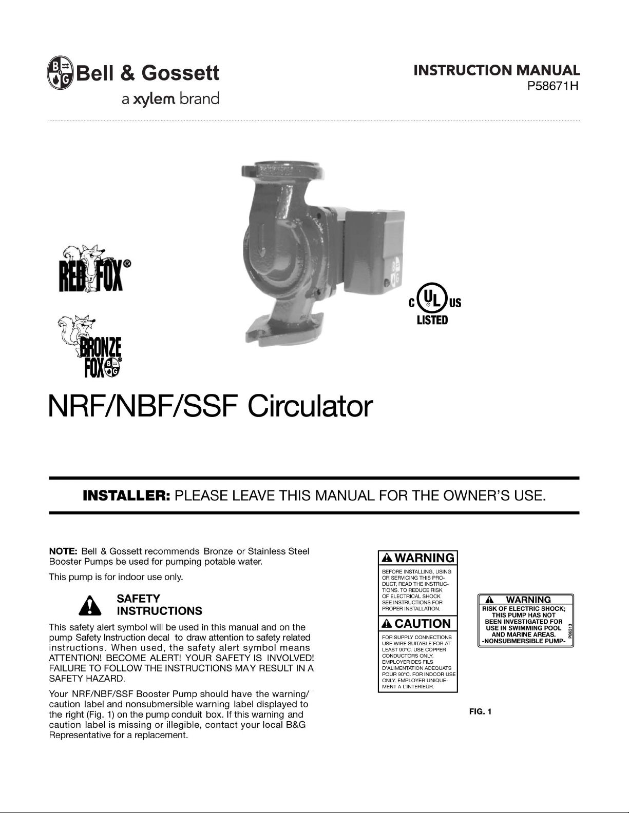
NRF/NBF/SSF
Circulator
INSTALLER: PLEASE LEAVE THIS MANUAL FOR THE OWNER'S USE.
NOTE: Bell & Gossett recommends Bronze or Stainless Steel
Booster Pumps be used for pumping potable water.
This pump is for indoor use
SAFETY
INSTRUCTIONS
This safety alert symbol will be used
Safety Instruction decal to draw attention to safety related
pump
instructions.
ATIENTION! BECOME ALERT! YOUR SAFETY
FAILURE
SAFETY HAZARD.
Your
NRF
caution
the right
caution
Representative for a
When
TO
FOLLOW
/NBF/SSF Booster Pump should have the warningl
label and nonsubmersible warning label displayed
(Fig.
1)
on the pump conduit box. If this warning and
label is missing
only.
used,
the
safety
THE
INSTRUCTIONS MA Y
or
illegible,
replacement.
in
this manual and on the
alert
symbol
means
IS
INVOLVED!
RESULT
contact
your local B&G
IN
to
A
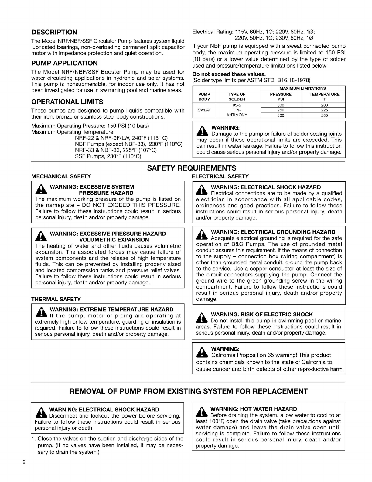
AWARNING
BEFORE INSTALLING , USING
OR SERVICING THIS PRO·
DUCT,
READ THE INSTRUC·
TIONS. TO REDUCE RISK
OF ELECTRI
CAL SHOCK
SEE INST
RUC
PROPER INSTALLATION.
TIONS FOR
A CAUTION
FOR SUPPLY CONNECTIONS
USE WI
RE
SUITABLE FOR
LEAST 90"C. USE COPPER
COND
UCTORS
EMPLOYER DES FILS
D'ALIMENTATION ADEQUATS
POUR
90
"C. FOR INDOOR USE
ONLY.
EMPLOYER UNIQUEMENT A L'INTERIEUR.
AT
ONLY.
A WARNING
RISK OF ELECTRIC SHOCK;
PUMP HAS NOT
THIS
BEEN INVESTIGATED
USE
IN
SWIMMING POOL g
AND MARINE AREAS.
-NONSUBMERSIBLE PUMP-
FIG. 1
FOR
~
Page 2
DESCRIPTION
The Model
lubricated
motor with impedance protection and quiet operation.
PUMP
The
water circulating applications
This
been investigated for use
NRF
/NBF/
SSF
Circulator Pump features system liquid
bearings, non-overloading permanent split capacitor
APPLICATION
Model
NRF/NBF/SSF
pump
is nonsubmersible, for indoor use only. It has not
Booster
in
swimming pool and marine areas.
Pump
may
in
hydronic and solar systems.
be used
OPERATIONAL LIMITS
These pumps are designed
their iron, bronze or
Maximum Operating Pressure: 150
Maximum Operating Temperature:
stainless steel
NRF-22 & NRF-9F/
NBF Pumps (except NBF-33), 230°F (110°
NRF-33 & NBF-33, 225°F
SSF Pumps, 230°F (110°
to
pump
liquids compatible with
body
constructions.
PSI
(10
bars)
LW
, 240°F (115°
(10rC)
C)
SAFETY REQUIREMENTS
MECHANICAL SAFETY
C)
Electrical Rating:
If your NBF pump
body
, the maximum operating pressure
(10 bars) or a lower value determined by the type
used and pressure/temperature limitations listed below:
for
Do
not
(Solder
exceed
type limits per ASTM STD. B16.18-1978)
PUMP
BODY
SWEAT
115V,
60Hz,
10;
220V, 60Hz,
220~50Hz,
is
equipped with a sweat connected pump
these
TYPE OF PRESSURE TEMPERATURE
SOLDER PSI
95-5 300 200
TIN-
A
NTI
MONY
values.
10;230~
60Hz,
is
MAXIMUM
250 225
200 250
WARNING:
C)
Damage to the pump
A
occur
may
can
result
could cause serious personal injury and/or property damage.
if these operational limits are exceeded. This
in
water leakage. Failure
or
failure
of
solder sealing joints
to
follow this instruction
ELECTRICAL SAFETY
10;
10
limited to 150
of
solder
LIMITATIONS
of
PSI
A WARNING: EXCESSIVE SYSTEM
..
The maximum working pressure
the
nameplate
Failure
personal injury, death and/
to
PRESSURE HAZARD
of
the
- DO
NOT
EXCEED
follow these instructions could result
or
property damage.
pump
THIS
PRESSURE.
is
listed on
in
serious
A WARNING: EXCESSIVE PRESSURE HAZARD
..
The heating
expansion. The
system
fluids. This can be prevented
and
Failure
personal injury, death and/
components
located compression tanks and pressure relief valves.
to
THERMAL SAFETY
VOLUMETRIC EXPANSION
of
wate
r and other fluids causes volumet ric
associated
and the release
follow these instructions could result
forces
or
property damage.
may
of
by
installing properly sized
cause failure
high temperature
in
serious
A WARNING: EXTREME TEMPERATURE HAZARD
..
If
the
pump, motor
extremely high or low temperature, guarding
required. Failure to follow these instructions could result
serious personal injury, death and/or property damage.
or
piping
are
operating
or
insulation
of
at
is
in
A WARNING: ELECTRICAL SHOCK HAZARD
..
Electrical connections are to be made by a qualified
electrician
ordinances
instructions could result in serious personal injury, death
and/or property damage.
in
accordance
and
good
with
practices.
all
applicable
Failure
to
follow
codes,
these
A WARNING: ELECTRICAL GROUNDING HAZARD
..
Adequate electrical grounding is required for the safe
operation
conduit assures this requirement. If the means of connection
to
the
other than grounded
to
the service. Use a copper conductor at least the size
the circuit
ground wire
compartment.
result in
damage.
of
B&G
Pumps.
supply -connection
metal conduit, ground the pump back
connectors
to
the green
Failure
serious
supplying the pump. Connect the
to
follow
personal
The
use
of
grounded
box
(wiring compartment) is
grounding
injury,
these
death
screw
instructions
and/
in
the
or
metal
of
wiring
could
property
A WARNING: RISK OF ELECTRIC SHOCK
..
Do not install this pump
areas.
Failure
serious personal injury, death and/or property damage.
to
follow these instructions could result
in
swimming pool
or
marine
in
A WARNING:
..
California Proposition 65 warning! This
contains chemicals
cause
cancer
known
and birth
to
the state
defects
of
other reproductive harm.
of
California
product
to
REMOVAL OF
PUMP
A WARNING: ELECTRICAL SHOCK HAZARD
..
Disconnect and lockout the power before servicing.
Failure to follow these instructions could result
personal injury
1.
Close the valves on the suction and discharge sides
pump.
sary to drain the system.)
2
or
death.
(If no valves have been installed, it may be neces-
FROM EXISTING SYSTEM FOR REPLACEMENT
A WARNING: HOT WATER HAZARD
..
Before draining the system, allow water
in
serious
of
the
least 100°F, open the drain valve (take precautions against
water
damage)
servicing is complete. Failure to follow these instructions
could
result
property damage.
and
in
serious
leave
personal
the
drain
valve
injury, death
to
cool to at
open
and/or
until
Page 3

A WARNING: ELECTRICAL SHOCK HAZARD
..
Be
certain the electric
motor
leads before
instructions could result
2. Loosen the conduit box cover screw and remove the cover.
3. Disconnect the
PUMP
INSTALLATION
A CAUTION:
..
It
is not advisable to install circulators
or upper
must
provide adequate drainage
to follow these instructions could result
floor over finished living space. If the circulator
be
installed over head, or over expensive equipment,
electrical supply lines to the pump.
PROPERTY
al
power
is
not present at the
continuing
in
. Failure
serious personal injury or death
DAMAGE
in
the event of leakage. Failure
to
follow
HAZARD
in
an
in
property damage.
these
attic
A WARNING: HIGH PRESSURE HAZARD
..
Pressure may be present in
pressure can be
shifting the pump
water to escape.
in
result
4. Remove the
1.
2.
3. Use 95-5 (Tin-Antimony); and a good grade
serious personal injury or death.
nuts. Then remove the pump from the piping.
Use a torch with a sharp pointed flame.
Clean tube ends and pump connections thoroughly.
relieved by loosening the flange bolts and
assembly slightly to allow the pressurized
Failure to follow these instructions could
flange nuts and bolts or loosen the union ring
the
pump
of
A CAUTION:
..
Heat associated with the use
damage a pump voiding the warranty.
solder. Failure
property damage and/or moderate personal injury.
to follow these instructions could result
of
silver solder may
Do
not use silver
body
flux.
. This
in
Locate the pump so there is sufficient room for inspection ,
maintenance and service.
installation
all
circulators
circulator without draining the system.
of
service valves on the suction and discharge
to
facilitate servicing
A CAUTION: The use
..
compound and
vides
lubricity which can lead to overtightening and break-
Do
age.
can
and/or property damage.
Install suction and discharge flanges or union connectors on
the pipe ends. The use
thread sealant is recommended.
Be
suction and discharge piping by the use
the pump. Line up the
bolt-holes
pipe
threads with union
THE SUCTION
MAY
FLANGE CONNECTIONS AND PIPING. The code for Pressure
Piping
various
Bell
NRF
pipe
screw and matching nut to connect the pump to the
not overtighten. Failure to follow this instruction
result in moderate personal injury from hot
sure to minimize any pipe-strain on the pump. Support the
in
the pump flanges match the bolt-holes
flanges. If union connections are used, line up the pump
tail pieces.
OR
DISCHARGE LINES
RESULT
(ANSI
& Gossett flange/union gaskets must
/NBF/
flanges/union tail pieces. Use 7
IN
UNWANTED STRESS
B31.1)
applications.
SSF
pump body flanges
lists many types of supports available for
Bell & Gossett recommends the
or
replacement
of
PTFE
of
vertical and horizontal piping so that the
PTFE impregnated pipe
tape on pipe threads pro-
PTFE
tape sealer
DO
NOT ATIEMPT
and
the suction and discharge
116
" diameter x 1
or
a high quality
of
pipe hangers near
IN
POSITION. THIS
IN
THE
PUMP BODY,
be
installed between the
TO
1
/2
" long cap
flanges.
of
the
water
in
the
SPRING
of
A CAUTION:
..
Excessive use
result
in
damage
excessive flux . Failure
in
result
4. When sweating the joints, first wrap the pump body with a
cool
subjecting the pump to excessive heat.
5.
Check
required, take care to avoid subjecting the pump to excessive heat.
property damage and/or moderate personal injury.
wet
rag,
soldered
of
solder
to
the
to
then
direct
connections
in
a vertical installation may
pump
impeller.
follow these instructions could
the
flame
for
leaks. If resoldering is
with
Do
care
not
to
use
avoid
A WARNING: WATER LEAKAGE HAZARD
..
To
prevent leakage, make certain that the flange bolts
or ring nuts have been adequately tightened and that the
solder
instructions
and/or property damage.
MODE
The Model
charge up or down,
shaft must remain
body must point
must be positioned on the
housing (see figure 2). If the conduit box position must be
changed, it is best to
pump is
PUMP
before proceeding.
connections
could result
do
not
leak. Failure
in
serious personal injury, death
to
follow these
OF DISCHARGE
NRF
/NBF/SSF Circulator can be installed to dis-
horizontally, left or right, but the motor
in
the horizontal position, the arrow on the
in
the direction
do
so before installation. However, if the
already installed, see the section titled "REMOVAL
FROM EXISTING SYSTEM FOR REPLACEMENT"
top
of
the flow, the conduit box
or
to
the side
of
the
motor
OF
A WARNING: HOT WATER HAZARD
..
When disassembling a gasketed joint, always use a
new
gasket
GASKETS. Failure to follow these instructions could result
in
serious personal injury, death and/or property damage.
upon
reassembly
. NEVER RE-USE
OLD
A WARNING: HOT WATER HAZARD
..
Make sure that each flange gasket remains seated
the flange groove during and after installation. Failure to
follow these instructions could result
injury, death and/or property damage.
Apply torque
value
of
flange bolts must be torqued
If your NBF pump is equipped with a sweat connected pump
body, see the
in
115 in-Ibs. is reached. Both the suction and discharge
even increments
in
this manner.
following instructions:
in
serious personal
to
both flange bolts until a
in
A CAUTION:
..
Make sure the
anything inside the discharge opening to move the impeller.
power
is turned
off
before placing
TO CHANGE THE CONDUIT POSITION
1. Remove the four
supporting the motor assembly.
2. Remove
rotate it to the desired position
3. Replace the Allen screws and tighten evenly
method to 60 in-Ibs.
4.
Check to see that the impeller turns freely. Insert your finger
in
pump body points
you can feel the impeller and rotate it with your fingertip. If
the impeller does not turn easily, repeat the disassembly/
reassembly
the
the discharge port of the pump body (the arrow on the
(4)
motor
process.
1/4-20
Allen screws (3
assembly
in
the direction
from
(see
11
6 wrench) while
the
pump
body
figure
2).
in
a diagonal
of
the discharge) until
and
3
Page 4

WARNING: ELECTRICAL SHOCK HAZARD
FIG. 2
Disconnect and lock out the power befor e making
electrical connections. Failur e
to follow these instructions
could result in serious personal injury or death.
WIRING INSTRUCTIONS
A. Loosen the scr ew securing the conduit box cover (wiring
compartment), and remove the screw & cover.
B. Attach the appropriate size connector to the hole in the side
of the conduit box.
C. Using a minimum size of 14 AWG copper electrical wire
(refer to your local code for wiring restrictions), wire the
motor to a single phase power sour ce that matches the
electrical rating on the pump nameplate. See Fig. 3. Use
the size of electrical wire as dictated by local code.
D. Connect the ground wire to the inside of the conduit box
with one of the gr een screws provided inside the box. See
Fig. 4.
NOTE: Electrical supply and grounding wires must be suitable for at least 90°C (194°F).
NOTE: Model NRF/NBF/SSF Cir culators are impedance
protected and do not r
equire external overload protection.
WARNING: ELECTRICAL SHOCK HAZARD
Be certain that all connections ar e secure and the
conduit box cover is closed befor e
electrical power is
connected. Failure to follow these instructions could r esult
in serious personal injury, death and/or property damage.
TYPICAL WIRING INSTALLATION SCHEMA
1Ø POWER SOURCE
FUSIBLE DISCONNECT
OR CIRCUIT BREAKER BY
OTHERS
TIC
S
TO REMOTE
CONTROL
IF REQUIRED
LN
PUMP
MOTOR
PUMP MOTOR
IMPEDANCE
PROTECTED
FIG. 3
CONDUIT BOX WIRING
ALTERNATE
SCREW
FIG. 4
LINE
LEADS
SYSTEM PREPARA
GROUND
TION
Prior to pump start-up, closed heating and cooling systems
should be cleaned,
drained, and refilled with clean water. The
system fluid pH must be maintained between 7 and 9.
START-UP
Do
start
not
Air should be vented fr om the system by means of an air vent
located at a high point in the system. The system must be
completely vented prior to pump operation. Do not run NRF/
NBF/SSF circulators dry. Pump operation without water cir culation could result in pump and motor damage.
pump until the system has been filled and vented.
DETAIL
GREEN
GROUND
SCREW
WARNING: HOT WATER LEAKAGE HAZARD
Pressurize the body slowly while checking for leaks at
all joints with gaskets or solder connections. Failur e to follow
these instructions could r esult in serious personal injury
and/or property damage.
PERIODIC INSPECTION
Bell & Gossett NRF/NBF/SSF Cir culators are designed to
provide
periodic inspections be made to check for potential pr oblems
with the pump. If any leakage or evidence of leakage is pr esent, repair or replace the unit.
years of trouble free service. It is recommended that
Xylem Inc.
8200 N. Austin Avenue
Morton Grove, Illinois 60053
Phone: (847) 966-3700
Fax: (847) 965-8379
www.xyleminc.com/brands/bellgossett
Bell & Gossett is a trademark of Xylem Inc. or one of its subsidiaries.
© 2013 Xylem Inc. P58671H January 2013
 Loading...