

Page 1
INSTRUCTION MANUAL
Integrated Technologic
with Sensorless Control
®
Page 2

Page 3

Table of Contents
Introduction and Safety..................................................................................................................2
Introduction..................................................................................................................................2
Safety.............................................................................................................................................2
Safety message levels............................................................................................................. 2
User safety.................................................................................................................................... 3
Environmental safety...................................................................................................................4
Transportation and Storage.......................................................................................................... 6
Inspect the delivery.....................................................................................................................6
Inspect the package................................................................................................................6
Inspect the unit........................................................................................................................ 6
System lifting................................................................................................................................6
Transportation guidelines.......................................................................................................... 6
Storage guidelines...................................................................................................................... 6
Product Description........................................................................................................................8
System description......................................................................................................................8
Table of Contents
Electrical Installation.................................................................................................................... 10
Preinstallation............................................................................................................................ 10
Line input (mains) connection................................................................................................. 11
Control terminal connections.................................................................................................. 12
Control terminal configurations.............................................................................................. 15
Common terminal wiring configurations............................................................................... 16
Local control panel....................................................................................................................22
Menu keys.................................................................................................................................. 23
Navigation keys......................................................................................................................... 23
Operation keys.......................................................................................................................... 24
Programming the controller.................................................................................................... 25
System Setup and Operation......................................................................................................27
Pre-start procedure...................................................................................................................27
Pre-startup inspections.............................................................................................................28
Start-up procedure....................................................................................................................28
Setup and commissioning....................................................................................................... 29
Troubleshooting........................................................................................................................... 38
Troubleshooting menus...........................................................................................................38
Reset the frequency converter................................................................................................ 38
Warnings and alarms................................................................................................................41
Integrated Technologic® with Sensorless Control INSTRUCTION MANUAL 1
Page 4

Introduction and Safety
Introduction and Safety
Introduction
Purpose of this manual
The purpose of this manual is to provide necessary information for:
• Installation
• Operation
• Maintenance
CAUTION:
Read this manual carefully before installing and using the product. Improper use of the
product can cause personal injury and damage to property, and may void the warranty.
NOTICE:
Save this manual for future reference, and keep it readily available at the location of the
unit.
Safety
WARNING:
• The operator must be aware of safety precautions to prevent physical injury.
• Any pressure-containing device can explode, rupture, or discharge its contents if it is
over-pressurized. Take all necessary measures to avoid over-pressurization.
• Operating, installing, or maintaining the unit in any way that is not covered in this
manual could cause death, serious personal injury, or damage to the equipment. This
includes any modification to the equipment or use of parts not provided by Xylem. If
there is a question regarding the intended use of the equipment, please contact a
Xylem representative before proceeding.
• Do not change the service application without the approval of an authorized Xylem
representative.
CAUTION:
You must observe the instructions contained in this manual. Failure to do so could result
in physical injury, damage, or delays.
Safety message levels
About safety messages
It is extremely important that you read, understand, and follow the safety messages and
regulations carefully before handling the product. They are published to help prevent
these hazards:
• Personal accidents and health problems
• Damage to the product
• Product malfunction
2 Integrated Technologic® with Sensorless Control INSTRUCTION MANUAL
Page 5
Definitions
Safety message level Indication
DANGER:
A hazardous situation which, if not avoided, will result in
death or serious injury
Introduction and Safety
User safety
General safety rules
WARNING:
CAUTION:
Electrical Hazard:
NOTICE:
These safety rules apply:
• Always keep the work area clean.
• Pay attention to the risks presented by gas and vapors in the work area.
• Avoid all electrical dangers. Pay attention to the risks of electric shock or arc
hazards.
• Always bear in mind the risk of drowning, electrical accidents, and burn injuries.
A hazardous situation which, if not avoided, could result
in death or serious injury
A hazardous situation which, if not avoided, could result
in minor or moderate injury
The possibility of electrical risks if instructions are not
followed in a proper manner
• A potential situation which, if not avoided, could
result in undesirable conditions
• A practice not related to personal injury
flash
Safety equipment
Use safety equipment according to the company regulations. Use this safety equipment
within the work area:
• Hard hat
• Safety goggles, preferably with side shields
• Protective shoes
• Protective gloves
• Gas mask
• Hearing protection
• First-aid kit
• Safety devices
NOTICE:
Never operate a unit unless safety devices are installed. Also see specific information
about safety devices in other chapters of this manual.
Integrated Technologic® with Sensorless Control INSTRUCTION MANUAL 3
Page 6

Introduction and Safety
Electrical connections
Electrical connections must be made by certified electricians in compliance with all
international, national, state, and local regulations. For more information about
requirements, see sections dealing specifically with electrical connections.
Precautions before work
Observe these safety precautions before you work with the product or are in connection
with the product:
• Provide a suitable barrier around the work area, for example, a guard rail.
• Make sure that all safety guards are in place and secure.
• Make sure that you have a clear path of retreat.
• Make sure that the product cannot roll or fall over and injure people or damage
• Make sure that the lifting equipment is in good condition.
• Use a lifting harness, a safety line, and a breathing device as required.
• Allow all system and pump components to cool before you handle them.
• Make sure that the product has been thoroughly cleaned.
• Disconnect and lock out power before you service the pump.
• Check the explosion risk before you weld or use electric hand tools.
Precautions during work
property.
Observe these safety precautions when you work with the product or are in connection
with the product:
Wash the skin and eyes
• Never work alone.
• Always wear protective clothing and hand protection.
• Stay clear of suspended loads.
• Always lift the product by its lifting device.
• Beware of the risk of a sudden start if the product is used with an automatic level
control.
• Beware of the starting jerk, which can be powerful.
• Rinse the components in water after you disassemble the pump.
• Do not exceed the maximum working pressure of the pump.
• Do not open any vent or drain valve or remove any plugs while the system is
pressurized. Make sure that the pump is isolated from the system and that pressure is
relieved before you disassemble the pump, remove plugs, or disconnect piping.
• Never operate a pump without a properly installed coupling guard.
Follow these procedures for chemicals or hazardous fluids that have come into
contact with your eyes or your skin:
Condition Action
Chemicals or hazardous fluids in
eyes
Chemicals or hazardous fluids on
skin
1. Hold your eyelids apart forcibly with your fingers.
2. Rinse the eyes with eyewash or running water for at least 15 minutes.
3. Seek medical attention.
1. Remove contaminated clothing.
2. Wash the skin with soap and water for at least 1 minute.
3. Seek medical attention, if necessary.
Environmental safety
The work area
Always keep the station clean.
4 Integrated Technologic® with Sensorless Control INSTRUCTION MANUAL
Page 7

Waste and emissions regulations
Observe these safety regulations regarding waste and emissions:
• Appropriately dispose of all waste.
• Handle and dispose of the processed liquid in compliance with applicable
environmental regulations.
• Clean up all spills in accordance with safety and environmental procedures.
• Report all environmental emissions to the appropriate authorities.
WARNING:
Radiation Hazard. Do NOT send the product to Xylem if it has been exposed to any
nuclear radiation.
Electrical installation
For electrical installation recycling requirements, consult your local electric utility.
Recycling guidelines
Always follow local laws and regulations regarding recycling.
Introduction and Safety
Integrated Technologic® with Sensorless Control INSTRUCTION MANUAL 5
Page 8

Transportation and Storage
Transportation and Storage
Inspect the delivery
Inspect the package
1. Inspect the package for damaged or missing items upon delivery.
2. Note any damaged or missing items on the receipt and freight bill.
3. File a claim with the shipping company if anything is out of order.
If the product has been picked up at a distributor, make a claim directly to the
distributor.
Inspect the unit
1. Remove packing materials from the product.
Dispose of all packing materials in accordance with local regulations.
2. Inspect the product to determine if any parts have been damaged or are missing.
3. If applicable, unfasten the product by removing any screws, bolts, or straps.
For your personal safety, be careful when you handle nails and straps.
4. Contact the local sales representative if there is any issue.
System lifting
WARNING:
• Assembled units and their components are heavy. Failure to properly lift and support
this equipment can result in serious physical injury and/or equipment damage. Lift
equipment only at the specifically identified lifting points. Lifting devices such as
eyebolts, slings, and spreaders must be rated, selected, and used for the entire load
being lifted.
• Crush hazard. The unit and the components can be heavy. Use proper lifting methods
and wear steel-toed shoes at all times.
Transportation guidelines
Precautions
DANGER:
Disconnect and lock out electrical power before installing or servicing the unit.
WARNING:
• Stay clear of suspended loads.
• Observe accident prevention regulations in force.
Storage guidelines
Storage location
The product must be stored in a covered and dry location free from heat, dirt, and
vibrations.
6 Integrated Technologic® with Sensorless Control INSTRUCTION MANUAL
Page 9

Transportation and Storage
NOTICE:
• Protect the product against humidity, heat sources, and mechanical damage.
• Do not place heavy weights on the packed product.
Integrated Technologic® with Sensorless Control INSTRUCTION MANUAL 7
Page 10

Product Description
Product Description
System description
The Technologic Sensorless Pump Controller is a variable frequency drive that has been
configured for pump control applications. The controller utilizes four different setups to
allow the user to easily setup the controller for 4 different applications.
Set-up 1 Constant pressure control with wire pressure transducer. The controller setpoint
is preconfigured at 15 psi. The analog input AI53 is configured for a 40 psi
pressure transducer.
Set-up 2 Flow control with wired flow transducer. The controller setpoint is preconfigured
at 150 GPM. The analog input AI53 is configured for a 300 GPM flow transducer.
Set-up 3 Sensorless pressure control The controller setpoint is preconfigured at the
factory based on the order request.
Set-up 4 Sensorless flow control. The controller setpoint is preconfigured at the factory
based on the order request.
• Set-up 3 is the active set-up for the factory default configuration.
Enclosure rating
Ambient temperature
WARNING:
The enclosure rating of the controller must be maintained by using the appropriate wire
or conduit connectors and installing the controller in the appropriate environment. Failure
to use the appropriate connectors or to install in the appropriate environment may create
a dangerous condition and will void the warranty.
• The standard enclosure rating for the controller is IP55 or NEMA12.
• The controller is intended for indoor use only.
• Ensure the installation environment complies with the controller rating.
• Make sure all cable glands and unused holes for glands are properly sealed and the
cover is properly installed.
• Ensure that the system is installed in an environment that complies with the motor
ingress protection rating. Refer to the motor IOM manual for details.
WARNING:
The ambient temperature rating of the controller must be maintained by installing the
controller in the appropriate environment. Failure to operate the controller in the
appropriate environment may create a dangerous condition and will void the warranty.
• To ensure proper cooling of the controller, there must be adequate space above and
below the controller chassis. Refer to the Technologic Pump Controller IOM for
details.
• The controller can be operated with full load output current at maximum ambient
temperature up to the maximum altitude of 1000 m above sea level. For altitudes
above 1000 m, the maximum output current and/or maximum ambient temperature
must be derated. Refer to the Technologic Pump Controller IOM for details. Contact
the factory for installation above 2000 m.
Maximum Temperature Minimum Temperature
113°F (45°C) 32°F (0°C)
8 Integrated Technologic® with Sensorless Control INSTRUCTION MANUAL
Page 11

Maximum Temperature Minimum Temperature
The output current rating is derated 2% for every degree
above 113°F(45°C).
The controller will operate with reduced performance
down to 14°F (-10°C)
At 122°F (50°C), the maximum output current rating of
the controller will be reduced by 10%.
Product Description
Integrated Technologic® with Sensorless Control INSTRUCTION MANUAL 9
Page 12
Electrical Installation
Electrical Installation
Preinstallation
Precautions
Electrical Hazard:
• Branch circuit protection required. Provide branch circuit protection in accordance
with the National Electrical Code.
• Motor control equipment and electronic controls are connected to hazardous line
voltages. Extreme care should be taken to protect against electrical hazard.
• Proper protective grounding of the equipment must be established. Ground currents
are higher than 3 mA.
• A dedicated ground wire is required.
WARNING:
• Rotating shafts and electrical equipment can be hazardous. It is strongly
recommended that all electrical work conform to all National and Local regulations.
Installation, Start-up, and Maintenance should be performed only by qualified
personnel.
• Wear safety glasses whenever working on electric control or rotating equipment.
NOTICE:
Make all power connections with minimum 75°C rated copper wiring for installations in
North America.
10 Integrated Technologic® with Sensorless Control INSTRUCTION MANUAL
Page 13
*
91 (L1)
92 (L2)
93 (L3)
PE
88 (-)
89 (+)
50 (+10 V OUT)
53 (A IN)
54 (A IN)
55 (COM A IN)
0/4-20 mA
12 (+24V OUT)
13 (+24V OUT)
18 (D IN)
20 (COM D IN)
15mA 200mA
(U) 96
(V) 97
(W) 98
(PE) 99
(COM A OUT) 39
(A OUT) 42
0/4-20 mA
03
0-10Vdc
+10Vdc
0-10Vdc
0/4-20 mA
240Vac, 2A
24Vdc
02
01
05
04
06
240Vac, 2A
24V (NPN)
0V (PNP)
0V (PNP)
24V (NPN)
19 (D IN)
24V (NPN)
0V (PNP)
27
24V
0V
(D IN/OUT)
0V (PNP)
24V (NPN)
(D IN/OUT)
0V
24V
29
24V (NPN)
0V (PNP)
0V (PNP)
24V (NPN)
33 (D IN)
32 (D IN)
1 2
ON
A53/S201
ON
21
A54/S202
ON=0-20mA
OFF=0-10V
95
400Vac, 2A
P 5-00
(R+) 82
(R-) 81
37 (D IN)
+ - + -
130BA544.12
(P RS-485) 68
(N RS-485) 69
(COM RS-485) 61
0V
5V
S801
RS-485
RS-485
21
ON
BUS TER./S801
3 Phase
power
input
DC bus
Switch Mode
Power Supply
Motor
Analog Output
Interface
relay1
relay2
ON=Terminated
OFF=Open
Brake
resistor
(NPN) = Sink
(PNP) = Source
Electrical Installation
Fuses
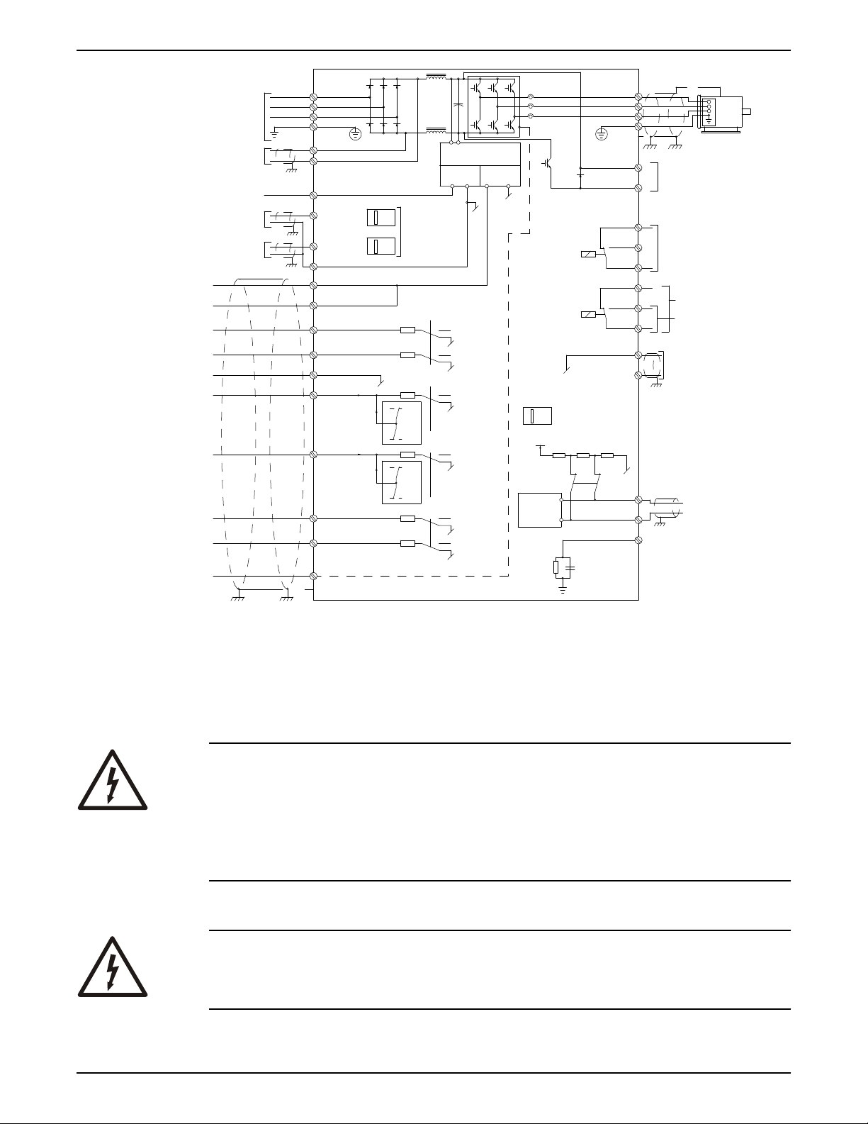
Figure 1: Basic wiring schematic drawing
For models with an optional fused disconnect installed, input fuses have been factory
installed in the enclosure. For models without a fused disconnect option, appropriate fuse
protection must be provided by the installer. Refer to the Technologic Pump Controller
IOM for a list of appropriate fuses for each model.
Electrical Hazard:
• Replacement fuses must be of the same continuous rating, fuse type and have the
Line input (mains) connection
Integrated Technologic® with Sensorless Control INSTRUCTION MANUAL 11
same maximum interrupting rating as the fuse being replaced.
• Before replacing a blown fuse or resetting a circuit breaker, the source of the fault
causing the fuse to blow must be found and remedied.
• Before connecting the input power wiring or fusing, ensure all input disconnects or
breakers are set and locked to the off position.
Electrical Hazard:
For operator’s safety, it is important to ground drive properly. Failure to ground drive
properly could result in death or serious injury.
Page 14
130BT334.10
Electrical Installation
NOTICE:
It is the responsibility of the user or certified electrical installer to ensure correct
grounding (earthing) of the equipment in accordance with national and local electrical
codes and standards.
Requirements:
• Follow all local and national codes for proper electrical equipment grounding
(earthing).
• Proper protective grounding of the equipment must be established. Ground currents
are higher the 3 mA.
• A dedicated ground wire is required.
• Do not use conduit as a replacement for a ground wire.
• Do not ground one controller to another in a “daisy chain” fashion. Each controller
must have a dedicated ground connection.
• A high strand count ground wire is preferred for dissipating high frequency electrical
noise.
• Keep the ground wire connections as short as possible.
1. Ensure the input power source for the controller is locked in the off position.
2. Connect metalized conduit to the controller.
3. Route the power wiring through the conduit.
4. Connect the input power wires to terminals labeled L1, L2, L3 and (Ground) on the
input side of the disconnect.
Refer to the Technologic Pump Controller IOM for details on wire sizing and routing.
Control terminal connections
Make sure that the following are adhered to:
• Run input power and control wiring in separate metallic conduits or raceways for high
frequency isolation. Failure to isolate power, motor, and control wiring could result in
less than optimum drive and associated equipment performance.
• Use control wiring rated for 600 V for 480 V and 600 V drives and 300 V for 200–240 V
drives.
• Make sure to isolate the control wiring from high-power components in the drive.
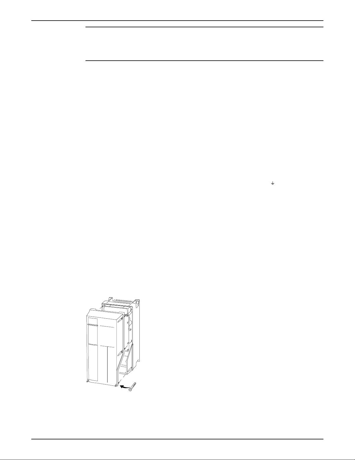
Control wiring access
• Remove front cover of unit to access internally mounted control terminals.
Figure 2: Control terminals access
12 Integrated Technologic® with Sensorless Control INSTRUCTION MANUAL
Page 15
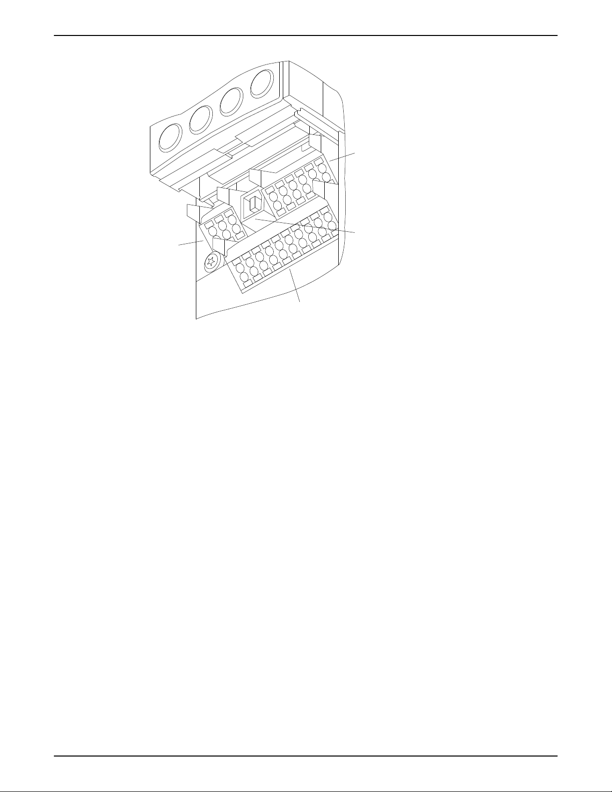
Removable control terminal connectors
1
4
2
3
130BA012.12
61
68
69
39
42
50
53
54
55
12
13
18
19
27
29
32
33
20
Electrical Installation
Figure 3: Drive control terminals
Connector 1
Connector 2 For serial communications EIA-485 connector with terminal 68 (+) and 69
Connector 3 Analog Input and Output Terminals
Connector 4 A USB port available for use with the MCT-10 drive programming
Relay Terminals Also provided are two Form C relay outputs that are in various locations
Connecting to the control terminals
1. To connect control wiring to the control terminals, do the following:
2. To remove the wire from the terminal:
Digital Input and Output terminals
• Four programmable digital outputs
• Two digital terminals programmable as input or output
• A common for optional customer supplied 24 VDC voltage
• A 24 VDC supply used for digital inputs and external transducers.
(-).
• Two analog inputs configurable as current or voltage inputs
• One analog output
• A 10 VDC supply for voltage output transducers
• A common for analog inputs and outputs
software.
depending upon the controller configuration and size.
a. Strip the control wire back 9–10mm (0.35–0.40 in)
b. Insert a screwdriver (0.4 x 2.5 mm) in the rectangular hole.
c. Insert the cable in the adjacent circular hole.
d. Remove the screwdriver. The wire is now mounted to the terminal.
a. Insert a screwdriver (0.4 x 2.5 mm) in the rectangular hole.
b. Pull out the cable.
Integrated Technologic® with Sensorless Control INSTRUCTION MANUAL 13
Page 16
130BA150.10
9 - 10 mm
(0.37 in)
130BT311.10
130BT312.10
1. 2. 3.
130BT310.10
Electrical Installation
Figure 4: Connecting and disconnecting control wiring
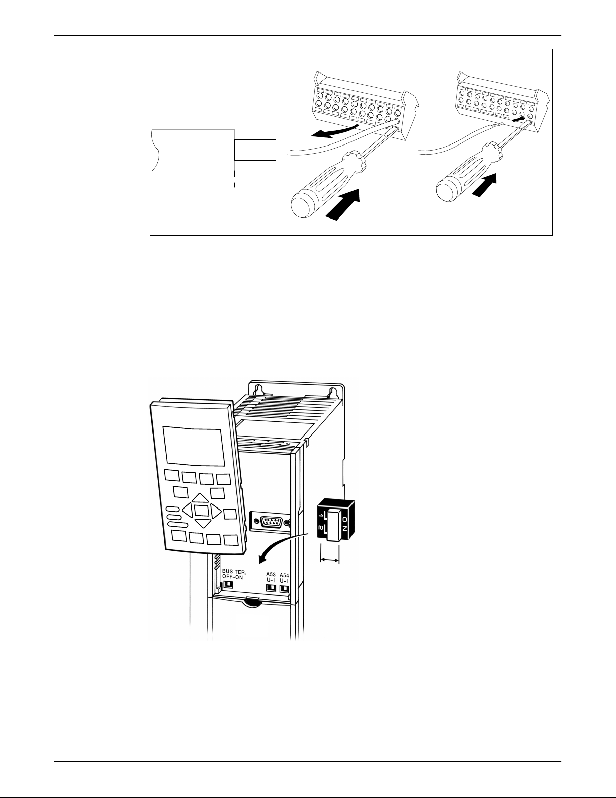
Analog input configuration
If an analog input is used, the analog input configuration switches must be set properly.
To set the configuration switches, remove the local control panel and set the appropriate
switch as required.
• To configure the analog input as a voltage input, set the configuration switch to U.
• Set the configuration switch to I to enable the input as a current input.
• Switch A53 is used to configure analog input 53.
• Switch A54 is used to configure analog input 54.
Figure 5: Configuration switch location
14 Integrated Technologic® with Sensorless Control INSTRUCTION MANUAL
Page 17

Electrical Installation
Control terminal configurations
Table 1: Control terminal descriptions
Terminal number Parameter Default setting Description
Relay Outputs 01, 02, 03 5-40 Relay1 [160] No Alarm Form C Relay Output.
04, 05, 06 5-40 Relay2 [5] Running
Digital I/O 12, 13 - +24 V DC 24 V DC supply voltage.
18 5-10 [8] Start Start/Stop digital input
19 5-11 [0] No Operation Unused digital input
27 5-12 [0] No Operation Unused digital input
29 5-13 [0] No Operation Unused digital input
32 5-14 [0] No Operation Unused digital input
33 5-15 [0] No Operation Unused digital input
20 - Common Common for digital inputs
Analog I/O 39 - AO Common Common for analog output
42 6-50 4-20mA Motor Freq Analog output. Default
50 - +10 V DC 10 V DC analog supply
53 6-1 [0] No Operation Analog input 53.
54 6-2 [0] No Operation Analog input 54.
55 - AI Common Common for analog input
Common 61 - Shield Connection Integrated RC filter for
68 8-3 + RS485 Interface +
69 8-3 - RS485 Interface -
Usable for AC or DC
voltages and either
resistive or inductive loads.
Refer to the relay wiring
section for relay contact
current and voltage ratings.
Maximum output current is
200 mA total for all 24 V
loads. Useable for digital
inputs and external
transducers.
signal for the drive.
Connect input to 24 V to
start. Open the input to
stop.
and reference for 24 V
supply
setting is 4-20mA signal
(500 Ω max) based on
motor speed
voltage. 15mA maximum.
cable shield. ONLY for
connecting the shield
when experiencing EMC
problems.
Refer to the Technologic Controller IOM for details on control terminal wiring.
Integrated Technologic® with Sensorless Control INSTRUCTION MANUAL 15
Page 18

Electrical Installation
Common terminal wiring configurations
Relay wiring
Each controller has two programmable form C relay outputs. The relay terminals are
located in various locations on the controller depending on the frame size.
Figure 6: Relay terminal wiring
Table 2: Relay terminal ratings
Programmable relay outputs 2
Relay 01 Terminal number 1–3 (break), 1–2 (make)
Maximum terminal load (AC-1)1 on 1–3 (NC), 1–2 (NO) (Resistive load) 240 V AC, 2A
Maximum terminal load (AC-15)1 (Inductive load @ cosφ 0.4) 240 V AC, 0.2A
Maximum terminal load (DC-1)1 on 1–2 (NO), 1–3 (NC) (Resistive load) 60 V DC, 1A
Maximum terminal load (DC-13)1 (Inductive load) 24 V DC, 0.1A
Relay 02 Terminal number 4–6 (break), 4–5 (make)
Maximum terminal load (AC-2)1 on 4–5 (NO) (resistive load)
Maximum terminal load (AC-15)1 (Inductive load @ cosφ 0.4) 240 V AC, 0.2A
Maximum terminal load (DC-1)1 on 4–5 (NO) (Resistive load) 80 V DC, 2A
Maximum terminal load (DC-13)1 on 4–5 (NO) (Inductive load) 24 V DC, 0.1A
Maximum terminal load (AC-1)1 on 4–6 (NC) (Resistive load) 240 V AC, 2A
Maximum terminal load (AC-15)1 on 4–6 (NC) (Inductive load @ cosφ
0.4)
Maximum terminal load (DC-1)1 on 4–6 (NC) (Resistive load) 50 V DC, 2A
Maximum terminal load (DC-13)1 on 4–6 (NC) (Inductive load) 24 V DC, 0.1A
Minimum terminal load on 1–3 (NC), 1–2 (NO), 4–6 (NC), 4–5 (NO) 24 V DC 10mA, 24 V AC 20mA
Environment according to EN 60664–1 overvoltage category III/pollution degree 2
2,3
400 V AC, 2A
240 V AC, 0.2A
Factory default setup
configuration utilizes the controller factory default settings for I/O. The factory default
This
settings are configured for Set-up 3, sensorless pressure control with no external
transducer installed. There are no parameters that need to be adjusted to use this
configuration. Set-up 4, sensorless flow control, also uses these default settings for I/O.
Set-ups are changed by adjusting parameter 0-10 Active Set-up. Refer to the
Commissioning section in this manual for details on changing set-ups.
NOTICE:
The factory default settings are configured to require a start signal wired to DI18 as shown
below.
16 Integrated Technologic® with Sensorless Control INSTRUCTION MANUAL
Page 19

Figure 7: Terminal connections when using factory defaults
Adding an external interlock
This setup adds an external interlock signal to the factory default configuration. An
external interlock can be used in applications that operate at extreme temperatures
and/or pressures to turn off the controller and issue an alarm during an abnormal system
condition. The external interlock signal is connected to digital input 27 on the controller.
This input can be controlled by an external device such as a suction pressure switch, an
over pressure switch, temperature switch, a differential pressure switch, etc. When the
input is disconnected from the 24V supply, an alarm is issued and the controller stops the
motor. The controller will attempt to automatically restart if the Reset Mode [14-20] and
Automatic Restart Time [14-21] are set to allow automatic restarting. To prevent an
automatic restart set the Reset Mode [14-20] to Manual Reset.
Electrical Installation
Figure 8: Terminal connections for external interlock
Table 3: Parameter settings for using an external interlock
Parameter number Description Set to
5–12 Terminal 27 Digital Input External Interlock
14–20 Reset Mode Set to the desired number of
14–21 Automatic Restart Time This is the time between when an
Adding transducer feedback
This configuration adds a transducer for closed loop control or for external monitoring.
Use Set-up 1 for pressure control using a wired pressure transducer and Set-up 2 for flow
control using a wired flow transducer. Refer to the Commissioning section in this manual
for detail on changing set-ups.
automatic resets. If a fault occurs
more than this setting a manual reset
is required. Set to Manual Reset if no
resets are allowed. Default setting is:
Automatic reset x 3.
alarming/warning is issued and when
the controller attempts the next
restart. Default setting is 30 seconds.
Integrated Technologic® with Sensorless Control INSTRUCTION MANUAL 17
Page 20

Electrical Installation
NOTICE:
Be sure to properly set the analog input configuration switches prior to using the analog
input.
Figure 9: Terminal connections for 4–20mA wired sensor
Figure 10: Terminal connections for 0–10V wired sensor
In order to set up the controller for closed loop control based on the feedback from an
external transducer, set the following parameters:
Table 4: Parameter settings for using a wired sensor for feedback
Parameter number Description Set to
0–10 Active Set-up For wired pressure transducer select
Set-up 1. For wired flow transducer
select Set-up 2.
6-14* Terminal 53 Low Ref./Feedb. Value Minimum transducer feedback value.
For example, for a 0–40 psi DP
transducer, set to 0.
6-15* Terminal 53 High Ref./Feedb. Value Maximum transducer feedback value.
For example, for a 0–40 psi DP
transducer, set to 40.
6-17* Terminal 53 Live Zero Enabled
20-00 Feedback 1 Source Analog Input 53*
20-12 Reference/Feedback Select as appropriate for application.
For example, set to psi when using a
pressure transducer.
20–13 Minimum Reference/Feedback Minimum transducer feedback value.
For example, for a 0–40 psi DP
transducer, set to 0 psi.
20–14 Maximum Reference/Feedback Maximum trnasducer feedback value.
For example, for a 40 psi DP
transducer, set to 40 psi.
18 Integrated Technologic® with Sensorless Control INSTRUCTION MANUAL
Page 21

Electrical Installation
* To use AI 54, configure parameters 6–24, 6–25, 6–27 and set 20–00 to Analog Input 54.
In order to set up the controller with a transducer that is used for external monitoring,
rather than feedback to the controller, set the following parameters:
Table 5: Parameter settings for using a wired sensor for external monitoring
Parameter number Description Set to
0-24 Display Line 3 Large Ext. 1 Feedback [Unit]
21-14 Ext. 1 Feedback Source Analog Input 53*
21–10 Ext. 1 Ref./Feedback Unit Select as appropriate for application.
For example, set to psi when using a
pressure transducer.
21–11 Ext. 1 Minimum Reference Minimum transducer feedback value.
For example, for a 0–40 psi DP
transducer, set to 0 psi.
21–12 Ext. 1 Maximum Reference Maximum transducer feedback value.
For example, for a 40 psi DP
transducer, set to 40 psi.
6–14* Terminal 53 Low Ref./Feedb. Value Minimum transducer feedback value.
For example, for a 0–40 psi DP
transducer, set to 0 psi.
6–15* Terminal 53 High Ref./Feedb. Value Maximum transducer feedback value.
For example, for a 40 psi DP
transducer, set to 40 psi.
6–17* Terminal 53 Live Zero Disabled
* To use AI 54, configure parameters 6–24, 6–25, 6–27 and set 21–14 to Analog Input 54.
Speed control with external potentiometer
This setup allows the speed of the motor to be controlled via an external potentiometer.
In order to use this setup the analog input must be configured as a voltage input.
Figure 11: Terminal connections for external speed reference from a potentiometer
To set up the controller for speed control with an external potentiometer, set the
following parameters:
Parameter number Description Set to
1-00 Configuration Mode Open Loop
3-15 Reference 1 Source Analog Input 53
6-10 Terminal 53 Low Voltage* 0 V
6-11 Terminal 53 High Voltage* 10 V
6-14 Terminal 53 Low Ref./Feedb. Value 0
Integrated Technologic® with Sensorless Control INSTRUCTION MANUAL 19
Page 22

Electrical Installation
Parameter number Description Set to
6-15 Terminal 53 High Ref./Feedb. Value Maximum motor speed. For example,
6-17 Terminal 53 Live Zero Disabled.
20-00 Feedback 1 Source No Function
* Set switch A53 = U
Control from external PLC/BMS through Analog Input
This setup allows the controller to receive either the process variable, the setpoint or a
speed reference from an external control source such as a PLC or BMS controller. The
output from the external control device can be either a voltage or current output signal.
Be sure to set the analog input configuration switches based on the type of output signal.
The diagram below shows the connections for an external reference signal.
3450 Hz.
Figure 12: Terminals connections for external control source
Table 6: Parameter settings for using an external control signal
Parameter Number Parameter Description For process variable from
BMS/PLC*
For setpoint from BMS/
PLC**
For speed reference from
BMS/PLC***
1-00 Configuration Mode Closed Loop Closed Loop Open Loop
3-15 Reference 1 Source No Function Analog Input 53* Analog Input 53*
6-14 Terminal 53 Low Ref./
Feedb. Value
6-15 Terminal 53 High Ref./
Feedb. Value
Minimum value of process
variable. For example, for a
0-40psi DP transducer, set
to 0.
Maximum value of process
variable. For example, for a
40psi DP transducer, set to
40.
Minimum reference/
setpoint value. For
example, for a 0-40psi DP
transducer, set to 0.
Maximum reference/
setpoint value. For
example, for a 40psi DP
transducer, set to 40.
Minimum motor speed.
For example, 0 RPM.
Maximum motor speed.
For example, 3450 RPM for
a 2 pole motor.
6-17 Terminal 53 Live Zero Enabled Enabled Disabled
20-00 Feedback 1 Source Analog Input 53 Select as appropriate for
No Function
application. This can be any
selection except the setting
of parameter 3-15.
20-12 Reference/Feedback Unit Select as appropriate for
application. For example,
set to psi when using
pressure feedback.
20-13 Minimum Reference/
Feedback
Minimum transducer
feedback value. For
example, for a 0-40psi DP
transducer, set to 0 psi.
Select as appropriate for
application. For example,
set to psi when using
pressure reference.
Minimum reference/
setpoint value. For
example, for a 0-40psi DP
transducer, set to 0 psi.
NA
NA
20 Integrated Technologic® with Sensorless Control INSTRUCTION MANUAL
Page 23

Electrical Installation
Parameter Number Parameter Description For process variable from
BMS/PLC*
20-14 Maximum Reference/
Feedback
Maximum transducer
feedback value. For
example, for a 40psi DP
transducer, set to 40 psi.
* To use AI 54,
configure parameters 6-24, 6-25, 6-27 and set 20-00 to Analog Input 54
** To use AI 54, configure parameters 6-24, 6-25, 6-27 and set 3-15 to Analog Input 54
*** To use AI 54, set 3-15 to Analog Input 54
Control from external PLC/BMS through communications port
A BMS or PLC can also be connected to the controller through the communications port.
In this configuration the BMS or PLC can control the drive by overriding the setpoint.
Control cables must be braided screened/shielded and the screen must be connected by
means of a cable clamp at both ends to the metal cabinet of the controller. Be sure to
terminate the bus connections by turning the BUS TER switch to the on position. The BUS
TER switch is located under the LCP as shown in Figure 5: Configuration switch location
(page 14).
For setpoint from BMS/
PLC**
Maximum reference/
setpoint value. For
example, for a 40psi DP
transducer, set to 40 psi.
For speed reference from
BMS/PLC***
NA
Figure 13: Terminal connections for external control source connected through comm. port
Table 7: Parameter settings for Modbus RTU and BACnet protocols
Parameter Number Parameter Description Protocol
Modbus RTU BACnet
8-02 Control Source FC Port FC Port
8-30 Protocol Modbus RTU BACnet
8-31 Address 1 1
8-32 Baud Rate 19200 9600
8-33 Parity/Stop bit Even Parity, 1 Stop bit No Parity, 1 Stop bit
8-34 Estimated cycle time 0 ms 0 ms
8-35 Minimum Response Delay 10 ms 10 ms
8-36 Maximum Response Delay 5000 ms 5000 ms
8-37 Maximum Inter-Char Delay 0.86 ms 25 ms
The parameters above show an example of typical settings used for Modbus RTU or
BACnet protocols. The parameters must be set according to the devices on the network.
8-32 Baud Rate and 8-33 Parity/Stop Bit should be set to match the other devices on the
network. For detailed communication setup information for Modbus RTU, refer to the
document number MG92B102. For detailed communication setup information for
BACnet, refer to documents MG14C102 and MG11D202. The documents referenced
above are available for download at www.danfoss.com.
Integrated Technologic® with Sensorless Control INSTRUCTION MANUAL 21
Page 24

6
5
4
8
7
9
2
3
1
Electrical Installation
Local control panel
The controller comes equipped with a local control panel (LCP). The panel allows the user
to view the status of the controller, pump, and system without entering the parameter list.
Consult the Technologic Pump Controller IOM for details on programming the controller.
The default configuration is shown in the following figure.
Figure 14: Default configuration
1. Controller Status
2. Motor HP (Parameter 0–24)
3. Feedback / actual pressure (Parameter 0–20)
22 Integrated Technologic® with Sensorless Control INSTRUCTION MANUAL
Page 25

Menu keys
Electrical Installation
4. Pressure setpoint (Parameter 0–21)
5. Menu current (Parameter 0–22)
6. Motor frequency (Parameter 0–23)
7. Menu keys
8. Navigation keys and indicator LEDs
9. Operation keys
The parameters shown are the factory default settings. To display other values, modify
parameters 0–20, 0–21, 0–22, 0–23, or 0–24.
Status
Key
Quick
Menus
Key
Main
Menu
Alarm
Log
Navigation keys
Pressing the [Status] key toggles between different status screens. There are 3
different status screens: 5 line readouts (default), 4 line readouts or Smart
Logic Control. Use the [Status] key for selecting the mode of the LCP or for
changing back to Display mode from either Quick Menu mode, Main Menu
mode or the Alarm mode. The LCP display contrast can also be adjusted by
pressing [Status] and the up or down arrow for a darker or brighter display.
The [Quick Menus] key brings up a set of menus that allow easy access to
some common parameters. The Quick Menu consists of My Personal Menu,
Quick Set-up, Function Set-up, Changes Made and Loggings. My Personal
Menu has been configured to contain some commonly used parameters in
pumping applications.
The [Main Menu] key allows access to the complete parameter set. My
Personal Menu provides the simplest and quickest access to the required
parameters for most applications.
The [Alarm Log] key allows access to the 5 latest alarms numbers A1-A5. To
obtain details about an alarm, use the arrow keys to highlight the alarm
number and press OK.
Pressing the [Back] button reverts to the previous step
or layer in the navigation structure.
Pressing the [Cancel] button will cancel the last change
or command as long as the display has not been
changed.
Pressing the [Info] button will display information about
a command, parameter, or function in any display
window. [Info] provides detailed information when
needed. Exit the Info mode by pressing either [Info],
[Back], or [Cancel].
Integrated Technologic® with Sensorless Control INSTRUCTION MANUAL 23
Page 26

Electrical Installation
The four navigation arrows are used to navigate
between the different choices available in [Quick
Menu], [Main Menu] and [Alarm Log]. Use these keys to
move the cursor.
[OK] is used for choosing a parameter marked by the
cursor and for enabling the change of a parameter.
If certain threshold values are exceeded, the Alarm
and/or Warning (Warn.) LED will turn on. If an alarm or
warning is active, a status or alarm text will appear on
the control panel.
• Yellow Warn. LED: Indicates a warning is active
• Red Flashing Alarm LED: Indicates an alarm is
active
The On LED is activated when the controller receives
power.
• Green On LED: Control section is powered and
working.
Operation keys
The [Hand on] key enables control of the drive via the LCP interface.
Pressing [Hand on] also starts the motor and the speed can be manually
adjusted using the arrow keys. The [Hand on] key can be enabled or
disabled via parameter 0-40 [Hand on] key on LCP. If [Hand on] is active
the drive can be stopped by:
• Start signal on DI 18
• The [Off] button
• Stop command from serial communication
Pressing the [Off] key will stop the motor. The [Off] key can be enabled or
disabled via parameter 0-41 [Off] key on LCP. If no external stop function is
selected and the [Off] key is disabled, the motor can only be stopped by
disconnecting the mains supply.
Pressing the [Auto on] key enables the drive to be controlled via the
control terminals and/or serial communication. When a start signal is
applied on the control terminals and/or serial communication, the drive will
start. This key can be enabled or disabled via 0-42 [Auto on] key on LCP.
The [Reset] key is used for resetting the frequency converter after an alarm
(trip). The key can be enabled or disabled via parameter 0-43 [Reset] key
on LCP.
24 Integrated Technologic® with Sensorless Control INSTRUCTION MANUAL
Page 27

Programming the controller
The controller can be programmed by using either the Quick Menu mode or the Main
Menu mode. The Main Menu mode allows access to all parameters. To view or modify a
parameter in either the Main Menu or Quick Menu mode follow this procedure:
1.
To enter the Quick Menu mode press or to enter the Main Menu press .
2. Select the desired sub-menu in Quick Menus or parameter group in Main Menu by
using the up and down arrows.
3.
Press to enter the selected menu in Quick Menus or the selected parameter
group in Main Menu.
4. Once in the menu or parameter group use the up and down arrows to highlight the
Electrical Installation
Quick Menu
desired parameter. Press to select the parameter and enable editing.
5. To edit the parameter use the up and down arrows to scroll through the parameter
settings. For numeric values, use the left and right keys to select the position within
the number. The highlighted area can be modified by using the up and down arrows.
6.
Press
The Quick Menu mode contains various submenus that allow quick and easy access to
common parameters. There are six submenus under Quick Menus. The six submenus are
shown in the following table.
Table 8: Quick Menus
Submenu Submenu Group Name Description
Q1 My Personal Menu Contains parameters commonly used to
Q2 Quick setup Contains parameters commonly used to
Q3 Function setups Provides quick access to parameters
Q4 Smart Start Prompts the used to set common
Q5 Changes Made Shows the last 10 changed parameters,
Q6 Loggings Displays graph line readouts of the LCP
to accept the change or to disregard the change.
configure pump applications
configure the controller
commonly required for HVAC applications
parameters required to set up the controller
changes since factory defaults and input
assignments
parameters. To change displayed LCP
parameters use parameters 0–20 to 0–24
Integrated Technologic® with Sensorless Control INSTRUCTION MANUAL 25
Page 28

Electrical Installation
My personal menu
Main Menu
My Personal Menu has been configured at the factory to contain 20 parameters that are
commonly used in pumping applications. The parameters that are shown in My Personal
Menu vary depending on which setup is active. Refer to the Setup and Commissioning
section for details on My Personal Menu parameters.
NOTICE:
Quick Setup, Function Setups, and Smart Start submenus contain motor parameters. The
motor parameters have been configured at the factory for the motor that has been
shipped with the system. Improperly configuring motor parameters may cause controller
malfunction.
The parameters in the Main Menu are grouped by category. Note that some groups are
not visible unless the appropriate option card is installed. For a complete list and detailed
description for each parameter refer to document number MG11CD02, available for
download at www.danfoss.com. The parameter groups in the Main Menu are:
Table 9: Main menu parameter groups
Parameter Group Name
0 Operation/Display
1 Load and Motor
2 Brakes
3 Reference/Ramps
4 Limits/Warnings
5 Digital In/Out
6 Analog In/Out
8 Comm. and Options
9 Profibus*
10 CAN Fieldbus*
11 LonWorks*
13 Smart Logic
14 Special Functions
15 Drive Information
16 Data Readouts
18 Info & Readouts
20 Drive Closed Loop
21 Ext. Closed Loop
22 Appl. Functions
23 Time-based Functions
24 Appl. Functions 2
25 Cascade controller
26 Analog I/O Option MCB 109*
* Appropriate option card must be installed
26 Integrated Technologic® with Sensorless Control INSTRUCTION MANUAL
Page 29

System Setup and Operation
System Setup and Operation
Pre-start procedure
1. Make sure input power to unit is OFF and locked out per OSHA requirements. Do not
rely on panel disconnect switches.
Electrical Hazard:
If input and output connections have been connected improperly,
there is potential for high voltage on these terminals. If power leads for
multiple motors are improperly run in same conduit, there is potential
for leakage current to charge capacitors, even when disconnected
from line input. For initial start up, make no assumptions about power
components. Follow pre-start procedures described below. Failure to
follow pre-start procedures described below could result in personal
injury or damage to equipment.
2. Use an AC voltmeter to verify there is no voltage on input terminals L1, L2, and L3,
phase-to-phase and phase-to-ground, and output terminals T1, T2, and T3, phase-tophase, and phase-to-ground.
3. Use an ohmmeter to confirm continuity of the motor by measuring T1–T2, T2–T3, and
T3–T1.
4. Use an ohmmeter to confirm open on input by measuring L1–L2, L2–L3, and L3–L1.
If an isolation transformer is between the power source and panel, continuity will be
present. In this case, visually confirm that motor and power leads are not reversed.
5. Inspect the controller for loose connections on terminals.
6. Check for proper ground: controller to main building distribution ground, and to
motor ground.
7. Confirm control connections are terminated per connection diagrams that are
supplied with the equipment.
8. Check for external devices between drive and motor.
It is recommended that no devices be installed between the motor and drive.
9. Record motor nameplate data; hp, voltage, full load amps (FLA), and RPM. Ensure the
nameplate data matches the drive ratings.
10. Confirm that incoming power matches drive label voltage and motor nameplate
voltage.
11. For multiple winding motors, motors must be wired on run winding Delta, not Y-start
winding.
CAUTION:
EQUIPMENT DAMAGE. If motor FLA (full load amperage) is greater
than unit maximum amps, controller must be replaced with one of
appropriate ratings. Do not attempt to run the unit. Failure to match
FLA to the unit maximum amp rating may result in equipment damage.
12. Confirm that the motor FLA is equal to or less than the maximum controller output
current. Some motors have higher than normal NEMA currents.
Integrated Technologic® with Sensorless Control INSTRUCTION MANUAL 27
Page 30

System Setup and Operation
Pre-startup inspections
Item to Inspect Description Checked
Auxiliary equipment Look for auxiliary equipment, switches, disconnects, or input fuses/circuit breakers that may
reside on input power side of drive or output side to motor. Examine their operational readiness
and ensure they are ready in all respects for operation at full speed. Check function and
installation of pressure sensors and encoders, etc. used for feedback to drive. Remove power
factor correction caps on motor(s), if present.
Cable routing Ensure that input power, motor wiring and control wiring are in three separate metallic conduits
for high frequency noise isolation. Failure to isolate power, motor and control wiring could result
in less than optimum drive and associated equipment performance.
Control wiring Check for broken or damaged wires and connections. Check the voltage source of the signals, if
necessary. The use of shielded cable or twisted pair is recommended. Ensure the shield is
terminated correctly.
EMC considerations Check for proper installation with regard to electromagnetic capability.
Environmental conditions See equipment label for the maximum ambient operation temperature limits. Temperature is
not to exceed 104°F (40°C). Humidity levels must be less than 95% non-condensing.
Proper clearance Units require top and bottom clearance adequate to ensure proper air flow for cooling in
accordance with the unit size.
Fusing and circuit breakers Check that all fuses are inserted firmly and in operational condition and that all circuit breakers
are in the open position.
Grounding The equipment requires a dedicated ground wire from its chassis to the building ground. Check
for good ground connections that are tight and free of oxidation.
Input and output power
wiring
Panel interior Equipment interior must be free of dirt, metal chips, moisture, and corrosion. Check for harmful
Switches Ensure that all switch and disconnect settings are in the proper position.
Vibration Look for any unusual amount of vibration the equipment may be subjected to. The panel should
Check for loose connections. Check for proper fusing or circuit breakers.
airborne contaminants such as sulfur-based compounds.
be mounted solidly or use shock mounts as necessary.
Checked by:
Date:
Start-up procedure
Electrical Hazard:
EQUIPMENT HAZARD. The drive contains dangerous voltages when connected to line
voltage. Installation, start-up, and maintenance must be performed only by qualified
personnel. Failure to perform installation, start-up and maintenance by qualified
personnel only could result in death or serious injury.
1. Perform pre-start procedure.
2. Ensure that all operator devices are in the OFF position.
3. Keep the built-in disconnect switch in the OFF position. Apply voltage to the unit. DO
NOT operate drive now.
4. Confirm input line voltage is balanced within 3%. If it is not, correct input voltage
imbalance before proceeding. Repeat this procedure after voltage correction, when
applicable.
5. Confirm that the wiring matches the installation diagram that is supplied with the unit.
6. Ensure control wiring matches the installation application.
7. Turn the built-in disconnect to the ON position.
28 Integrated Technologic® with Sensorless Control INSTRUCTION MANUAL
Page 31

Setup and commissioning
WARNING:
System commissioning must be performed by qualified personnel.
• Ensure that all piping connections are made before commissioning the drive.
• Follow all start-up procedures for the motor, pump, and controller as indicated in their
respective manuals.
• Refer to the Technologic controller IOM for detailed information on controller
programming and parameters.
• Some default parameters are
controller. The default parameters that are listed in the Technologic controller IOM
may be different.
• The motor parameters have been configured at the factory for the motor provided
with the Integrated Technologic Controller. Do not modify the motor parameters.
Modification of the motor parameters can result in malfunction of the sensorless
control algorithm.
Sensorless operation
This product has been equipped with sensorless control capability. This feature allows
control of a process variable (pressure or flow) without the need of installing an external
transducer. Sensorless control is intended for use in closed loop systems such as hydronic
circulating pump systems. Sensorless control is not intended for open loop systems. The
sensorless control method uses the relationship between head (pressure), flow, power
and speed (frequency) to determine the appropriate speed for the pump that is required
to maintain the process variable setpoint. Since these relationships change with the use of
different pumps and motors, pump performance data for the pump used must be
programmed in to the controller. This data has been pre-programmed in to the drive at
the factory to give the most accurate control possible. The controller is pre-configured at
the factory for sensorless pressure control (Set-up 3).
System Setup and Operation
configured specially for the Integrated Sensorless
Figure 15: Pump performance and power curves
The solid lines in the diagram above show typical pump performance curves at various
speeds. The dotted lines show the pump power curve at various speeds. The dashed line
shows the setpoint of the process variable, in this case pressure. If a wired pressure
transducer was used, the transducer would provide feedback to the pressure control
loop. The pressure control loop would then calculate the speed required to maintain the
setpoint during various flow conditions. In the case of sensorless pressure control, the
drive calculates the pressure in the system based on the speed and power consumption
of the pump and sends this value to the pressure control loop. The pressure control loop
then calculates the speed command as with the wired transducer.
In either sensorless pressure or flow control mode the manipulated variable can be
monitored or displayed by accessing parameter 18-50 Sensorless Readout [Unit]. In
Integrated Technologic® with Sensorless Control INSTRUCTION MANUAL 29
Page 32

System Setup and Operation
sensorless pressure control mode, the manipulated variable is flow (flow varies while the
pressure setpoint is maintained). In sensorless flow control mode, the manipulated
variable is pressure. The units for the manipulated variable are set in parameter 20-60
Sensorless Unit. For sensorless pressure control (Set-up 3) Sensorless Unit is set to GPM.
For sensorless flow control (Set-up 4), Sensorless Unit is set to psi.
To change to sensorless flow control, change the active set-up to Set-up 4 by changing
parameter 0-10 Active Set-up to Set-up 4.
Flow compensation
As flow in a pumping system increases, the system friction head losses will also increase.
Friction head loss is higher in systems with increased pipe lengths or decreased pipe size.
The impact of this head loss is that the pressure at different points in the system will vary
depending on flow rate and the distance from the pump. The loss will be most significant
in the zones farthest from the pump. The controller’s internal flow compensation function
is used to correct the effect of friction head loss in the system. The flow compensation
function calculates a control curve based on pump and system parameters. The controller
actively adjusts the setpoint along the control curve based on the speed of the pump. In a
pump system, change in speed is proportional to a change in flow so the controller
effectively adjusts the setpoint based on a change in speed. A change in pressure varies
with the square of the change in speed or flow so a quadratic compensation factor is used
to adjust the setpoint. This is the ideal compensation curve. When the controller is
configured for sensorless pressure operation, the Square-linear curve approximation
(Parameter 22-81) is automatically configured. Parameter 22-81 can be modified to adjust
the control curve between a linear (0%) and quadratic (100%) response if a wired sensor is
used for feedback. The diagram below illustrates this concept.
Figure 16: Flow compensation with sensorless control enabled
The flow compensation function requires some system parameters to be set in the
controller to accurately model the control curve. Some parameters must be set based on
the design of the system in order to properly configure this function. Set the parameters in
the table below to properly configure the flow compensation function when the controller
is configured for sensorless control.
Table 10: Flow compensation parameters with sensorless control enabled
Parameter number Description Set to
22–80 Flow compensation Enabled
22–81 Square-Linear-Curve approximation Modify between 100% (square) and 0%
(linear) per system requirements.
22–87 Pressure at no flow System pressure at no flow and no flow speed.
This is the minimum design head for the
system.
22–89 Flow at design point System flow at H
(pressure setpoint (20–
Design
21))
30 Integrated Technologic® with Sensorless Control INSTRUCTION MANUAL
Page 33

System Setup and Operation
If the controller is configured to operate with a wired sensor or in sensorless flow control
mode, additional parameters must be set to properly configure the flow compensation
function because pump performance data is unknown by the controller. In a sensorless
application the controller is preprogrammed with the pump performance data. This
means that only 3 points (setpoint, pressure at no flow and flow at design point) are
required to determine the control curve for a sensorless application. For a sensorless flow
or wired sensor application the pump data is not known so additional parameters must be
configured for proper operation of the flow compensation function. The parameters that
are required to be configured will depend on whether the speed at the design point is
known. If the speed at the design point is known, set Work Point Calculation (parameter
22-82) to disabled. Set the Speed at No Flow [Hz] and Pressure at No-Flow Speed
(parameters 22-84 and 22-87 respectively), which correlate to point A on the diagram
below. The intersection of the system setpoint and Speed at Design Point [Hz] (parameter
22-86) correlates with point B. With this information the controller can then calculate the
control curve. Refer to the diagram below.
Figure 17: Flow compensation with sensorless control disabled and speed at system design
working point is unknown
Table 11: Flow compensation parameters when speed at design point is known
Parameter number Description Set to
22–80 Flow compensation Enabled
22–81 Square-Linear-Curve approximation Modify between 100% (square) and 0%
(linear) per system requirements.
22–82 Work point calculation Disabled
22–84 Speed at no flow (Hz) To find this point, close all valves in the system
and run the pump at the minimum design
head. The speed corresponding to the
minimum head requirement at no flow will be
entered here.
22–86 Speed at design point (Hz) These points correspond to the speed required
to maintain point B (design head (setpoint)
and flow).
22–87 Pressure at no flow System pressure at no flow and no flow speed.
This is the minimum design head.
If the speed at the design point is unknown, the Work Point Calculation (parameter 22-82)
must be enabled. With the Work Point Calculation enabled the controller will calculate the
speed at the design point based on settings of some additional parameters correlating to
the points shown on the diagram below. The first point determined is point A which is the
minimum required head at minimum speed (parameters 22-84 and 22-87). Points C and D
can be determined by consulting the pump performance curve. Point C is determined by
extending the design setpoint line horizontally to intersect the rated curve which is the
pump performance curve at rated speed (usually 50 or 60Hz). The flow at this point
(Q
extending the design flow point (Q
) is set in parameter 22-90 Flow at Rated Speed. Point D is determined by
Rated
) vertically to intersect the rated speed curve. The
Design
Integrated Technologic® with Sensorless Control INSTRUCTION MANUAL 31
Page 34

System Setup and Operation
head generated at this flow and speed is set at Pressure at Rated Speed (parameter
22-88). Knowing points A, C and D allow the controller to calculate point E along with the
control curve which includes point B (speed, pressure and flow at design speed). Refer to
the diagram below.
Figure 18: Flow compensation with sensorless control disabled and speed at system design
working point is unknown
Table 12: Flow compensation parameters when speed at design point is unknown
Parameter number Description Set to
22–80 Flow compensation Enabled
22–81 Square-Linear-Curve approximation Modify between 100% (square) and 0%
(linear) per system requirements.
22–82 Work point calculation Enabled
22–84 Speed at no flow (Hz) To find this point, close all valves in the system
and run the pump at the minimum design
head. The speed corresponding to the
minimum head requirement at no flow will be
entered here.
22–87 Pressure at no flow System pressure at no flow and no flow speed.
This is the minimum design head.
22–88 Pressure at rated speed This point corresponds to the head developed
at design flow and rated speed. This value can
be defined using the pump performance
curve.
22–89 Flow at design point This point corresponds to the system design
flow.
22–90 Flow at rated speed This point corresponds to the flow at rated
speed. This value can be defined using the
pump performance curve.
Commissioning
NOTICE:
The factory default settings are
configured to require a start signal to be wired to DI18.
For fast and easy installation, the controller has been preprogrammed with 4 different setups. Each set-up is configured for a different application. The set-ups contain parameters
that are preset for the given application.
Set-up
1
has been configured for constant pressure control with a wired pressure
transducer. The pressure transducer input is configured for a transducer with a
maximum output at 40psi. The setpoint is preset to 15psi. Connect transducer
feedback to AI53. Be sure to properly set the analog input configuration switch
A53 to match the sensor output type (U = 0-10V output, I = 4-20mA output).
32 Integrated Technologic® with Sensorless Control INSTRUCTION MANUAL
Page 35

System Setup and Operation
Set-up2has been configured for constant flow control with a wired flow transducer. The
flow transducer input is configured for a transducer with a maximum output at
300 GPM. The setpoint is preset to 150 GPM. Connect transducer feedback to
AI53. Be sure to properly set the analog input configuration switch A53 to match
the sensor output type (U = 0-10V output, I = 4-20mA output).
Set-up3has been configured for constant pressure control using sensorless pressure
control. No transducer connections are required. The setpoint has been
preconfigured at the factory based on the order request. This is the default setup.
Set-up4has been configured for constant flow control using sensorless flow control. No
transducer connections are required. The setpoint has been preconfigured at
the factory based on the order request.
The controller comes configured with Set-up 3 as the active set-up (sensorless pressure
control). To select a different set-up:
1.
From the status screen, press to enter the parameter list.
2.
Use the up and down arrows to scroll to 0–** Operation/Display and press .
3. Under Operation/Display use the up and down arrows to select 0–1* Set-up
Operations and press
4.
Under 0–1* Set-up Operations select 0–10 Active Set-up by pressing .
5.
Press
to enable editing of the parameter.
6. Change parameter 0–10 Active Set-up to the desired set-up using the up and down
buttons.
7.
Press to save the changes.
8.
Press to return to the status screen.
To complete commissioning of the controller it is recommended to use My Personal
Menu. My Personal Menu has been configured with parameters commonly used in pump
applications. To access this menu press and select My Personal Menu by pressing
. Scroll through the My Personal Menu parameter list and adjust the parameters using
the navigation keys. The following parameters have been added to My Personal Menu for
quick access:
Integrated Technologic® with Sensorless Control INSTRUCTION MANUAL 33
Page 36

System Setup and Operation
Table 13: My personal menu parameters for set-ups 1 and 2
Setup 1 Setup 2
Constant Pressure
Wired Pressure Transducer
Constant Flow
Wired Flow Transducer
Parameter Number Parameter Name Default Value for Set-up 1 Default Value for Set-up 2 Parameter Description
20-21 Setpoint 1 15.0 150.0 Process setpoint. The
controller will adjust speed
to maintain this value.
20-00 Feedback 1 Source Analog Input 53 Analog Input 53 Feedback source for the
PID controller, transducer
input source.
20-12 Reference/Feedback Unit psi GPM Transducer feedback units
20-13 Min Reference/Feedb. 0.0 0.0 Minimum feedback value
for the transducer.
20-14 Max Reference/Feedb. 40.0 300.0 Maximum feedback value
for the transducer.
3-41 Ramp 1 Ramp Up Time 10 s 10 s Ramp up time (0 to full
speed). Increasing this
time will produce a slower
ramp up.
3-42 Ramp 1 Ramp Down Time 10 s 10 s Ramp down time (full
speed to 0). Increasing this
time will produce a slower
ramp down.
20-93 PID Prop Gain 5 5 Proportional correction
gain for PID controller.
Increasing this value will
produce a faster system
response. CAUTION:
Increasing this value too
high can make the system
unstable and produce
severe oscillations.
20-94 PID Integration Time 3.3 s 3.3 s Integration time for the PID
controller. Increasing this
value will produce a slower
system response.
CAUTION: Decreasing this
value too low can make the
system unstable and
produce severe oscillations.
22-80 Flow Compensation Disabled Disabled Enables or disables flow
compensation (head loss
compensation) function.
22-81 Square-Linear Curve
Approx.
100% 100% Adjusts shape of the flow
compensation control
curve.
22-84 Speed at No Flow [Hz] 0.0 Hz 0.0 Hz Speed required to maintain
the minimum head at no
flow. Use this parameter
when flow compensation is
enabled. See figure 3,
point A.
34 Integrated Technologic® with Sensorless Control INSTRUCTION MANUAL
Page 37

System Setup and Operation
Setup 1 Setup 2
Constant Pressure
Wired Pressure Transducer
Constant Flow
Wired Flow Transducer
Parameter Number Parameter Name Default Value for Set-up 1 Default Value for Set-up 2 Parameter Description
22-86 Speed at Design Point [Hz] 60.0 Hz 60.0 Hz Speed required to maintain
the design point. Use this
parameter when flow
compensation is enabled.
See figure 3, point B.
22-87 Pressure at No Flow Speed 0.000 0.000 Pressure developed at no
flow speed. Use this
parameter when flow
compensation is enabled.
See figure 2, point A.
5-10 Terminal 18 Digital Input Start Start DI 18 function
5-11 Terminal 19 Digital Input No Function No Function DI 19 function
5-12 Terminal 27 Digital Input No Function No Function DI 27 function
6-50 Terminal 42 Output Speed 4-20mA Speed 4-20mA Analog output function
5-40 Function Relay Relay 1: No Alarm Relay 2:
Running
Relay 1: No Alarm Relay 2:
Running
Relay 1 and 2 function. See
note below on how to
program this parameter.
Table 14: My personal menu parameters for set-ups 3 and 4
Setup 3 Setup 4
Sensorless Pressure
Sensorless Flow Control
Control
Parameter Number Parameter Name Default Value for Set-up 3 Default Value for Set-up 4 Parameter Description
20-21 Setpoint 1 15.0 150.0 Process setpoint. The
controller will adjust speed
to maintain this value.
20-00 Feedback 1 Source Sensorless Pressure Sensorless Flow Feedback source for the
PID controller, transducer
input source.
20-12 Reference/Feedback Unit psi GPM Transducer feedback units
20-13 Min Reference/Feedb. 0.0 0.0 Minimum feedback value
for the transducer.
20-14 Max Reference/Feedb. 40.0 300.0 Maximum feedback value
for the transducer.
3-41 Ramp 1 Ramp Up Time 10 s 10 s Ramp up time (0 to full
speed). Increasing this
time will produce a slower
ramp up.
3-42 Ramp 1 Ramp Down Time 10 s 10 s Ramp down time (full
speed to 0). Increasing this
time will produce a slower
ramp down.
Integrated Technologic® with Sensorless Control INSTRUCTION MANUAL 35
Page 38

System Setup and Operation
Setup 3 Setup 4
Sensorless Pressure
Sensorless Flow Control
Control
Parameter Number Parameter Name Default Value for Set-up 3 Default Value for Set-up 4 Parameter Description
20-93 PID Prop Gain 5 5 Proportional correction
gain for PID controller.
Increasing this value will
produce a faster system
response. CAUTION:
Increasing this value too
high can make the system
unstable and produce
severe oscillations.
20-94 PID Integration Time 3.3 s 3.3 s Integration time for the PID
controller. Increasing this
value will produce a slower
system response.
CAUTION: Decreasing this
value too low can make the
system unstable and
produce severe oscillations.
22-80 Flow Compensation Disabled Disabled Enables or disables flow
compensation (head loss
compensation) function.
22-81 Square-Linear Curve
Approx.
100% 100% Adjusts shape of the flow
compensation control
curve.
22-84 Speed at No Flow [Hz] NA 0.0 Hz Speed required to maintain
the minimum head at no
flow. Use this parameter
when flow compensation is
enabled. See figure 3,
point A.
22-86 Speed at Design Point [Hz] NA 60.0 Hz Speed required to maintain
the design point. Use this
parameter when flow
compensation is enabled.
See figure 3, point B.
22-87 Pressure at No Flow Speed 0.000 0.000 Pressure developed at no
flow speed. Use this
parameter when flow
compensation is enabled.
See figure 2, point A.
22-89 Flow at Design Point 0.000 NA System flow at the setpoint
and rated speed. Use this
parameter when flow
compensation is enabled.
See figure 2, point B.
5-10 Terminal 18 Digital Input Start Start DI 18 function
5-11 Terminal 19 Digital Input No Function No Function DI 19 function
5-12 Terminal 27 Digital Input No Function No Function DI 27 function
6-50 Terminal 42 Output Speed 4-20mA Speed 4-20mA Analog output function
5-40 Function Relay Relay 1: No Alarm Relay 2:
Running
Relay 1: No Alarm Relay 2:
Running
Relay 1 and 2 function. See
note below on how to
program this parameter.
36 Integrated Technologic® with Sensorless Control INSTRUCTION MANUAL
Page 39

System Setup and Operation
Parameter 5-40, Function Relay, in My Personal Menu is an array
parameter. This parameter can be programmed using the following
procedure.
1. Enter My Personal Menu as previously described.
2. Use the up and down arrows to scroll to parameter 5-40 Function
Relay.
3.
Press to enable editing.
4. Use the up and down arrows to select Relay 1 or Relay 2. Relay 1 is [0].
Relay 2 is [1].
5.
Press to save the selection and enable editing of the relay
function.
6. Use the up and down arrows to select the desired relay function.
7.
Press
to save the selection. This will also enable selection of Relay
1 or Relay 2. Repeat the steps above to change the function of the
other relay.
8.
To exit editing of the parameter press .
Once the parameters in My Personal Menu have been set, press to
start the controller and complete the commissioning of the controller.
Integrated Technologic® with Sensorless Control INSTRUCTION MANUAL 37
Page 40

Troubleshooting
Troubleshooting
Troubleshooting menus
The controller has various menus which display information used to troubleshoot the
controller.
Changes Made
The Changes Made menu can be used to view changes made to parameters. To access
the Changes Made menu press and scroll to Changes Made. Press to enter the
menu.
Loggings
During troubleshooting the Loggings menu can be used to monitor the parameters
shown on the LCP in graphical form. To access the Loggings menu press and scroll to
Data Log Settings
Loggings. Use the arrow keys to select the desired parameter to monitor. Press
view the parameter in graphical form. The graphical window scrolls right to left, present
state is on the right and past state is on the left. The window shows 1 minute of logged
data and continuously updates from right to left.
Parameter group 15 Drive Information contains parameters that allow monitoring present
and past state of the controller. The controller has been configured to log 4 parameters in
the event of an alarm condition these settings are found in the Data Log Settings,
parameter group 15-1*. The following parameters will be logged: Feedback [Unit],
Frequency, Inverter Thermal and Motor Current. The controller is set to take 50 samples of
data prior to the alarm event. This data can be viewed by accessing the controller using
the MCT 10 tool. Contact the factory for details.
to
Reset the frequency converter
Parameter group 15 Drive Information contains parameters that allow monitoring present
and past state of the controller. The controller has been
the even of an alarm condition. The following parameters will be logged: Feedback [Unit],
Frequency, Inverter Thermal and Motor Current. The controller is set to take 50 samples of
data prior to the alarm event. The data can be viewed by accessing the Quick Menu mode
by pressing . Scroll to sub-menu Q6 Loggings and press
A warning or alarm is signalled by the relevant LED on the front of the frequency
converter and indicated by a code on the display.
38 Integrated Technologic® with Sensorless Control INSTRUCTION MANUAL
configured to log 4 parameters in
Page 41

Trip-locked alarm
Troubleshooting
A warning remains active until its cause is no longer present. Under certain circumstances
operation of the motor may still be continued. Warning messages may be critical, but are
not necessarily so.
In the event of an alarm, the frequency converter will have tripped. Alarms must be reset
to restart operation once their cause has been rectified. This may be done in four ways:
1. By using the [RESET] control button on the LCP.
2. Via a digital input with the “Reset” function.
3. Via serial communication/optional fieldbus.
4. By resetting automatically using [Auto Reset] function.
After a manual reset using the [RESET] control button on the LCP, the [AUTO ON] or
[HAND ON] button must be pressed to restart the motor.
If an alarm cannot be reset, the reason may be that its cause has not been rectified, or the
alarm is trip-locked (see also table on following page).
NOTICE:
Disconnect and lock out electrical power before installing or servicing the unit.
• Alarms that are trip-locked offer additional protection, means that the mains supply
must be switched off before the alarm can be reset.
• After being switched back on, the frequency converter is no longer blocked and may
be reset as described above once the casue has been rectified.
• Alarms that are not trip-locked can also be reset using the automatic reset function in
14–20 Reset Mode. Warning: Automatic wake-up is possible.)
If a warning and alarm is marked against a code in the table on the following page, this
means that either a warning occurs before an alarm, or it can be specified whether it is a
warning or an alarm that is to be displayed for a given fault. This is possible, for instance,
in 1–90 Motor Thermal Protection. After an alarm or trip, the motor carries on coasting,
and the alarm and warning flash on the frequency converter. Once the problem has been
rectified, only the alarm continues flashing.
Table 15: Alarm/Warning code list
Number Description Warning Alarm/Trip Alarm / Trip Lock Parameter Reference
1 10 volts low X
2 Live zero error (X) (X) 6–01
3 No motor (X) 1–80
4 Mains phase loss (X) (X) (X) 14–12
5 DC link voltage high X
6 DC link voltage low X
7 DC over voltage X X
8 DC under voltage X X
9 Inverter overloaded X X
10 Motor ETR over
(X) (X) 1–90
temperature
11 Motor thermistor over
(X) (X) 1–90
temperature
12 Torque limit X X
13 Over current X X X
14 Earth fault X X X
15 Hardware mismatch X X
Integrated Technologic® with Sensorless Control INSTRUCTION MANUAL 39
Page 42

Troubleshooting
Number Description Warning Alarm/Trip Alarm / Trip Lock Parameter Reference
16 Short circuit X X
17 Control word timeout (X) (X) 8–04
18 Start failed X
23 Internal fan fault X
24 External fan fault X 14–53
25 Brake resistor short-
X
circuited
26 Brake resistor power
(X) (X) 2–13
limit
27 Brake chopper short-
X X
circuited
28 Brake check (X) (X) 2–15
29 Drive over temperature X X X
30 Motor phase U missing (X) (X) (X) 4–58
31 Motor phase V missing (X) (X) (X) 4–58
32 Motor phase W missing (X) (X) (X) 4–58
33 Inrush fault X X
34 Fieldbus communication
X X
fault
35 Out of frequency range X X
36 Mains failure X X
37 Phase imbalance X X
38 Internal fault X X
39 Heatsink sensor X X
40 Overload of digital
(X) 5–00, 5–01
output terminal 27
41 Overload of digital
(X) 5–00, 5–02
output terminal 29
42 Overload of digital
(X) 5–32
output on X30/6
42 Overload of digital
(X) 5–33
output on X30/7
46 Pwr. card supply X X
47 24 V supply low X X X
48 1.8 V supply low X X
49 Speed limit X (X) 1–86
50 AMA calibration failed X
51 AMA check Unom and
X
Inom
52 AMA low Inom X
53 AMA motor too big X
54 AMA motor too small X
55 AMA parameter out of
X
range
56 AMA interrupted by user X
57 AMA timeout X
58 AMA internal fault X X
40 Integrated Technologic® with Sensorless Control INSTRUCTION MANUAL
Page 43

Troubleshooting
Number Description Warning Alarm/Trip Alarm / Trip Lock Parameter Reference
59 Current limit X
60 External interlock X
62 Output frequency at
X
maximum limit
64 Voltage limit X
65 Control board over-
X X X
temperature
66 Heat sink temperature
X
low
67 Option configuration has
X
changed
69 Pwr. card temp X X
70 Illegal FC configuration X
71 PTC 1 safe stop X X
72 Dangerous failure X
1)
1)
73 Safe stop auto restart
76 Power unit setup X
79 Illegal PS config X X
80 Drive initialized to
X
default value
91 Analog input 54 wrong
X
settings
92 NoFLow X X 22–2*
93 Dry pump X X 22–2*
94 End of curve X X 22–5*
95 Broken belt X X 22–6*
96 Start delayed X 22–7*
97 Stop delayed X 22–7*
98 Clock fault X 0–7*
201 Fire M was active
Warnings and alarms
Warning/Alarm Description Cause Remedy
1 — 10 V low The control card voltage is
below 10 V from terminal
50.
Integrated Technologic® with Sensorless Control INSTRUCTION MANUAL 41
A short in a connected
potentiometer or improper
wiring of the
potentiometer.
Remove the wiring from
terminal 50. If the warning
clears, the problem is with
the customer wiring.
Page 44

Troubleshooting
Warning/Alarm Description Cause Remedy
2 — Live zero error This warning or alarm will
only appear if programmed
by the user in 6–01 Live
Zero Timeout Function. The
signal on one of the analog
inputs is less than 50% of
the minimum value that is
programmed for that input.
Broken wiring or faulty
device sending the signal.
Check the connections on
all the analog input
terminals. Control card
terminals 53 and 54 for
signals, terminal 55
common. MCB 101
terminals 11 and 12 for
signals, terminal 10
common. MCB 109
terminals 1, 3, 5 for signals,
terminals 2, 4, 6 common.
Check that the frequency
converter programming
and switch settings match
the analog signal type.
Perform Input Terminal
Signal Test
4 — Mains phase loss A phase is missing on the
supply side, or the mains
voltage imbalance is too
Check the supply voltage
and supply currents to the
frequency converter.
high. This message also
appears for a fault in the
input rectifier on the
frequency converter.
Options are programmed at
14–12 Function at Mains
Imbalance.
5 — DC link voltage high The intermediate circuit
voltage (DC) is higher than
the high voltage warning
limit.
The limit is dependent on
the frequency converter
voltage rating. The
frequency converter is still
active.
6 — DC link voltage low The intermediate circuit
voltage (DC) is lower than
the low voltage warning
limit.
The limit is dependent on
the frequency converter
voltage rating. The
frequency converter is still
active.
7 — DC overvoltage If the intermediate circuit
voltage exceeds the limit,
the frequency converter
trips after a time.
Connect a brake resistor
Extend a ramp time
Change the ramp type
Activate functions in 2–10
Brake Function
Increase 14–26 Trip Delay at
Inverter Fault
8 — DC under voltage If the intermediate circuit
voltage (DC) drops below
the under voltage limit, the
frequency converter checks
if a 24 VDC backup supply
is connected.
If no 24 VDC backup supply
is connected, the frequency
converter trips after a fixed
time delay. The time delay
varies with unit size.
Check that the supply
voltage matches the
frequency converter
voltage.
Perform input voltage test
Perform soft charge and
rectifier circuit test.
42 Integrated Technologic® with Sensorless Control INSTRUCTION MANUAL
Page 45

Warning/Alarm Description Cause Remedy
9 — Inverter overloaded The frequency converter is
about to cut-out because of
an overload (too high
current for too long). The
counter for electronic,
thermal inverter protection
gives a warning at 98% and
trips at 100% while giving
an alarm. The frequency
converter cannot be reset
The fault is that the
frequency converter is
overloaded by more than
100% for too long.
Compare the output current
shown on the LCP with the
frequency converter rated
current.
Compare the output current
shown on the LCP with the
measured motor current.
Display the Thermal Drive
Load on the LCP and
until the counter is below
90%.
10 — Motor overload
temperature
According to the electronic
thermal protection (ETR),
the motor is too hot. Select
whether the frequency
converter gives a warning
or an alarm when the
counter reaches 100% in 1–
90 Motor Thermal
The fault occurs when the
motor is overloaded by
more than 100% for too
long.
Check for motor
overheating.
Check if the motor is
mechanically overloaded.
Check that the motor
current set in 1–24 Motor
Current is correct.
Protection.
11 — Motor thermistor over
temp
The thermistor might be
disconnected. Select
whether the frequency
converter gives a warning
or an alarm in 1–90 Motor
Thermal Protection.
Check for motor
overheating.
Check if the motor is
mechanically overloaded.
When using terminal 53 or
54, check that the
thermistor is connected
correctly between either
terminal 53 or 54 (analog
voltage input) and terminal
50 (+10 V supply) and that
the terminal switch for 53
or 54 is set for voltage.
Check 1–93 Thermistor
Source selects terminal 53
or 54.
When using digital inputs
18 or 19, check that the
thermistor is connected
correctly between either
terminal 18 or 19 (digital
input PNP only) and
terminal 50. Check 1–93
Thermistor Source selects
terminal 18 or 19.
Troubleshooting
Integrated Technologic® with Sensorless Control INSTRUCTION MANUAL 43
Page 46

Troubleshooting
Warning/Alarm Description Cause Remedy
12 — Torque limit The torque has exceeded
the value in 4–16 Torque
Limit Motor Mode or the
value in 4–17 Torque Limit
Generator Mode. 14–25
Trip Delay at Torque Limit
can change this from a
warning only condition to a
warning followed by an
alarm.
If the motor torque limit is
exceeded during ramp up,
extend the ramp up time.
If the generator torque limit
is exceeded during ramp
down, extend the ramp
down time.
If torque limit occurs while
running, possibly increase
the torque limit. Be sure the
system can operate safely at
a higher torque.
Check the application for
excessive current draw on
the motor.
13 — Over current The inverter peak current
limit (approx. 200% of the
rated current) is exceeded.
The warning lasts about 1.5
seconds, then the
frequency converter trips
and issues an alarm. This
fault may be caused by
shock loading or fast
Remove power and check if
the motor can be turned.
Check that the motor size
matches the frequency
converter.
Check parameters 1–20
through 1–25 for correct
motor data.
acceleration with high
inertia loads. If extended
mechanical brake control is
selected, trip can be reset
externally.
14 — Ground (earth) fault There is current from the
output phases to ground,
either in the cable between
the frequency converter and
the motor or in the motor
itself.
Remove power to the
frequency converter and
repair the earth fault.
Check for ground faults in
the motor by measuring the
resistance to ground of the
motor leads and the motor
megohmmeter.
15 — Hardware mismatch A fitted option is not
operational with the
present control board
hardware or software.
Record the value of the
following parameters and
contact your Xylem
supplier:
• 15–40 FC Type
• 15–41 Power Section
• 15–42 Voltage
• 15–43 Software
Version
• 15–45 Actual
Typecode String
• 15–49 SW ID Control
Card
• 15–50 SW ID Power
Cord
• 15–60 Option
Mounted
• 15–61 Option SW
Version
44 Integrated Technologic® with Sensorless Control INSTRUCTION MANUAL
Page 47

Warning/Alarm Description Cause Remedy
16 — Short circuit There is a short circuit in the
motor or motor wiring.
Remove power to the
frequency converter and
repair the short circuit.
17 — Control word timeout There is no communication
to the frequency converter.
The warning will only be
active when 8–04 Control
Timeout Function is NOT set
to [0] OFF.
If 8–04 Control Timeout
Function is set to Stop and
Trip, a warning appears and
the frequency converter
ramps down until it stops
then displays an alarm.
Check connections on the
series communication
cable.
Increase 8–03 Control
Timeout Time
Check operation of the
communication equipment
Verify proper installation
based on EMC
requirements.
18 — Start failed The speed has not been
able to exceed 1–77
This may be caused by a
blocked motor.
Compressor Start Max
Speed [RPM] during start
within the allowed time.
(set in 1–79 Compressor
Start Max Time to Trip).
23 — Internal fan fault The fan warning function
checks if the fan is running.
The fan warning can be
disabled on 14–53 Fan
Monitor.
Check for proper fan
operation.
Cycle power to the
frequency converter and
check that the fan operates
briefly at start up.
Check the sensors on the
heatsink and control card.
24 — External fan fault The fan warning function
checks if the fan is running.
The fan warning can be
disabled on 14–53 Fan
Monitor.
Check for proper fan
operation.
Cycle power to the
frequency converter and
check that the fan operates
briefly at start up.
Check the sensors on the
heatsink and control card.
25 — Brake resistor short
circuit
The brake resistor is
monitored during
operation. If a short circuit
occurs, the brake function is
Remove power to the
frequency converter and
replace the brake resistor
(see 2–15 Brake Check).
disabled and the warning
appears. The frequency
converter is still operational
but without the brake
function.
26 — Brake resistor power
limit
The power transmitted to
the brake resistor is
calculated as a mean value
over the last 120 seconds of
run time. The calculation is
based on the intermediate
circuit voltage and the
brake resistance value set in
2–16 brake Max. Current.
The warning is active when
the dissipated braking is
higher than 90% of the
brake resistance power.
If Trip [2] is selected in 2–13
Brake Power Monitoring,
the frequency converter will
trip when the dissipated
braking power reaches
100%.
Troubleshooting
Integrated Technologic® with Sensorless Control INSTRUCTION MANUAL 45
Page 48

Troubleshooting
Warning/Alarm Description Cause Remedy
27 — Brake chopper fault The brake transistor is
monitored during
operation and if a short
circuit occurs, the brake
function is disabled and a
warning is issued.
The frequency converter is
still operational but, since
the brake transistor has
short-circuited, substantial
power is transmitted to the
brake resistor, even if it is
Remove power to the
frequency converter and
remove the brake resistor.
inactive.
28 — Brake check failed The brake resistor is not
Check 2–15 Brake Check.
connected or not working.
29 — Heatsink temp The maximum temperature
of the heatsink has been
exceeded. The temperature
fault will not reset until the
temperature falls below the
reset heatsink temperature.
The trip and reset points are
based on the frequency
converter power size.
Check for the following
conditions:
• Ambient temperature
too high.
• Motor cable too long.
• Incorrect airflow
clearance above and
below the frequency
converter.
• Blocked airflow
around the frequency
converter.
• Damaged heatsink
fan.
• Dirty heatsink.
30 — Motor phase U
missing
31 — Motor phase V missing Motor phase V between the
32 — Motor phase W
missing
33 — Inrush fault Too many power-ups have
Motor phase U between the
frequency converter and the
motor is missing.
frequency converter and the
motor is missing.
Motor phase W between
the frequency converter and
the motor is missing.
occurred within a short time
Remove power from the
frequency converter and
check motor phase U.
Remove power from the
frequency converter and
check motor phase V.
Remove power from the
frequency converter and
check motor phase W.
Let the unit cool to
operating temperature.
period.
34 — Fieldbus
communication fault
Communication between
the fieldbus and the
communication option card
is not operating.
36 — Mains failure This warning/alarm is only
active if the supply voltage
to the frequency converter
is lost and 14–10 Mains
Check the fuses to the
frequency converter and
mains power supply to the
unit.
Failure is NOT set to [0] No
Function.
46 Integrated Technologic® with Sensorless Control INSTRUCTION MANUAL
Page 49

Warning/Alarm Description Cause Remedy
38 — Internal fault When an internal fault
occurs, a code number
defined in the table below
is displayed.
Cycle power to the
frequency converter.
Check that the option is
properly installed.
Check for loose or missing
wiring.
It may be necessary to
contact your Xylem supplier
or service department. Note
the code number for further
troubleshooting directions.
39 — Heatsink sensor No feedback from the
heatsink temperature
sensor.
The signal from the IGBT
Thermal sensor is not
available on the power card.
The problem could be on
the power card, on the gate
drive card, or the ribbon
cable between the power
card and gate drive card.
40 — Overload of digital
output terminal 27
Check the load connected
to terminal 27 or remove
short-circuit connection.
Check 5–00 Digital I/O
Mode and 5–01 Terminal
27 Mode.
41 — Overload of digital
output terminal 29
Check the load connected
to terminal 29 or remove
short-circuit connection.
Check 5–00 Digital I/O
Mode and 5–02 Terminal
29 Mode.
42 — Overload of digital
output on X30/6 or
overload of digital output
on X30/7
For X30/6, check the load
connected to X30/6 or
remove short-circuit
connection. Check 5–32
Term X30/6 Digi Out (MCB
101).
For X30/7, check the load
connected to X30/7 or
remove short-circuit
connection. Check 5–33
Term X30/7 Digi Out (MCB
101).
45 — Ground fault 2 Ground (earth) fault on
startup.
Check for proper grounding
(earthing) and loose
connections.
Check for proper wire size.
Check motor cables for
short-circuits or leakage
currents.
Troubleshooting
Integrated Technologic® with Sensorless Control INSTRUCTION MANUAL 47
Page 50

Troubleshooting
Warning/Alarm Description Cause Remedy
46 — Power card supply The supply on the power
card is out of range.
There are three power
supplies generated by the
switch mode power supply
(SMPS) on the power card:
24 V, 5 V, +/- 18 V. When
powered with 24 VDC with
the MCB 107 option, only
the 24 V and 5 V supplies
are monitored. When
powered with three-phase
Check for a defective power
cord.
Check for a defective control
card.
Check for a defective option
card.
If a 24 VDC power supply is
used, verify proper supply
power.
mains voltage, all three
supplied are monitored.
47 — 24 V supply low The 24 V DC is measured on
the control card.
The external 24 V DC
backup power supply may
Contact your Xylem
supplier.
be overloaded.
48 — 1.8 V supply low The power supply is
measured on the control
card.
The 1.8 V DC supply used
on the control card is
outside of allowable limits.
Check for a defective control
card.
If an option card is present,
check for an overvoltage
condition.
49 — Speed limit When the speed is not
within the specified range
in 4–11 Motor Speed Low
Limit [RPM] and 4–13
Motor Speed High Limit
[RPM], the frequency
When the speed is below
the specified limit in 1–86
Trip Speed Low [RPM]
(except when starting or
stopping) the frequency
converter will trip.
converter will show a
warning.
50 — AMA calibration failed Contact your Xylem supplier
or Xylem Service
Department.
51 — AMA check Unom and
Inom
The settings for motor
voltage, motor current, and
Check the settings in
parameters 1–20 to 1–25.
motor power are wrong.
52 — AMA low Inom The motor current is too
low.
Check the setting in 4–18
Current Limit.
53 — AMA motor too big The motor is too big for the
AMA to operate.
54 — AMA motor too small The motor is too small for
the AMA to operate.
55 — AMA Parameter out of
range
The parameter values of the
motor are outside of the
acceptable range. AMA will
not run.
56 — AMA interrupted by
the user
The AMA has been
interrupted by the user.
57 — AMA timeout Try to restart AMA again.
Repeated restarts may
overheat the motor.
58 — AMA internal fault Contact your Xylem
supplier.
48 Integrated Technologic® with Sensorless Control INSTRUCTION MANUAL
Page 51

Warning/Alarm Description Cause Remedy
59 — Current limit The current is higher than
the value in 4–18 Current
Limit.
Ensure that motor data in
parameters 1–20 through
1–25 are set correctly.
Possibly increase the
current limit. Be sure that
the system can operate
safely at a higher limit.
60 — External interlock A digital input signal is
indicating a fault condition
external to the frequency
controller.
62 — Output frequency at
maximum limit
The output frequency has
reached the value set in 4–
19 Max Output Frequency.
Check the application to
determine the cause.
Possibly increase the output
frequency. Be sure the
system can operate safely at
a higher output frequency.
The warning will clear wieh
the output drops below the
maximum limit.
65 — Control card over
temperature
The cut-out temperature of
the control card is 80°C.
Check that the ambient
operating temperature is
within limits.
Check for clogged filters.
Check fan operation.
Check the control card.
66 — Heatsink temperature
low
The frequency converter is
too cold to operate. This
warning is based on the
temperature sensor in the
IGBT module.
Increase the ambient
temperature of the unit.
A trickle amount of current
can be supplied to the
frequency controller
whenever the motor is
stopped by setting 2–00 DC
Hold/Preheat Current at 5%
and 1–80 Function at Stop.
67 — Option module
configuration has changed
68 — Safe stop activated Loss of the 24 VDC signal
69 — Power card
temperature
One or more options have
either been added or
removed since the last
power down.
on terminal 37 has caused
the frequency controller to
trip.
The temperature sensor on
the power card is either too
hot or too cold.
Check that the
configuration change is
intentional and reset the
frequency controller.
To resume normal
operation, apply 24 VDC to
terminal 37 and reset the
frequency controller.
Check that the ambient
operating temperature is
within limits.
Check for clogged filters.
Check fan operation.
Check the power card.
70 — Illegal FC
configuration
The control card and power
card are incompatible.
Contact your supplier with
the typecode of the unit
from the
Troubleshooting
Integrated Technologic® with Sensorless Control INSTRUCTION MANUAL 49
Page 52

Troubleshooting
Warning/Alarm Description Cause Remedy
80 — Drive initialized to
default value
Parameter settings are
initialized to default
Reset the unit to clear the
alarm.
settings after a manual
reset.
92 — No flow A no-flow condition has
been detected in the
system.
22–23 No-Flow Function is
set for alarm.
Troubleshoot the system
and reset the frequency
converter after the fault has
been cleared.
93 — Dry pump A no-flow condition in the
system with the frequency
converter operating at high
speed may indicate a dry
22–26 Dry Pump Function
is set for alarm.
Troubleshoot the system
and reset the frequency
converter after the fault has
been cleared.
pump.
94 — End of curve Feedback is lower than the
set point.
95 — Broken belt Torque is below the torque
level set for no load,
indicating a broken belt.
This may indicate leakage
in the system. 22–50 End
Of Curve Function is set for
alarm.
22–60 Broken Belt Function
is set for alarm.
Troubleshoot the system,
and reset the frequency
converter after the fault has
been cleared.
Troubleshoot the system
and reset the frequency
converter after the fault has
been cleared.
96 — Start delayed Motor start has been
delayed due to short-cycle
protection.
22–76 Interval between
Starts is enabled.
Troubleshoot the system
and reset the frequency
converter after the fault has
been cleared.
97 — Stop delayed Stopping the motor has
been delayed due to short
cycle protection.
22–76 Interval between
Starts us enabled.
Troubleshoot the system
and reset the frequency
converter after the fault has
been cleared.
98 — Clock fault Time is not set or the RTC
clock has failed.
200 — Fire mode This indicates the frequency
controller is operating in
fire mode.
Reset the clock in 0–70 Date
and Time.
Cycle power to the unit to
remove the warning. See
the fire mode data in the
alarm log.
201 — Fire mode was active This indicates the frequency
controller had entered fire
mode.
Cycle power to the unit to
remove the warning. See
the fire mode data in the
alarm log.
202 — Fire mode limits
exceeded
While operating in fire
mode one or more alarm
conditions has been
ignored which would
Operating in this condition
voids unit warranty.
Cycle power to the unit to
remove the warning. See
the fire mode data in the
alarm log.
normally trip the unit.
203 — Missing motor With a frequency converter
operating multi-motors, an
This could indicate a
missing motor.
Inspect the system for
proper operation.
under-load condition was
detected.
204 — Locked rotor With a frequency converter
operating multi-motors, an
This could indicate a locked
rotor.
Inspect the motor for proper
operation.
overload condition was
detected.
250 — New spare part A component in the
frequency converter has
been replaced.
Reset the frequency
converter for normal
operation.
50 Integrated Technologic® with Sensorless Control INSTRUCTION MANUAL
Page 53

Troubleshooting
Warning/Alarm Description Cause Remedy
251 — New typecode A component in the
frequency converter has
been replaced and the
Reset the frequency
converter for normal
operation.
typecode changed.
Table 16: Internal fault codes
Number Definition
0 Serial port cannot be initialized. Contact your Xylem
supplier or Xylem service department.
256–258 Power EEPROM data is defective or too old.
512–519 Internal fault. Contact your Xylem supplier or Xylem
Service department.
783 Parameter value outside of min/max limits
1024–1284 Internal fault. Contact your Xylem supplier or Xylem
Service department.
1299 Option SW in slot A is too old
1300 Option SW in slot B is too old
1302 Option SW in slot C is too old
1315 Option SW in slot A is not supported (not allowed)
1316 Option SW in slot B is not supported (not allowed)
1318 Option SW in slot C1 is not supported (not allowed)
1379–2819 Internal fault. Contact your Xylem supplier or Xylem
Service department.
2820 LCP Stack overflow
2821 Serial port overflow
2822 USB port overflow
3072–5122 Parameter value is outside its limits
5123 Option in slot A: Hardware incompatible with control
board hardware
5124 Option in slot B: Hardware incompatible with control
board hardware
5125 Option in slot C: Hardware incompatible with control
board hardware
5126 Option in slot C1: Hardware incompatible with control
board hardware
5376–6231 Internal fault. Contact your Xylem supplier or Xylem
Service department.
Integrated Technologic® with Sensorless Control INSTRUCTION MANUAL 51
Page 54

Page 55

Page 56

Xylem |’zīləm|
1) The tissue in plants that brings water upward from the roots
2) A leading global water technology company
We're 12,000 people unified in a common purpose: creating innovative
solutions to meet our world's water needs. Developing new technologies that
will improve the way water is used, conserved, and re-used in the future is central
to our work. We move, treat, analyze, and return water to the environment, and
we help people use water efficiently, in their homes, buildings, factories and
farms. In more than 150 countries, we have strong, long-standing relationships
with customers who know us for our powerful combination of leading product
brands and applications expertise, backed by a legacy of innovation.
For more information on how Xylem can help you, go to xyleminc.com
Visit our Web site for the latest version of this document
and more information
The original instruction is in English. All non-English
instructions are translations of the original instruction.
©
2013 Xylem Inc
Bell & Gossett is a trademark of Xylem Inc or one of its
subsidiaries.
P2001489
 Loading...