

Page 1
Series e-90 & e-1535
Pump Assembly Instructions (from Kit)
1. Trim the impeller to the proper diameter, deburr,
and balance. Balance the impeller to ISO 1940 Grade G6.3.
2. Remove the plug or cover from the motor rear end plate.
This will allow access to the end of the motor shaft. A slot
or wrench ats are provided on the end of the shaft to
retain the shaft during assembly.
3. Clean the motor shaft and bracket recess with a clean
lint free cloth.
4. Lubricate the OD of the cup mounted seal seat with soapy
water or P80 Rubber Lubricant and push into the bracket.
Install the bracket onto the motor.
5. Clean the seal faces, gently wipe with a lint free cloth to
prevent scratching.
The seal head assembly is a unitized design and should not
be disassembled.
Lubricate the ID of the seal head assembly with soapy water
or P80 and push onto the motor shaft.
6. Clean the motor and impeller threads. Apply Loctite 7471
Primer to the threads of the motor and impeller. Allow to dry.
7. Apply a small amount Loctite Retaining Compound 609 or
680 to the motor shaft threads. Care must be used when
applying Loctite so that it does not get on surrounding areas.
8. Screw the impeller onto the motor shaft. Using a large
screwdriver or an end wrench and a strap wrench on the
impeller OD tighten the impeller to the motor shaft. Do not
insert anything between the impeller vanes or motor fan
blades as damage may occur. Torque the impeller to
20-25 ft-lbs. 25 ft-lbs can be approximated by turning the
impeller until the impeller hub is rmly against the motor
shaft shoulder and then turning an additional 15 degrees.
Note: On three phase motors it is very important to follow
these instructions. Failure to comply to these instructions
could allow the impeller to come loose during the motor
rotation check if the motor starts in reverse rotation.
9. Clean the bracket and volute gasket surfaces. Install a new
volute gasket on the bracket.
10. Insert the motor assembly into the pump casing. Tighten
the casing capscrews evenly.
11. Paint the pump and apply the pump nameplate and
safety decals.
12. Additional information can be found in the Pump IOM.
INSTRUCTION MANUAL
P2001387
REVISION B
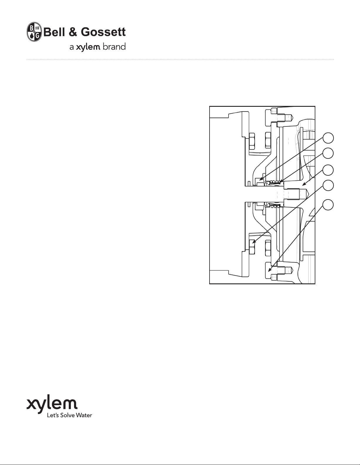
1
2
3
4
5
1. Seal Seat
2. Seal Head
3. Impeller
4. Motor Capscrew
5. Volute Capscrew
Xylem Inc.
8200 N. Austin Avenue
Morton Grove, Illinois 60053
Phone: (847) 966-3700
Fax: (847) 965-8379
www.bellgossett.com
Bell & Gossett is a trademark of Xylem Inc. or one of its subsidiaries.
© 2013 Xylem Inc. P2001387B October 2013
 Loading...