

Page 1
Little Red Booster Pumps
Installation, Operation, & Service Instructions
INSTRUCTION MANUAL
P15776
REVISION H
INSTALLER:
PLEASE LEAVE THIS MANUAL FOR THE OWNER’S USE.
Bell & Gossett
Bell & Gossett
NOTE:
Bell & Gossett recommends Bronze Booster Pumps be used
for pumping potable water.
DESCRIPTION
The Little Red Booster Pump features oil lubricated bearings,
carbon/ceramic seal, non-overloading permanent split-capacitor
motor with thermal protection and quiet-operating construction.
PUMP APPLICATION
The Little Red Booster Pump may be used for water circulating applications in hydronic and solar systems. It may also be
used for domestic water, but should be equipped with a
bronze pump body.
®
U
L
®
®
Page 2
2
SAFETY
INSTRUCTION
This safety alert symbol will be used in this manual and on the
pump safety instruction decal to draw attention to safety related
instructions. When used, the safety alert symbol means ATTENTION! BECOME ALERT! YOUR SAFETY IS INVOLVED!
FAILURE TO FOLLOW THE INSTRUCTION MAY RESULT IN
A SAFETY HAZARD.
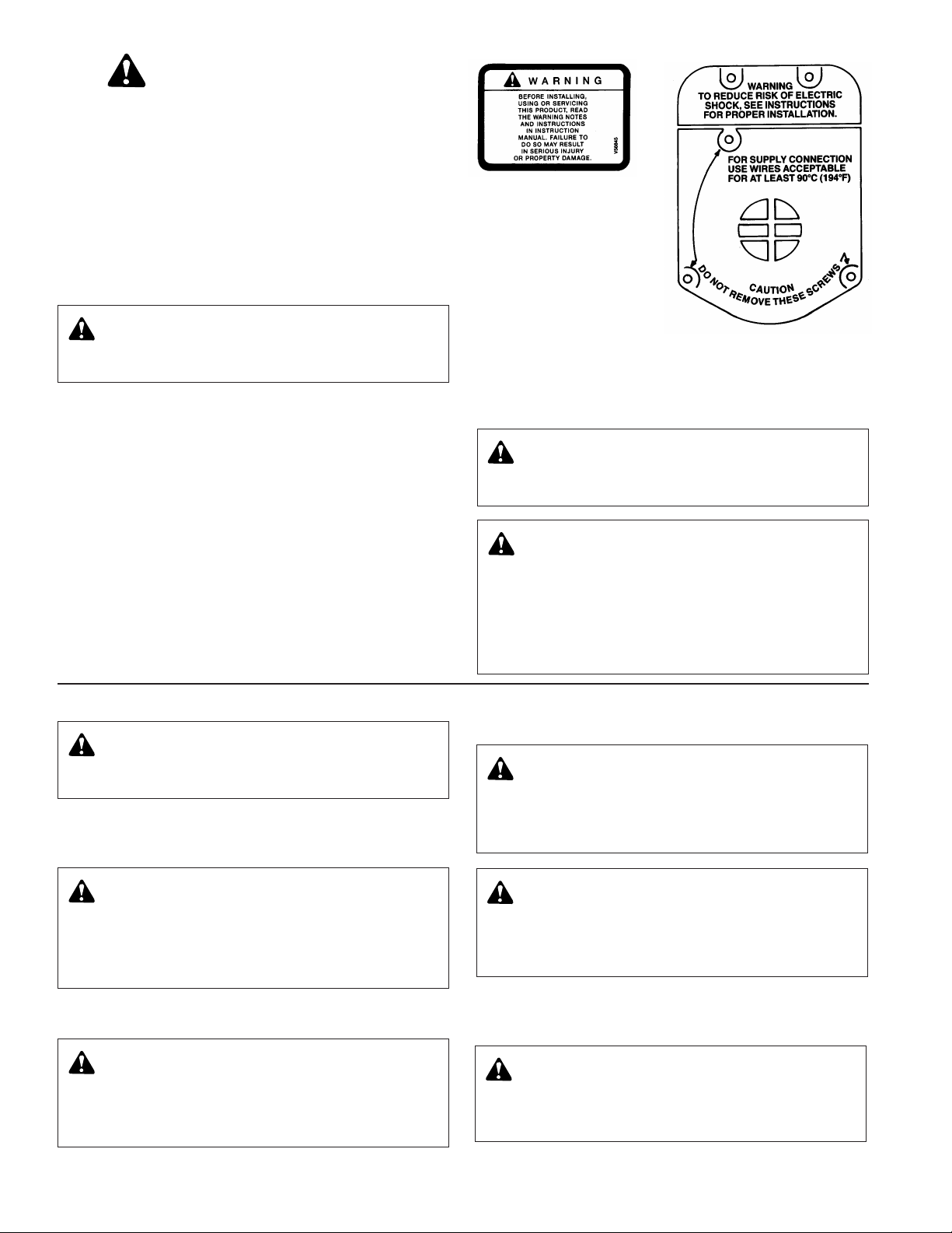
Your Little Red Booster Pump should have the warning label
displayed to the right (Fig. 2) affixed to the motor housing and
the warnings and cautions displayed at right (Fig. 3) clearly
marked in raised letters on the motor end covers. If any of
these warnings and cautions are missing or illegible, contact
your local Bell & Gossett Representative for a replacement.
ADDITIONAL SAFETY REQUIREMENTS
1. Electrical connections to be made by qualified electrician in
accordance with all national, state and local codes.
2. Adequate electrical grounding is required for the safe operation of the Little Red Booster Pump, and the use of grounded
metal conduit assures this requirement. If the means of connection to the supply-connection box (wiring compartment)
is other than grounded metal conduit, ground the pump
back to the service by connecting a copper conductor, at
least the size of the circuit conductors supplying the pump,
to the green grounding screw provided within the wiring
compartment.
Replace conduit box cover and secure with screws.
3. The maximum working pressure of the pump is listed on
the pump nameplate, do not exceed this pressure.
4. This pump is for indoor use only.
The motor housing cover is a functional component designed
to prevent accidental contact with the motor fan. Do not remove this cover unless power to the pump is disconnected
and locked out.
1. Close the valves on the suction and discharge sides of the
pump. (If no valves have been installed, it may be necessary to drain the system.)
2. Remove the conduit box cover by removing the two screws
at the top of the cover.
3. Disconnect the electrical supply lines to the pump.
4. Remove the four flange nuts and bolts and remove the
pump from the piping.
WARNING: Before installing, using or servicing this
product. Read the warning notes and instructions in
instruction manual. Failure to do so may result in injury or
property damage.
WARNING: Rotating Component Hazard
Do not operate pump without all guards in place.
Failure to follow these instructions could result in serious
personal injury or death, and property damage.
WARNING: Excessive Pressure Hazard
WARNING: Volumetric Expansion
The heating of water and other fluids causes volumetric
expansion. The associated forces may cause failure of the
system components and release of high temperature fluids.
This will be prevented by installing properly sized and located compression tanks and pressure relief valves. Failure
to follow these instructions could result in serious personal
injury or death, and property damage.
FIG. 2
FIG. 3
REMOVAL OF PUMP FROM EXISTING SYSTEM FOR REPLACEMENT
WARNING: Electrical Shock Hazard
Disconnect and lockout the power before servicing.
Failure to follow these instructions could result in serious
personal injury or death.
WARNING: Hot Water Hazard
Before draining the system, allow water to cool at
least 100°F (38°C), open the drain valve (take precautions
against water damage) and leave the drain valve open until
servicing is complete. Failure to follow these instructions
could result in serious personal injury, death and/or
property damage.
WARNING: Hot Water Hazard
Whenever disassembling a gasket joint, always use
a new gasket upon reassembly. NEVER RE-USE OLD
GASKETS. Failure to follow these instructions could result
in serious personal injury, death and/or property damage.
WARNING: Unexpected Start-Up Hazard
Single phase motors are equipped with automatic
reset overload protectors. The pump can restart without
warning. Disconnect and lockout power before servicing.
Failure to follow these instructions could result in serious
personal injury, death and/or property damage.
CAUTION: Temperature Hazard
Check surfaces for high temperatures, allow the
pump temperature to reach approximately 100°F (38°C),
before proceeding. Failure to follow these instructions
could result in moderate personal injury and/or property
damage.
WARNING: High Pressure Hazard
Pressure may be present in the pump body. This
pressure can be relieved by loosening the flange bolts and
shifting the pump assembly slightly to allow the pressurized water to escape. Failure to follow these instructions
could result in serious personal injury or death.
Page 3

3
PUMP INSTALLATION
Locate the pump so there is sufficient room for inspection, maintenance and service. Bell & Gossett recommends the installation of service valves on the suction and discharge of all circulators to facilitate servicing or replacement of the circulator
without draining the system.
Install suction and discharge flanges on the pipe ends. The
use of Teflon
®
* tape sealer or a high quality thread sealant is
recommended.
Be sure to minimize any pipe-strain on the pump. Support the
suction and discharge piping by the use of pipe hangers near
the pump. Line up the vertical and horizontal piping so that the
bolt-holes in the pipe flanges match the bolt-holes in the pipe
flanges.
[DO NOT ATTEMPT TO SPRING THE SUCTION OR
DISCHARGE LINES IN POSITION. THIS MAY RESULT IN
UNWANTED STRESS IN THE PUMP BODY, FLANGE CONNECTIONS AND PIPING.]
The code for Pressure Piping
(ANSI B31.1) lists many types of support available for various
applications.
Bell & Gossett flange gaskets must be installed between the
Little Red pump body flanges and the suction and discharge
pipe flanges. Suitable fasteners for this connection are also
supplied in the Bell & Gossett fastener pack.
Apply torque in even increments to both flange bolts until a
value of 175 in-lbs (2.01 Kg-m) is reached. Both the suction
and discharge flanges must be torqued in this manner.
MODE OF DISCHARGE
The Little Red Booster Pump can be installed to discharge up
or down, horizontally left or right, but the oiling port must
always be in the twelve o’clock position (on top). Arrow on
body must point in direction of flow.
TYPICAL INSTALLATION SCHEMATIC
POWER SOURCE 115 Volt. 60 Hz.1ø
ELECTRICAL WIRING
A. Loosen screws securing the conduit box (wiring compart-
ment) cover, removing screws and cover.
B. Select one of the two holes in the side of the conduit box
and wire the motor to a 115 volt, 60 hertz, single phase
power source with number 14 AWG copper electrical wire.
Refer to your local code for wiring restrictions. Plug the
unused hole in the side of the conduit box with the plug
provided.
C. Connect the ground wire to the inside of the conduit box
with the green screw provided.
NOTE: Supply and grounding wires must be suitable for at
least 90°C (194°F).
ELECTRICAL CHARACTERISTICS
Model LR-20BF is rated at 1/20 HP, 115 volts, 1.1 F.L. amps,
60 HZ, 1ø (single phase), 2900 RPM.
Model LR-15B is rated at 1/12 HP, 115 volts, 1.75 F.L. amps,
60 HZ, 1ø (single phase), 3150 RPM.
Little Red Booster Pumps are protected with an inherent overheating device and do not require external overload protection.
SYSTEM PREPARATION
Prior to pump start up, closed heating and cooling systems
should be cleaned, drained, and refilled with clean water.
System ph must be maintained between 7 and 9.
Pressurize the pump body slowly while checking for leaks at
all gasketed joints.
PRIMING
Do not run the pump dry. These pumps must be filled with
liquid before being placed in service. Air should be vented
from the system by means of an air vent located at a high
point in the system.
LUBRICATION
All new Bell & Gossett Little Red Booster Pumps are thoroughly
tested at the factory and have been enhanced with a superior
lubrication system which requires a minimum of attention. Please
refer to the recommended lubrication instructions noted below
for the type of pump service required.
1. At installation: Pumps have been factory lubricated and do
not require additional lubrication at start-up.
2. Heating system operation: Pumps should be lubricated at
the start of every heating season. Add one tube (5cc) of
Bell & Gossett P15775 lubricating oil.
3. Continuous duty: Pump should be lubricated every six (6)
months. Add one tube (5cc) of Bell & Gossett P15775 lubricating oil.
NOTE: In lieu of genuine Bell & Gossett P15775 lubricating
oil, use one teaspoon of Mobile 1, SAE 5W-30, motor oil as
required.
IMPORTANT: Over oiling of the pump will result in the
overflow of oil from the oil reservoir.
WARNING: Electrical Shock Hazard
Disconnect and lockout the power before servicing.
Failure to follow these instructions could result in serious
personal injury or death.
WARNING: Electrical Shock Hazard
Be certain that all connections are secure and the
conduit box cover is closed before electrical power is connected. Failure to follow these instructions could result in
serious personal injury or death.
FIG. 4
RIGHT OR
LEFT
UP OR
DOWN
FIG. 5
PUMP
MOTOR
FUSIBLE DISCONNECT
OR CIRCUIT BREAKER
BY OTHERS
PUMP MOTOR
INHERENTLY
PROTECTED
TO REMOTE
CONTROL
IF REQUIRED
WARNING: Hot Water Leakage Hazard
Pressurize the pump body slowly while checking for
leaks at all joints with gaskets. Failure to follow these
instructions could result in serious personal injury and/or
property damage.
*Teflon®is a registered trademark of E.I. DuPont de Nemours and Company.
Page 4

Bell & Gossett
© COPYRIGHT 1982, 2004 BY ITT INDUSTRIES, INC.
PRINTED IN U.S.A. 1-04
USA
Bell & Gossett
8200 N. Austin Avenue
Morton Grove, IL 60053
Phone: (847) 966-3700
Facsimile: (847) 966-9052
http://www.bellgossett.com
INTL.
Bell & Gossett / Export Dept.
8200 N. Austin Avenue
Morton Grove, IL 60053
Phone: (847) 966-3700
Facsimile: (847) 966-8366
http://www.bellgossett.com
CANADA
Fluid Products Canada
55 Royal Road
Guelph, Ontario,
N1H 1T1, Canada
Phone: (519) 821-1900
INSTRUCTIONS FOR PUMP REPAIR
1. Follow steps 1 through 4 of section titled “REMOVAL OF
PUMP FROM EXISTING SYSTEM FOR REPLACEMENT.”
2. Loosen the four capscrews that hold the motor housing to
the pump body. Remove these screws and remove the
housing from the pump body.
3. Place the pump on a flat work surface and insert the plastic
assembly tool (furnished with the repair kit) into the rear
motor housing coverplate middle horizontal vent holes.
Push forward until it engages the rotor cooling fins. This will
lock the rotor allowing removal of the impeller.
4. Remove the impeller nut – left hand thread! – from the pump
shaft. Remove the impeller and rotating seal assembly.
5. Clean the ceramic seat with a clean rag and inspect for
grooving or cracks. If it shows no grooving or cracks, it
may be cleaned and reused.
6. If the ceramic is to be replaced, the face plate must be removed from the motor housing. Remove it by gently prying it away from the motor housing.
7. Remove the damaged ceramic seat and boot if necessary.
Reinstall new parts in the face plate recess and reposition
the face plate on the motor housing. Gently tap the face
plate evenly around its diameter driving it into the recess
provided in the motor housing.
INSTRUCTIONS FOR PUMP REPAIR
8. Press the rotor fully forward with the plastic assembly
tool. Clean the shaft and sleeve before installing the seal.
9. Press the replacement carbon seal assembly firmly into
the recess in the back side of the impeller.
10. Assemble the seal/impeller assembly to the pump shaft
by pushing the rotor fully forward with the plastic assembly tool. Then slide the seal/impeller assembly onto the
pump shaft until the seal face contacts the ceramic seat.
11. Continue holding the rotor fully forward with the assembly
tool. Install and torque the impeller nut – left hand thread!
– to 15 in-lb (0.17 Kg-m) torque.
12. Clean the recess in the pump body and install a new body
gasket.
13. Install the pump in the body and secure with four capscrews. Apply torque evenly in a criss cross pattern to 40
in-lb (0.46 Kg-m) increments to a torque of 80 in-lb (0.92
Kg-m).
14. Reinstall into the system using new flange gaskets. For
instructions, see sections “PUMP INSTALLATIONS”
through and including “LUBRICATION.”
CONDUIT BOX
COVER
CAPACITOR
NAME PLATE
CAPACITOR RETAINER
STATOR & HSG. ASM.
OIL
HOLE
PLUG
BODY
BODY GASKET
COVERPLATE ASM
WICK COVERPLATE
IMP. CUSHION
IMP. NUT
SHAFT SLEEVE
SEAL ASM
IMPELLER
PERMAWICK
THRUST
COLLAR
OIL RETAINER
THRUST DRIVER
MOTOR HSG. COVER
FIG. 6
ROTOR & SHAFT ASM.
PERIODIC INSPECTION
Bell & Gossett Booster Pumps are designed to provide years of
trouble free service. It is recommended that periodic inspections be made to check for potential problems with the pump. If
PERIODIC INSPECTION
any leakage or evidence of leakage is present repair or replace
the unit.
 Loading...