

Page 1
INSTRUCTION MANUAL
MM-217L
Page 2
2
Approximate
Distance Above
Cast Line Differential
Setting In. (mm) In. (mm)
Pump Off
15
/16(24)
5
/16(8)
Pump On
5
/8(16)
Burner On
5
/8(16)
3
/8(16)
Burner Off
1
/4(6.4)
Pump Off 13/8(41)
3
/4(19)
Pump On
5
/8(16)
Burner On
7
/8(22)
7
/8(22)
Burner Off 0 (0)
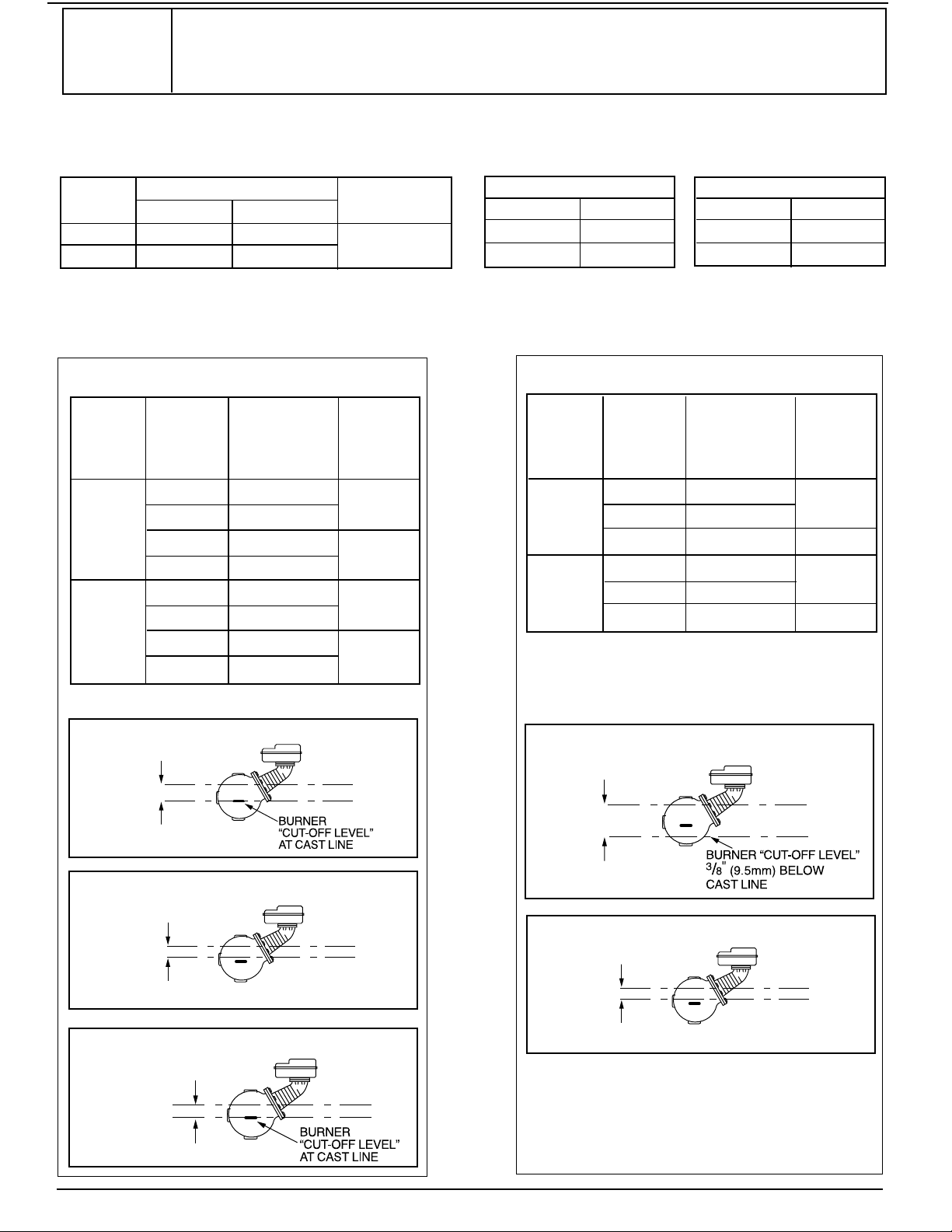
OPERATION
Maximum Pressure: 150 psi (10.5 kg/cm2)
Settings and Differential Pressures
Values are ± 8” (3.2mm).
Series 150S, 157S
150 psi (10.5 kg/cm
2
) Levels
150 psi (10.5 kg/cm
2
) Levels
0 psi
(0 kg/
cm2)
150 psi
(10.5 kg/
cm2)
Approximate
Distance Above
Cast Line Differential
Setting In. (mm) In. (mm)
Pump Off
15
/16(24)
3
/8(16)
Pump On
9
/16(14)
Burner Off 0 (0) N/A
Pump Off 17/16(37)
3
/4(19)
Pump On
11/16
(17)
Burner Off - 3/8(-16)
N/A
Model 150S-MD, and 157S-MD
0 psi
(0 kg/
cm2)
150 psi
(10.5 kg/
cm
2
)
Pressure
Pressure
BURNER OFF
BURNER ON
7
/8"
DIFFERENTIAL
(22mm)
PUMP
OFF
BURNER
OFF
NORMAL BOILER
WATER LINE
1
3
/8"
DIFFERENTIAL
(35mm)
PUMP OFF
PUMP ON
3
/4"
DIFFERENTIAL
(19mm)
PUMP OFF
PUMP ON
3
/4"
DIFFERENTIAL
(19mm)
PUMP
OFF
BURNER
OFF
NORMAL BOILER
WATER LINE
1
13
/16"
DIFFERENTIAL
(46mm)
Enclosure rating: NEMA 1 General Purpose
PumpCircuit Rating (Amperes)
Voltage Full Load Locked Rotor Pilot Duty
120 VAC 7.4 44.4
345 VA at
240 VAC 3.7 22.2
120 or 240 VAC
Electrical Ratings
Alarm Circuit Rating
Voltage Amps
120 VAC 1
240 VAC 1/2
Motor Horsepower
Voltage Hp
120 VAC
1/3
240 VAC 1/3
CAUTION:
A more frequent replacement interval may be necessary based on the condition of
•
the unit at time of inspection. McDonnell Miller s warranty is one (1) year from date
of installation or two (2) years from the date of manufacture.
&
'
Page 3
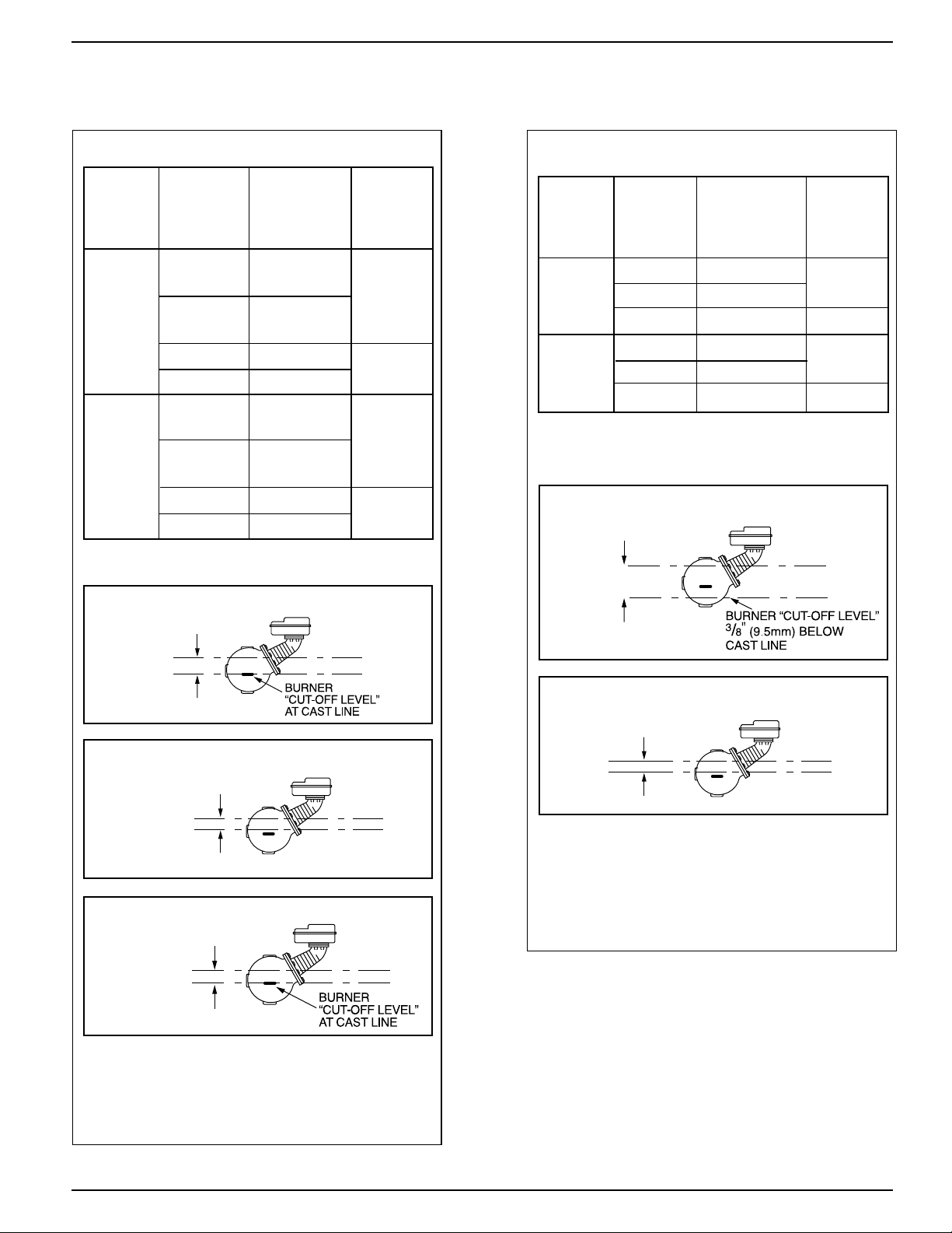
3
Approximate
Distance Above
Cast Line Differential
Setting In. (mm) In. (mm)
Motorized
15
/16(24)
Valve Closed
5
/16(8)
Motorized
5
/8(16)
Valve Open
Burner On
5
/8(16)
3
/8(16)
Burner Off
1
/4(6.4)
Motorized 13/8(41)
3
/4(19)
Valve Closed
Motorized
5
/8(16)
Valve Open
Burner On
7
/8(22)
7
/8(22)
Burner Off 0 (0)
Values are ± 8” (3.2mm).
NOTE: Due to the slower operation of some
motorized valves, complete valve opening
or closing will occur at slightly different
levels than indicated above.
Model 158S
150 psi (10.5 kg/cm
2
) Levels
0 psi
(0 kg/
cm2)
150 psi
(10.5 kg/
cm
2
)
Pressure
Settings and Differential Pressures (continued)
150 psi
(10.5 kg/
cm2)
Approximate
Distance Above
Cast Line Differential
Setting In. (mm) In. (mm)
Pump Off
15
/16(24)
3
/8(16)
Pump On
9
/16(14)
Burner Off 0 (0) N/A
Pump Off 17/16(37)
3
/4(19)
Pump On
11/16
(17)
Burner Off -
3/8
(-16)
N/A
Model 158S-MD
0 psi
(0 kg/
cm2)
Pressure
150 psi (10.5 kg/cm2) Levels
NOTE: Due to the slower operation of some
motorized valves, complete valve opening
or closing will occur at slightly different
levels than indicated above.
BURNER OFF
BURNER ON
7
/8"
DIFFERENTIAL
(22mm)
MOTORIZED
VALV E
CLOSED
BURNER
OFF
NORMAL BOILER
WATER LINE
1
3
/8"
DIFFERENTIAL
(35mm)
MOTORIZED
VALV E
CLOSED
MOTORIZED
VALV E
OPEN
3
/4"
DIFFERENTIAL
(19mm)
MOTORIZED
VALVE
OPEN
CLOSED
3
/4"
DIFFERENTIAL
(19mm)
MOTORIZED
VALV E
CLOSED
BURNER
OFF
NORMAL BOILER
WATER LINE
1
13
/16"
DIFFERENTIAL
(46mm)
Page 4
4
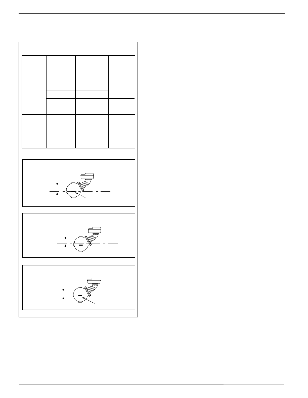
Values are ± 8” (3.2mm).
150 psi (10.5 kg/cm2) Levels
Approximate
Distance Above
Cast Line Differential
Setting In. (mm) In. (mm)
Pump #1 Off15/16(24)
5
/16(8)
Pump #1 On5/8(16)
Pump #2 Off5/8(16)
3
/8(16)
Pump #2 On1/4(6.4)
Pump #1 Off 13/8(41)
3
/4(19)
Pump #1 On5/8(16)
Pump #2 Off7/8(22)
7
/8(22)
Pump #2 On
0 (0)
Model 159S
0 psi
(0 kg/
cm2)
150 psi
(10.5 kg/
cm
2
)
Pressure
Settings and Differential Pressures (continued)
PUMP #1
OFF
PUMP #1
ON
NORMAL BOILER
WATER LINE
(19mm)
3
/4"
DIFFERENTIAL
PUMP #2 ON
AT CAST LINE
7
/8"
DIFFERENTIAL
(22mm)
PUMP #2
ON
PUMP #2
OFF
PUMP #1
OFF
PUMP #2
ON
PUMP #2 ON
AT CAST LINE
NORMAL BOILER
WATER LINE
1
3
/8"
DIFFERENTIAL
(35mm)
Page 5

a. Using a pipe wrench, unscrew the plastic
float blocking plug (A) from the low water
cut-off body (B).
5
If the control will be the primary low
water fuel cut-off, size the steam (top)
and water (bottom) equalizing pipe lengths
so that the horizontal cast line on the body
is 1a” (35mm) below the boiler’s normal
water level, but not lower than the lowest,
safe permissible water level, as determined by the boiler manufacturer.
OR
If the control will be the secondary low
water fuel cut-off, size the steam (top) and
water (bottom) equalizing pipe lengths so
that the horizontal cast line on the body is
at or above, the lowest, safe permissible
water level, as determined by the boiler
manufacturer.
STEP 2 - Installing the Low Water Cut-Off
STEP 1 - Determine the Elevation at Which the
Low Water Cut-Off/Pump Controller Must be Installed
INSTALLATION
TOOLS NEEDED:
Two (2) pipe wrenches, one (1) flathead screw
driver, and pipe sealing compound.
IMPORTANT: Follow the boiler manufacturer's
instructions along with all applicable codes and
ordinances for piping, blow down valve and water
gauge glass requirements.
13/8"
STEAM EQUALIZING PIPE
VERTICAL EQUALIZING PIPE
BLOW DOWN VALVE
NORMAL BOILER WATER LINE
AS A PRIMARY
LOW WATER CUT-OFF/PUMP CONTROLLER
BURNER “CUT-OFF LEVEL” AT CAST LINE
LOWEST PERMISSIBLE
WATER LEVEL
(35mm)
WATER
EQUALIZING
PIPE
STEAM EQUALIZING PIPE
VERTICAL EQUALIZING PIPE
BLOW DOWN VALVE
AS A SECONDARY
LOW WATER CUT-OFF/PUMP CONTROLLER
BURNER “CUT-OFF LEVEL” AT CAST LINE
LOWEST PERMISSIBLE
WATER LEVEL
BURNER OFF
WATER
EQUALIZING
PIPE
Series 150S
(except Model 150S-B)
Models 150S-B Series 157S
B
A
A
B
B
A
Page 6

b. Install a water gauge glass (J).
Note: Gauge glass and tri-cocks
not included with product.
J
J
H
a. Install a water column (H) (not
included with product) for all models
except Series 157S (with integral
water column).
Series 157S
All Other Models
6
C
A
A
C
F
G
E
D
c. Mount and pipe the low water cut-off (D) on
a vertical equalizing pipe (E) at the required
elevation level, as determined in Step 1.
Install a full ported blow down valve (G)
directly below the lower cross of the water
equalizing pipe (F).
Note: 1” NPT tappings are provided, with
the exception of some 157 and 157S models
which are 14” NPT.
b. For Model 150S-B and Series 157S
(For all other models, proceed to Step 3).
Screw the w” NPT steel plug (C) (provided)
in tapping (A).
Series 157S
Models 150S-B
STEP 3 - Installing a Water Gauge Glass
(Required on all steam boilers)
The plug must be reinstalled before control is
shipped installed on the boiler, and removed
when boiler is installed after shipment.
Failure to follow this caution may damage float
and operating mechanism.
!
CAUTION
Page 7

STEP 4 - Electrical Wiring
• To prevent a fire, do not use this product to switch currents over 7.4A, 1/3 Hp at 120 VAC or 3.7A, 1/3 Hp at 240
VAC, unless a starter or relay is used in conjunction with it.
• To prevent electrical shock, turn off the electrical power before making electrical connections.
• This low water cut-off must be installed in series with all other limit and operating controls installed on the
boiler. After installation, check for proper operation of all of the limit and operating controls, before leaving
the site.
• Modification of the switch assembly before or after installation could cause damage to the boiler and/or
boiler system.
Failure to follow this warning could cause electrical shock, an explosion and/or a fire, which could result in
property damage, personal injury or death.
!
WARNING
Switch Operation
For all Models except 158S and 159S
For Model 158S
Boiler feed pump off,
burner on, alarm off.
Boiler feed pump on,
burner on, alarm off.
Boiler feed pump on,
burner off, alarm on.
1 2 4 5 6 1 2 4 5 6
1 2 4 5 6
Motorized valve closed,
burner on, alarm off.
Motorized valve open,
burner on, alarm off.
Motorized valve open,
burner off, alarm on.
4 5 6
1 2
3
4 5
1 2
3
4 5
1 2
3
6 6
For Model 159S
Pump #1 off,
pump #2 off.
Pump #1 on,
pump #2 off.
Pump #1 on,
pump #2 on.
1 2 5 6 1 2 5 6
1 2 5 6
K
a. Using a flathead screwdriver, remove the
junction box cover (K).
7
Page 8

Page 9

9
WIRING DIAGRAMS
For Motorized Valves, refer to the valve manufacturer's wiring instructions.
Low Water Cut-Off Only
1. Main Line Switch - For burner circuits within the
switch’s electrical rating.
1. Main Line Switch - For burner circuits within
the switch’s electrical rating.
2. Pilot Switch - To holding coil of a starter when
the burner circuit exceeds the switch’s electrical
rating.
LINE LOAD
12 456
12 456
ALARM
NEUTRAL
HOT
ALARM
NEUTRAL
HOT
12 456
12 456
SEE PUMP
CONTROL
CIRCUIT
TO NEUTRAL
TO BURNER CONTROL CIRCUIT
HOT
ALARM
12 456
LOAD
LINE (3 PHASE)
SEE PUMP
CONTROL
CIRCUIT
ALARM
OR
OR
OR
Combination Pump Control, Low Water Cut-Off and Alarm
Alarm Circuit Only
1. Low Water Alarm 2. High Water Alarm
2. Pilot Switch - To holding coil of a starter when
the burner circuit exceeds the switch’s electrical
rating.
Pump Control Only
1. Install a starter or relay in pump control circuit,
as shown, to prevent damage to snap switch
and help insure proper switch/control operation.
Failure to do so may shorten the life of the
switch when actual amperage exceeds
switch rating.
2. Connect wires from holding coil of pump starter
or relay to terminals 1 and 2 as shown.
NOTE: To help insure most effective operation,
balance boiler feed pump(s) to deliver required water
feeder rate to match boiler steaming requirements.
NOTE: For Model 159S, use terminals 5 and 6 from
starter or relay for pump # 2.
LINE
12 456
LOAD
LINE
12 456
LOAD
Page 10

10
STEP 5 - Testing
OFF
ON
a. Turn on the electric power to the boiler. With the
boiler empty the pump should go on and the burner
must remain off.
IMPORTANT: Follow the boiler manufacturer’s start-up and operating instructions along with all applicable
codes and ordinances. Note: Water levels stated below are only for 150 psi (10.5 kg/cm
2
) operation.
This control is factory calibrated for specific applications. The following testing procedure is only meant to
serve as a verification of proper operating sequence.
Dimensions provided are typical for a boiler not being fired and/or not at pressure. Actual operating
ranges are shown on page 2 in the "Operation" section.
If the burner comes on, immediately turn the boiler off and make the
necessary corrections.
Failure to follow this warning could cause an explosion or fire and
result in property damage, personal injury or death.
!
WARNING
M
J
(22mm)
b. The boiler should begin to fill with water.
Watch the gauge glass (J) until the water
level reaches approximately d” (22mm)
above the horizontal cast line (M) on the low
water cut-off.
IMPORTANT: If water does not start filling the
boiler, immediately turn off the the boiler and
make the necessary corrections.
6. Re-attach the junction box cover (K).
K
Note:
Cover must be installed correctly as shown
7
/8"
Page 11

11
e.
To prevent serious personal injury from steam pipe blow down, connect a pipe to avoid exposure to
steam discharge.
Failure to follow this caution could cause personal injury.
!
CAUTION
INSTALLATION COMPLETE
M
J
(22mm)
c. For automatic reset models only. When the water
level reaches approximately d” (22mm) above the
horizontal cast line (lower for MD models) the burner
should come on (pump #2 should shut off with
Model 159S).
OR
For manual reset models only. When the water
level reaches approximately d” (22mm) above the
horizontal cast line press the reset button (N). The
burner should then come on.
d. Continue watching the gauge glass (J) to
see that the water continues to rise to
approximately 1a” (35mm) (1
7
/16” (37mm)
for MD models) above the horizontal cast
line (M). The pump should shut off (the
motorized valve should close with Models
158 and 158S, or with Models 159 and
159S, pump #1 should shut off).
N
Snap Switch Models
Blow down the control when the water in the boiler
is at its normal level and the burner is on. Follow
Blow Down Procedure found in Maintenance
Section on the last page of these instructions.
7
/8"
Page 12

Xylem Inc.
8200 N. Austin Avenue
Morton Grove, Illinois 60053
Phone: (847) 966-3700
Fax: (847) 965-8379
www.mcdonnellmiller.com
McDonnell & Miller is a trademark of Xylem Inc. or one of its subsidiaries.
© 2014 Xylem Inc. MM-217L September 2014 Part No. 210341
 Loading...