

Page 1
BELL & GOSSETT
SERVICE MANUAL
HT-320B-SM
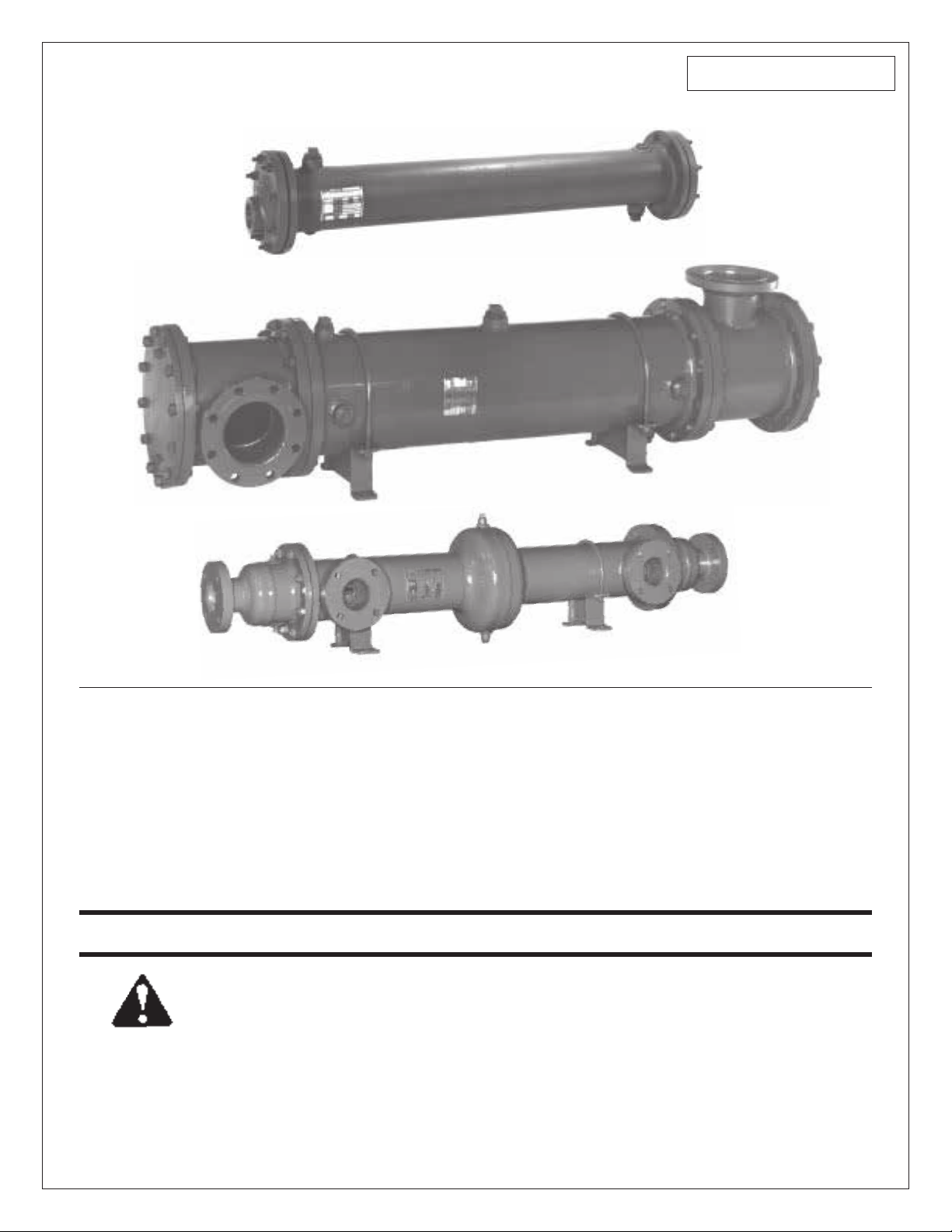
TYPE “OF” WITH CAST IRON BONNET HEADS
TYPE “OF” WITH STEEL CHANNEL HEADS
TYPE “OE” WITH STEEL BONNET HEADS
Installation, Operation and
Maintenance Manual for
Models “OF” & “OE” Straight Tube,
Fixed Tubesheet Heat Exchangers
INSTALLER: PLEASE LEAVE THIS MANUAL FOR THE OWNER’S USE.
SAFETY
INSTRUCTION
This safety alert symbol will be used in this manual to draw
attention to safety related instructions. When used, the safety
alert symbol means ATTENTION! BECOME ALERT! YOUR
SAFETY IS INVOLVED! FAILURE TO FOLLOW THESE INSTRUCTIONS MAY RESULT IN A SAFETY HAZARD.
© COPYRIGHT 1984, 1995
Bell & Gossett
Morton Grove, IL, U.S.A.
Page 2
INSTALLATION
1. Provide sufficient clearance at each end of the heat exchanger
to permit rodding the tubes.
2. Provide valves and by-passes in the piping systems so that
both the shell and tube sides may be by-passed to permit
inspection or repair.
3. Provide thermometer well and pressure gauge connections in
all piping to and from the unit and locate as near the unit as
possible.
4. Provide convenient means for frequently cleaning the unit as
suggested under “Maintenance.”
5. Provide necessary air vent cocks for units so they can be
purged to prevent or relieve vapor or gas binding of either the
tube or the shell sides.
6. Foundations must be adequate so that exchangers will not
settle and cause piping strains. Foundation bolts should be
set to allow for setting inaccuracies. In concrete footings, pipe
sleeves at least one size larger than bolt diameter slipped over
the bolt and cast in place are best for this purpose, as they
allow the bolt center to be adjusted after the foundation has
set.
7. Loosen foundation bolts at one end of unit to allow free
expansion of shells. Oval holes in foundation brackets are
provided for this purpose.
8. Set exchangers level and square so that pipe connections
may be made without forcing.
9. Inspect all openings in exchanger for foreign material. Remove all thread protectors and shipping pads just before
installing. Do not expose units to the elements with pads or
other covers removed from openings since rain water may
enter the unit and cause severe damage due to freezing.
2
10. Be sure the entire system is clean before starting operation to
prevent plugging of tubes with sand or refuse. The use of
strainers in settling tanks in pipe lines leading to the unit is
recommended.
11. Drain connections should not be piped to a common closed
manifold.
12. Steam hammer can cause serious damage to the tubes of any
heat exchanger. A careful consideration of the following points
before an installation is made can prevent costly repairs which
may be caused by steam hammer.
a. A vacuum breaker and/or vent, should be used in accor-
dance with the type of steam system installed.
b. The proper trap for the steam system installed should be
used.
c. The trap and the condensate return line to the trap should
be properly sized for the total capacity of the convertor.
d. The trap should be sized for the pressure at the trap, not
the inlet pressure to the steam controller.
e. The trap must drain into an unpressurized condensate
return system. Condensate return lines must not be run at
an elevation above the bottom of the heat exchanger. To do
so may result in a buildup of the condensate level in the
heat exchanger, which could cause water hammer and
damaged tubes.
CAUTION: During times of shutdown, volumetric
expansion can occur. We recommend the installation
of a properly sized relief valve on both sides of the heat
exchanger.
Page 3

OPERATION
1. When placing a unit in operation, open the vent connections
and start to circulate the cold medium only. Be sure that the
passages in the exchanger are entirely filled with the cold fluid
before closing the vents. The hot medium should then be
introduced gradually until all passages are filled with liquid,
close vents and slowly bring the unit up to temperature.
2. Start operation gradually. Do not admit hot fluid to the unit
suddenly when empty or cold. Do not shock unit with cold fluid
when unit is hot.
CAUTION:
unit. Failure to do so can cause damage to the heat
exchanger.
3. In shutting down, flow of hot medium should be shut off first.
If it is necessary to stop circulation of cooling medium the circulation of hot medium should also be stopped by by-passing
or otherwise.
4. Do not operate equipment under conditions in excess of those
specified on nameplate.
WARNING:
within the design pressure and temperature on the
nameplate may result in damage to the heat exchanger and
potential injury to adjacent personnel.
5. Drain all fluids when shutting down to eliminate possibility of
freezing and corrosion. To guard against water hammer, condensate should be drained from steam heaters and similar
apparatus both when starting up and when shutting down.
6. In all installations there should be no pulsation of fluids since
this causes vibration and strain with resulting leaks.
7. All gasketed joints should be checked after starting for leaks
and tightened if necessary.
Fluids must be gradually introduced to the
Failure to operate the heat exchanger
d. If none of the above described methods are effective for
the removal of hard scale or coke a mechanical means
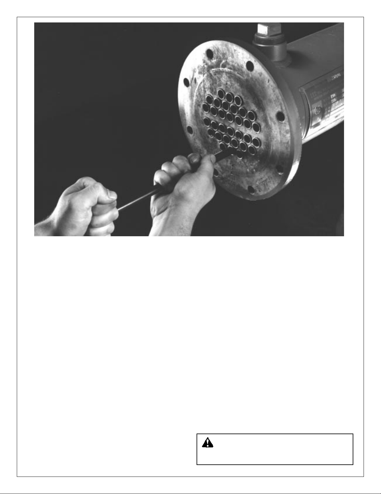
may be used. The interior of the tubes may be rodded.
e. The exterior or shell side of the tubes of a fixed tube sheet
heat exchanger can only be cleaned chemically by using a
chemical dissolved in water solution. We suggest that the
user contact the manufacturer of the cleaning chemical for
instructions.
WARNING:
Care must be exercised when handling
certain fluids. Follow manufacturers instructions. Use
eye and skin protection. Wear a respirator when required.
4. To clean or inspect inside of tubes, remove channel cover and
rear head. On exchangers having bonnet type heads (without
channel cover), piping must be disconnected and both heads
removed.
5. Do not attempt to clean tubes by blowing steam through individual tubes. This overheats the tube and results in tube
expansion strains and sometimes leaking tubes.
6. When replacing heads, use a torque wrench.* Tighten
diameter bolts to 40 ft. lbs. and
5
/8" diameter bolts to 80 ft. lbs.
1
/2"
If the gasket joint still leaks, tighten in 5 ft. lbs. increments until
leak stops.
* The above torque values apply to well lubricated nut bearing
surfaces.
7. All bolted joints should be tightened uniformly and in a diametrically staggered pattern as illustrated below:
START
1
6
9
14
4
16
11
8
3
13
MAINTENANCE
1. Do not open heads until all pressure is off equipment and the
unit is drained.
2. Do not blow out heat exchangers with air when operating fluids
are of a flammable or otherwise hazardous nature.
WARNING:
clothing, equipment, etc.) to protect personnel from
injury due to escaping fluids.
3. Provide convenient means for frequently cleaning heat
exchangers as suggested below:
a. Circulating hot wash oil or light distillate through tubes or
shell at good velocity will effectually remove sludge or other
similar soft deposits.
b. Soft salt deposits may be washed out by circulating hot
fresh water.
c. Some cleaning compounds on the market, such as
“Oakite” may be used to advantage for removing sludge or
coke, provided hot wash oil or water, as described above,
does not give satisfactory results.
Proper precautions must be taken (special
7
12
2
15
10
5
8. Frequently and at regular intervals, observe interior and exterior condition of all tubes and keep them clean. Frequency of
cleaning should be according to scale build-up.
CAUTION:
Neglect in keeping all tubes clean may
result in complete stoppage of flow through some
tubes with consequent overheating of these tubes, resulting
in severe expansion strains, leaking tube joints, and damage
to the heat exchanger.
9. Exchangers subject to fouling or scaling should be cleaned
periodically. A light sludge or scale coating on the tube greatly
reduces its effectiveness. Therefore, low-fouling fluids should
be used in the shell side of all heat exchangers with nonremovable tube bundles. A marked increase in pressure drop
and/or reduction in performance usually indicates cleaning is
necessary, especially if the unit has been checked for air or
vapor binding and this has been found not to be the cause.
Since the difficulty of cleaning increases rapidly as the scale
thickens or deposits increase, the interval between cleanings
should not be excessive.
3
Page 4

CASING AND TUBE
BUNDLE ASSEMBLY
FRONT
HEAD
FRONT
HEAD
GASKET
NAMEPLATE
CROSS SECTIONAL VIEW OF
FIXED TUBE CONSTRUCTION
When ordering replacement parts give name of part,
National Board Number and factory number from nameplate.
REAR
HEAD
GASKET
REAR
HEAD
For further information, contact Bell & Gossett Heat Transfer Products, 175 Standard Parkway, Cheektowaga, NY 14227,
Phone (716) 862-4171 — Facsimile (716) 862-4176.
PRINTED IN U.S.A. 5-95
Bell & Gossett
Morton Grove, IL, U.S.A.
 Loading...