

Page 1
BELL & GOSSETT
SERVICE MANUAL
HT-205B-SM
Installation, Operation and
Maintenance Manual for
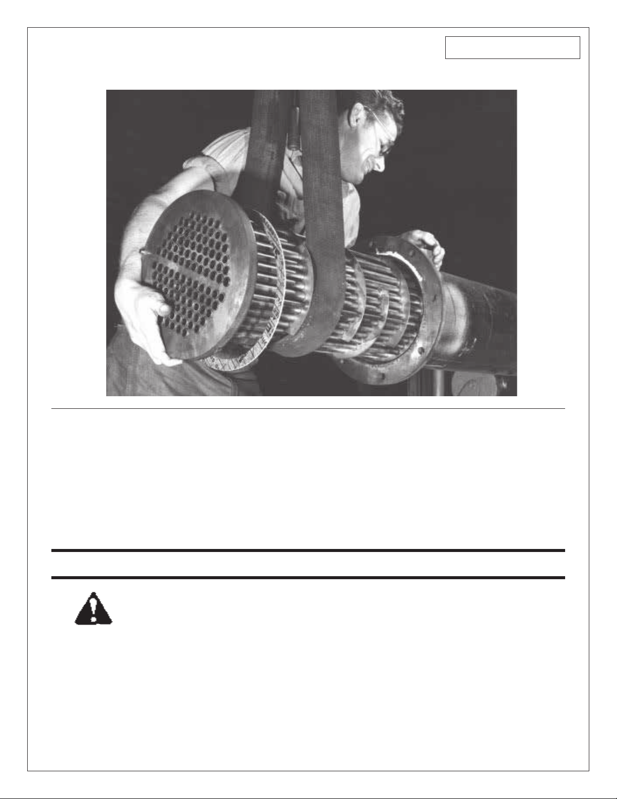
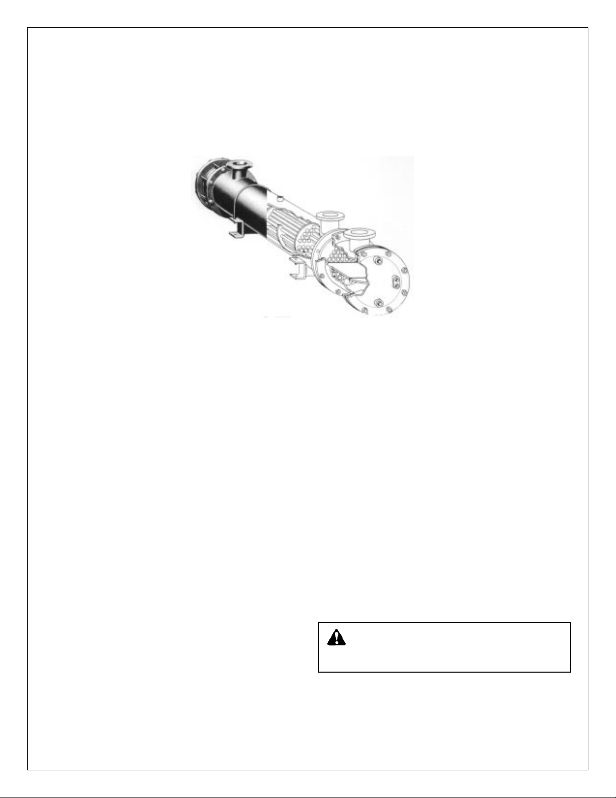
Models OC, GC & ACA Straight Tube,
Removable Bundle Heat Exchangers*
*Also includes procedures for MEA & MEAH tube bundles.
INSTALLER: PLEASE LEAVE THIS MANUAL FOR THE OWNER’S USE.
SAFETY
INSTRUCTION
This safety alert symbol will be used in this manual to draw
attention to safety related instructions. When used, the safety
alert symbol means ATTENTION! BECOME ALERT! YOUR
SAFETY IS INVOLVED! FAILURE TO FOLLOW THESE INSTRUCTIONS MAY RESULT IN A SAFETY HAZARD.
© COPYRIGHT 1984, 1995 BY
Bell & Gossett
Morton Grove, IL, U.S.A.
Page 2
INSTALLATION
1. Provide sufficient clearance at the stationary tube sheet end
of the unit to permit removal of tube bundles from shells. On
the packed floating tube sheet end, a space of 3 or 4 feet
should be provided to permit the removal of the rear head,
packing and retainer rings.
2. Provide valves and by-passes in the piping systems so that
both the shells and tube bundles may be by-passed to permit
cutting out the unit for inspection or repairs.
3. Provide thermometer wells and pressure gauge connections
in all piping to and from the unit and located as near the unit
as possible.
4. Provide convenient means for frequently cleaning the unit as
suggested under “Maintenance.”
5. Provide necessary air vent cocks for units so they can be
purged to prevent or relieve vapor or gas binding of either the
tube or the shell sides.
6. Foundations must be adequate so that exchangers will not
settle and cause piping strains. Foundation bolts should be
set to allow for setting inaccuracies. In concrete footings, pipe
sleeves at least one size larger than bolt diameter slipped over
the bolt and cast in place are best for this purpose, as they
allow the bolt center to be adjusted after the foundation has
set.
7. Loosen foundation bolts at one end of unit to allow free
expansion of shells. Oval holes in foundation brackets are
provided for this purpose.
8. Set exchangers level and square so that pipe connections
may be made without forcing.
9. Inspect all openings in exchanger for foreign material. Remove all wooden plugs and shipping pads just before
installing. Do not expose units to the elements with pads or
other covers removed from nozzles or other openings since
rain water may enter the unit and cause severe damage due
to freezing.
10. Be sure the entire system is clean before starting operation to
prevent plugging of tubes with sand or refuse. The use of
strainers in settling tanks in pipe lines leading to the unit is
recommended.
11. Drain connections should not be piped to a common closed
manifold.
12. Steam hammer can cause serious damage to the tubes of any
heat exchanger. A careful consideration of the following points
before an installation is made can prevent costly repairs which
may be caused by steam hammer.
a. A vacuum breaker and/or vent, should be used in accor-
dance with the type of steam system installed.
b. The proper trap for the steam system installed should be
used.
c. The trap and the condensate return line to the trap should
be properly sized for the total capacity of the convertor.
d. The trap should be sized for the pressure at the trap, not
the inlet pressure to the steam controller.
e. Condensate should be piped and pitched to a condensate
receiver, condensate return pump or drain at an elevation
below the heat exchanger.
CAUTION:
expansion can occur. We recommend the installation
of a properly sized relief valve on both sides of the heat
exchanger.
During times of shutdown, volumetric
2
Page 3
OPERATION
1. When placing a unit in operation, open the vent connections
and start to circulate the cold medium only. Be sure that the
passages in the exchanger are entirely filled with the cold fluid
before closing the vents. The hot medium should then be introduced gradually until all passages are filled with liquid, close
vents and slowly bring the unit up to temperature.
2. Start operation gradually. Do not admit hot fluid to the unit
suddenly when empty or cold. Do not shock unit with cold fluid
when unit is hot.
CAUTION:
unit. Failure to do so can cause damage to the heat
exchanger.
3. In shutting down, flow of hot medium should be shut off first.
If it is necessary to stop circulation of cooling medium the circulation of hot medium should also be stopped by by-passing
or otherwise.
4. Do not operate equipment under conditions in excess of those
specified on nameplate.
Fluids must be gradually introduced to the
3. Provide convenient means for frequently cleaning heat
exchangers as suggested below:
a. Circulating hot wash oil or light distillate through tubes or
shell at good velocity will effectually remove sludge or
other similar soft deposits.
b. Soft salt deposits may be washed out by circulating hot
fresh water.
c. Some cleaning compounds on the market, such as
“Oakite” may be used to advantage for removing sludge or
coke, provided hot wash oil or water, as described above,
does not give satisfactory results.
d. If none of the above described methods are effective for
the removal of hard scale or coke a mechanical means
may be used. The interior of the tubes may be rodded.
WARNING:
Care must be exercised when handling
certain fluids. Follow manufacturers instructions. Use
eye and skin protection. Wear a respirator when required.
WARNING:
Failure to operate the heat exchanger
within the design pressure and temperature on the
nameplate may result in damage to the heat exchanger and
potential injury to adjacent personnel.
5. Drain all fluids when shutting down to eliminate possibility of
freezing and corrosion. To guard against water hammer, condensate should be drained from steam heaters and similar
apparatus both when starting up and when shutting down.
6. In all installations there should be no pulsation of fluids since
this causes vibration and strain with resulting leaks.
7. All gasketed joints should be checked after starting for leaks
and tightened if necessary.
MAINTENANCE
1. Do not open heads until all pressure is off equipment and the
unit is drained.
2. Do not blow out heat exchangers with air when operating
fluids are of a flammable or otherwise hazardous nature.
WARNING:
clothing, equipment, etc.) to protect personnel from
injury due to escaping fluids.
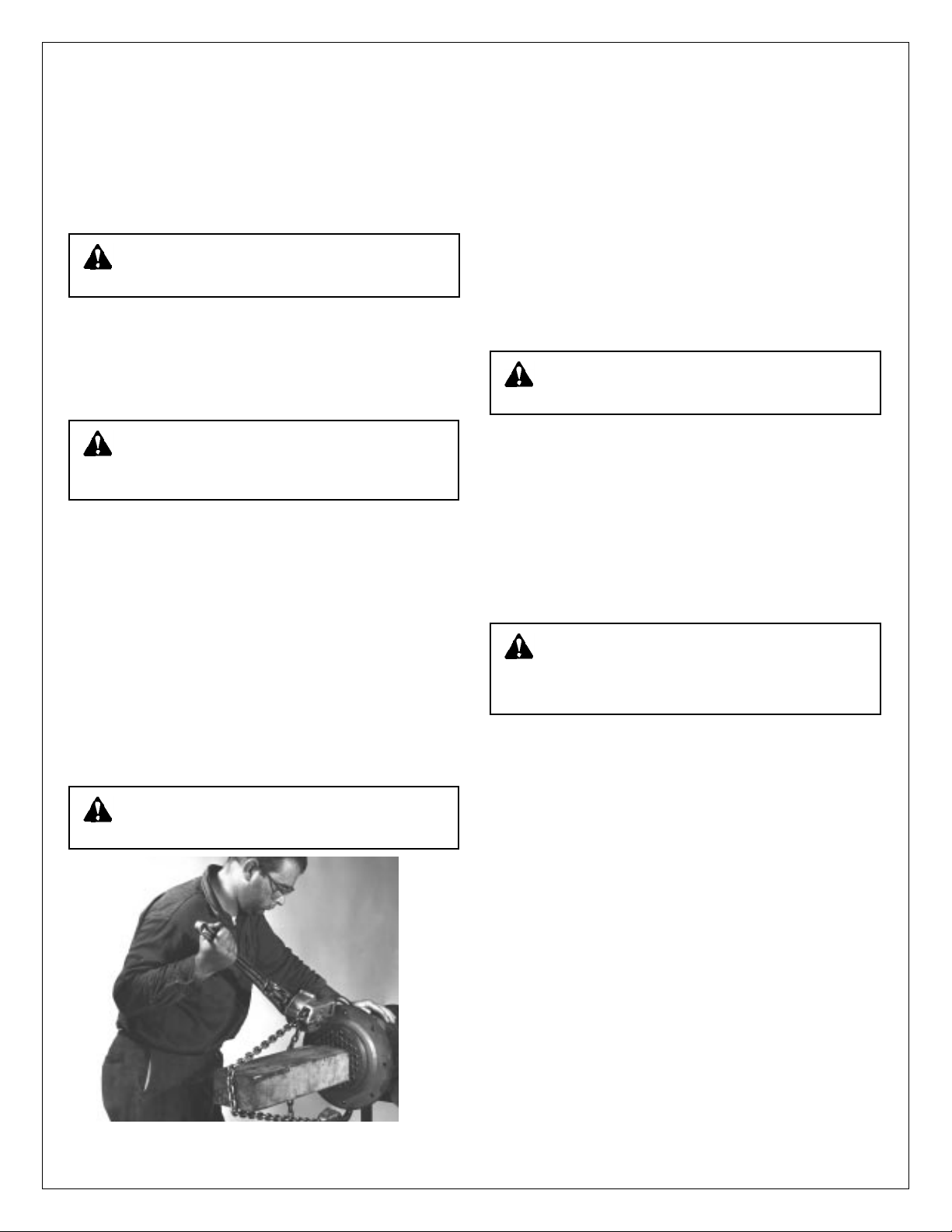
Illustration No. 1 – The method employed to push tube bundle out
of shell.
Proper precautions must be taken (special
4. To clean or inspect inside of tubes, remove channel cover and
rear head. On exchangers having bonnet type heads (without
channel cover), piping must be disconnected and both heads
removed.
5. Do not attempt to clean tubes by blowing steam through individual tubes. This overheats the tube and results in tube
expansion strains and sometimes leaking tubes.
6. Frequently and at regular intervals, observe interior and exterior condition of all tubes and keep them clean. Frequency of
cleaning should be according to scale build-up.
CAUTION:
Neglect in keeping all tubes clean may
result in complete stoppage of flow through some
tubes with consequent overheating of these tubes, resulting
in severe expansion strains, leaking tube joints, and damage
to the heat exchanger.
7. Exchangers subject to fouling or scaling should be cleaned
periodically. A light sludge or scale coating on the tube greatly
reduces its effectiveness. A marked increase in pressure drop
and/or reduction in performance usually indicates cleaning is
necessary, if the unit has been checked for air or vapor binding and this has been found not to be the cause. Since the difficulty of cleaning increases rapidly as the scale thickens or
deposits increases, the interval between cleanings should not
be excessive.
8. Tube bundle removal:
a. During bundle removal, the dead weight of bundle should
never be supported on individual tubes since the tubes are
small and of relatively thin metal. Rest the bundle on the
tube sheet, support plates, or wood blocks cut to fit
periphery of the bundle.
b. Be sure there is a soft wood filler between ends of tubes
and steel bearing plate when pushing bundle out. On
smaller bundles of 12" diameter and under, it is permissible to use hard wood block in place of wood filler and
steel bearing plates. See Illustration No. 1.
c. Tube bundles may be raised using slings formed by bend-
ing light plates into a “U” form and attaching lifting lugs to
the ends of the sheets. Baffles can be easily bent and damaged if dragged over rough surfaces.
3
Page 4

CAUTION:
Failure to follow the procedures mentioned
in steps 8a, b, and c may result in damage to the tubes
or tube joints leading to premature failure of the heat
exchanger.
9. Removing the tube bundle:
Refer to drawings on pages 6 and 7 giving part names of
models MEAH, OC, GC and ACA. The model MEAH tube
bundles are more difficult to remove than the other models.
The MEAH exchanger has the horizontal baffles (N) extending
from the stationary tube steel (B) to about 5 inches of the
packed floating tube sheet (E). Two rubber baffle strips (O) are
adhered to the horizontal steel baffle (N). The rubber baffle
strips seal the space between the shell and horizontal baffle,
and prevent liquid by-passing. These rubber baffle strips (O)
in the MEAH act as brakes against the shell (C) making bundle
removal more difficult.
a. If the exchanger is difficult to work upon, hoist it into the
open after disconnecting piping.
b. Remove front (A) and rear (F) heads. See Illustration No. 2.
Illustration No. 4 – Prying off retainer rings.
Illustration No. 2 – Removing rear head (completely remove front and
rear heads).
Illustration No. 3 – Cross section of type “OC” Heat Exchanger showing
rear tube sheet construction. (See packing retainer detail)
4
Illustration No. 5 – Marking of tube sheet and shell flange.
c. Remove packing (G) and retaining rings (H). It may be nec-
essary to tap lightly on the retainer rings for starting their
removal. More detail of floating tube sheet is given in Illustration No. 3. Illustration No. 4 shows the method of prying
retainer rings off. If tapping is necessary, be sure to tap
evenly about the circumference so the retainer ring does
not bind on the floating tube sheet.
d. Mark tube sheet (B) and shell flange for later re-alignment.
Illustration No. 5.
e. Use chain jack. One suitable is Coffing Hoist, Model MA-15
3
/4ton capacity. Place short piece of 4x4 hardwood (oak)
between chain of jack and floating tube sheet (E). See
Illustration No. 1. Use longer 4x4 pieces as bundle is
removed. Support the bundle by lifting or resting on the
stationary tube sheet (B), as bundle is pushed out. Illustration No. 6.
Page 5

10. Replacing the tube bundle:
The tube bundles for models ACA, GC, MEA, MEAH and OC
(the packed floating tube sheet units) can be replaced using
the tools and reverse procedure given for bundle removal.
Usually, the bundles ACA, GC, MEA and OC, can be shoved
back into the shell (C) manually without the use of the chain
jack.
It may be necessary to use the chain jack when replacing
MEAH bundles.
CAUTION:
Model MEAH (which has the long steel hor-
izontal baffle (N) with the rubber baffle sealing strips (O)
adhered to the horizontal baffle):
The rubber baffle strips (O) are sealing strips between the shell (C)
and horizontal baffle (N). The rubber baffle strips (O) must curl
along the shell (C) towards the shell’s liquid inlet connection. The
liquid pressure forces the rubber baffle strips against shell and
seals it. This is shown in Illustration No. 7.
Illustration No. 6 – Removal of tube bundle showing method of tube bundle support.
NOTE: When replacing heads use a torque wrench.
a. On heads (front heads) with gaskets, tighten
to 40 ft. lbs. and
5
/8" diameter bolts to 80 ft. lbs. If the gasket
1
/2" diameter bolts
joint still leaks, tighten in 5 ft. lbs. increments until leak stops.
b. On heads with packing (rear heads), tighten initially to 50 ft.
lbs. If the packing still leaks tighten in 5 ft. lbs. increments until
leak stops. Do not exceed 100 ft. lbs. on the bolts for the
packed heads.
*The above torque values apply to well lubricated nut bearing
surfaces.
All bolted joints should be tightened uniformly and in a diametrically staggered pattern as illustrated below:
START
1
6
9
14
4
7
12
16
11
8
3
13
10
5
2
15
BUNA STRIP
(Must curl upward
as shown)
LIQUID INLET
Illustration No. 7 – Position of rubber baffle strips and liquid inlet in
relation to each other when assembling unit.
5
Page 6

B
LIQUID OUTLET
FOR MEAH
A K
J
J
1. When ordering give complete nameplate data and part name.
2. Types OC, GC and ACA have no horizontal steel baffle.
A – FRONT HEAD
B – STATIONARY TUBE SHEET
C – SHELL
D – SADDLES
E – PACKED FLOATING TUBE SHEET
F – REAR HEAD
G – PACKING
H – PACKING RETAINER RING
(SEE PACKING RETAINER DETAIL)
ONLY MODELS MEAH HAVE HORIZONTAL BAFFLES.
M
D
P
MODELS MEAH, OC, GC AND ACA HEAT EXCHANGERS
N
O
C
PARTS LIST
(BONNET HEAD)
L
LIQUID INLET FOR
OC, GC AND ACA
J – HEAD CONNECTIONS
K – SHELL CONNECTIONS
L – RELIEF VALVE OPENING
M – DRAINS
N – HORIZONTAL STEEL BAFFLE
O – RUBBER BAFFLE STRIPS
P – VERTICAL SEGMENTAL BAFFLES
(TYPE MEAH ONLY)
(TYPE MEAH ONLY)
M
6
G
H
E
F
Page 7

PACKING RETAINER DETAIL
BONNET
BONNET
PACKING RING
(3 RINGS REQ.)
PACKING RETAINER RING
WEEP
HOLE
SHELL
ASSEMBLY
TUBES
3" UNIT DIAMETER ONLY
PACKING RETAINER
RING ASSEMBLY
SHELL
ASSEMBLY
BONNET OR
CHANNEL
ASSEMBLY
PACKING RING
(4 RINGS REQ.)
PACKING RING
(4 RINGS REQ.)
PACKING RETAINER
RING (ONE PIECE)
TUBES
UNIT DIAMETER 4" THRU 12"
(TWO PIECE PACKING RETAINER
WEEP
HOLE
SHELL
ASSEMBLY
TUBES
UNIT DIAMETER 14" THRU 30"
(ONE PIECE PACKING RETAINER
7
Page 8

MODEL OC
THIS TWO PASS TYPE OF MODEL OC IS REPRESENTATIVE
OF THE MODELS MEA, ACA, GC AND MEAH
FRONT
HEAD
HEAD
GASKET
TUBE BUNDLE
(PARTIALLY REMOVED)
TANK
GASKET
When ordering replacement parts give names of
part, catalogue and factory number from nameplate.
NAMEPLATE
SHELL ASSEMBLY
ADJUSTABLE STEEL
SUPPORT LEGS
PACKING
(ONE SET
NEEDED)
PACKING RETAINER RING ASSEMBLY
WITH SQUARE BAR STOCK SEPARATOR
REAR HEAD
PACKING
RETAINER RING
INSTRUCTIONS FOR INSTALLATION OF RUBBER BAFFLE STRIPS
(Horizontal Baffle Seals)
The following is the procedure for installing rubber strips on MEAH
heat exchanger tube bundles:
1. After removing the tube bundle from the casing, remove old
strips and tie down plate at stationary tube sheet. (Tie down
plate is not on all models.)
2. Remove all grease and dirt and clean to bare metal.
3. Apply a one inch wide coat of adhesive to both the steel baffle
and the rubber baffle strips. (Bell & Gossett uses Barge
cement.)
For further information, contact Bell & Gossett Heat Transfer Products, 175 Standard Parkway, Cheektowaga, NY 14227,
Phone (716) 862-4171 — Facsimile (716) 862-4176.
PRINTED IN U.S.A. 5-95
4. After the adhesive becomes “tacky,” press the rubber strip
firmly into place. Make sure the strip is flush against the stationary tube sheet.
5. Allow the adhesive to set up for about one hour, replace the tie
down plate and replace the tube bundle into the casing.
Bell & Gossett
Morton Grove, IL, U.S.A.
 Loading...