

Page 1
INSTRUCTION MANUAL
HS-801
REVISION D
Hoffman Specialty
®
Replacement Cover
Assembly for Series
600, 601, 602, 603 and
604 and Internal Parts &
Kits for 616/B6 Inverted
Bucket Steam Traps
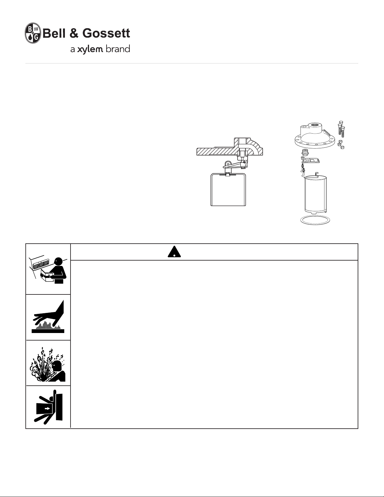
Series 600 Inverted Bucket Trap
Replacement Cover Assembly
WARNING
CAUTION
WARNING
• Before using product, read and understand instructions.
!
616/B6 Cover and Internal Parts
• Save these instructions for future reference.
• All work must be performed by qualified personnel trained in the proper application,
installation, and maintenance of steam systems in accordance with all applicable codes
and ordinances.
• To prevent serious burns, the internal pressure of the trap must be 0 psi (0 bar) before
servicing.
• To prevent serious burns, wear heat resistant gloves when opening and closing steam
valves, or handling hot equipment.
• To prevent serious personal injury from steam pipe blow down, connect a temporary
pipe between the steam pipe opening and a drain, or stand at least 100 ft. (30m) from
the front of the pipe opening.
• To prevent property damage, personal injury, or death, cap off the gate valves if they
are not connected to a drain and when they are not in use for test or pressure relief.
Failure to follow this warning could cause property damage, personal injury or death.
IMPORTANT: To prevent system damage from water
hammer or sudden shock, open supply valves slowly.
If you are uncertain about the product’s adaptability for
your application, please call the factory or authorized
representative before using the product.
The trap seat rating (stamped on the nameplate) must
be equal to or greater than the maximum system
pressure.
Page 2
INSTALLATION –
TOOLS NEEDED:
One (1) socket or open-end wrench and one (1) scraper.
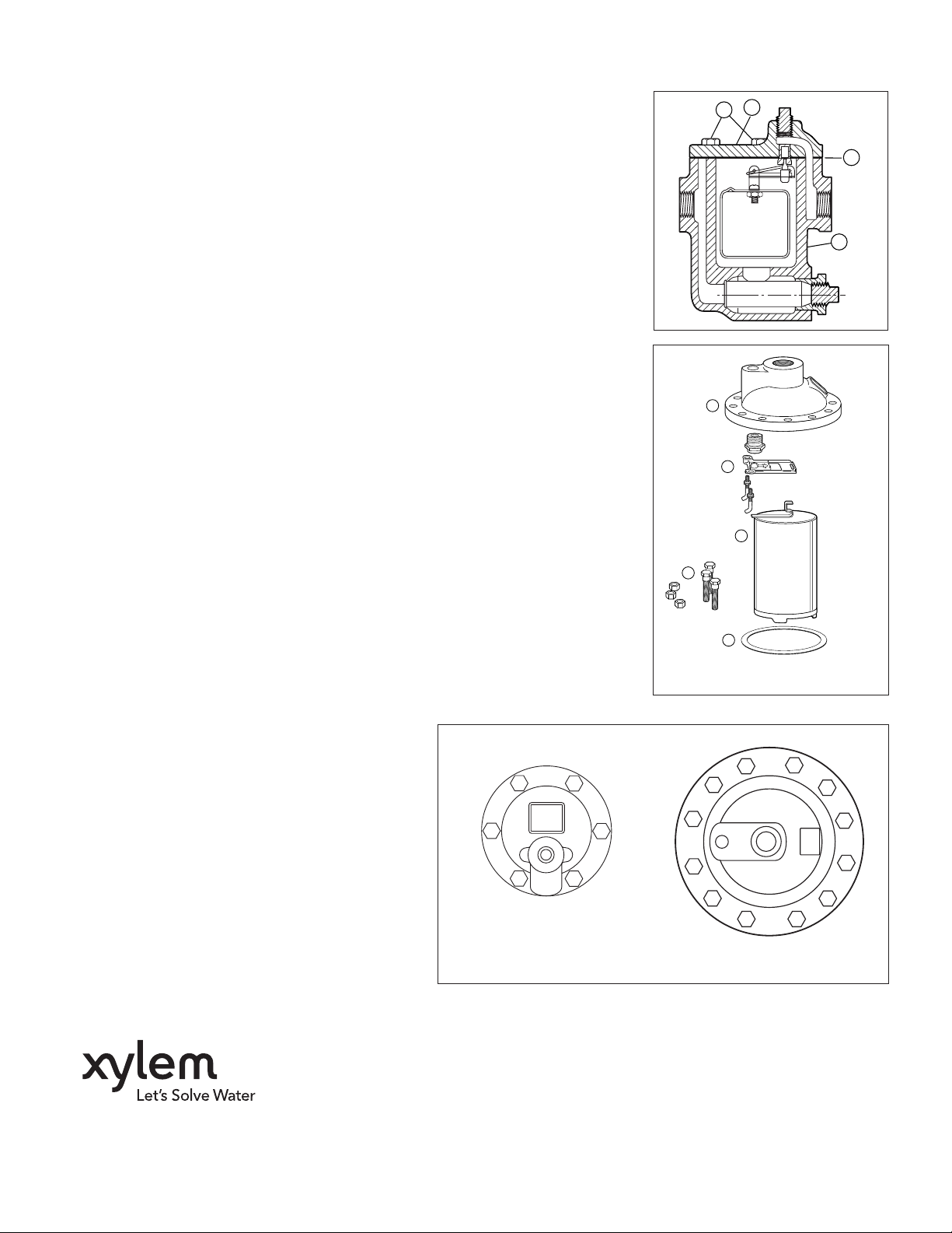
Series 600 through 604 Replacement Cover Assemblies
• Using wrench, loosen and remove cover assembly bolts (A).
• Remove cover assembly (B) and internal parts.
• Using scraper, remove gasket (C).
• Clean body gasket surface and inspect and clean body bowl (D).
• Install cover gasket.
• Install cover assembly with internal parts attached and hand tighten
cover assembly bolts (A). Using wrench or socket, tighten cover
assembly bolts (A) in pattern illustrated below.
• Prime trap before putting in service.
Series 616 and B6 Replacement Internal Components
• Using wrench, loosen and remove cover assembly bolts and nuts (J).
• Remove cover assembly and internal parts (E, F, H) together from the body.
• Clean the gasket surfaces of the body and cover using a scraper; in normal
maintenance, inspect and clean the interior of the body. Replace gasket (G).
• For internal parts (F) replacement, remove the bucket assembly (H) from the
lever. Loosen the nuts of the guide pins that hold the lever assembly. Turn the
guide pins (note orientation of the bend on the end of the pin) so the lever
assembly will come off the pins. Remove the pins. Remove the seat from the
cover.
• Install the new seat and tighten securely. Install the guide pins with the locking
nuts into the cover to a height of 1 9/32" (32mm). Orient the bend of the pins
toward the center and parallel to each other, lock in this position by tightening
the nuts against the cover. Position the pre-assembled lever and pin (E) onto
the guide pins. Be sure the lever swings freely and the lever pin moves into
the center of the seat when the lever assembly is approximately parallel to the
surface of the seat. Hook the bucket (H) to the lever through the slot. If old
bucket is reused, be sure bleed hole in top of bucket is clear.
• Place the cover gasket (G) on the body. Position the cover and internal parts
onto the body. Hand-assemble the 12 bolts through the cover and body and
secure the bolts with the nuts and tighten in the pattern shown below.
Retighten them to the torque values in the same pattern.
• Prime the trap prior to returning to service.
Cover assembly bolts must be tightened in numerical order as shown.
Retighten bolts in order to torque values:
Models 600, 601 and 602: 25 lbf•ft (34 N•m)
Models 603, 604, 616 and B6: 30 lbf•ft (41 N•m)
46
PRIMING – After repair or service, bucket traps
must be primed. This can easily be done by one of
two methods:
1.Remove the pipe plug from the trap cover and
fill the body by pouring water through the
tapping above the seat. Replace the pipe plug.
2.Close the downstream valve on the discharge
side of the equipment. When condensate has
filled the body of the trap, slowly open the
valve. The trap will self prime.
1
3
600-604 Series Bolt
Tightening Pattern
2
5
B
A
E
F
H
J
G
B6/616 Internal Parts
12
7
1
5
9
3
B6/616 Series Bolt
Tightening Pattern
C
D
4
10
6
2
8
11
Xylem Inc.
8200 N. Austin Avenue
Morton Grove, Illinois 60053
Phone: (847) 966-3700
Fax: (847) 965-8379
www.xyleminc.com/brands/bellgossett
Bell & Gossett is a trademark of Xylem Inc. or one of its subsidiaries.
© 2012 Xylem Inc. HS-801D October 2012 Part No. 510909
 Loading...