

Page 1
INSTRUCTION MANUAL
HS-619
REVISION B
Hoffman Specialty
®
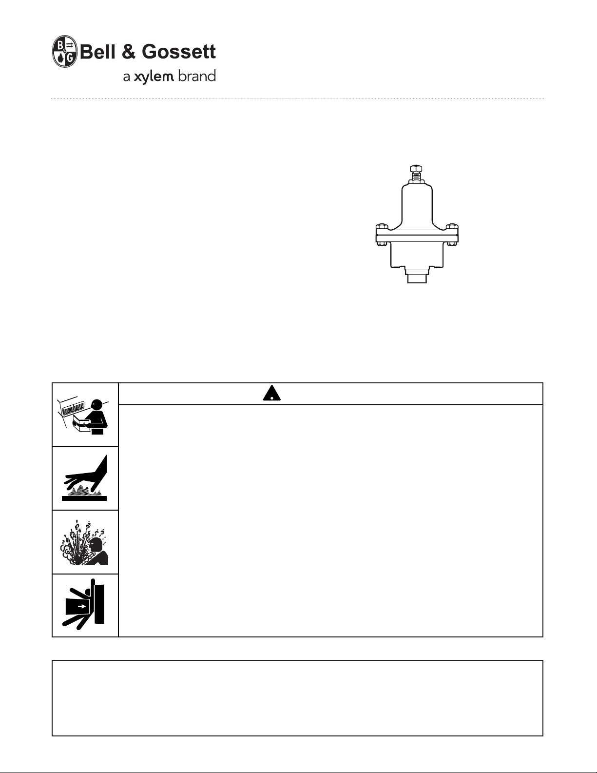
Series 754
Self-Contained Pressure
Reducing Regulator
For Steam Service
Maximum Body Pressure 250 Psig (17.3 bar)
Maximum Temperature 406°F (208°C)
WARNING
CAUTION
WARNING
• Before using product, read and understand instructions.
!
• Save these instructions for future reference.
• All work must be performed by qualified personnel trained in the proper application,
installation, and maintenance of steam systems in accordance with all applicable codes
and ordinances.
• To prevent serious burns, wear heat resistant gloves when opening and closing steam
valves, or handling hot equipment.
• To prevent serious burns, the internal pressure of the regulator must be 0 psi (0 bar) before
servicing.
• Connect a pipe to the blow down valve in such a way as to prevent exposure and injury
from discharge.
• To prevent property damage, personal injury, or death, cap off the gate valves if they
are not connected to a drain and when they are not in use for test or pressure relief.
Failure to follow this warning could cause property damage, personal injury or death.
IMPORTANT: To prevent system damage from water
hammer or sudden shock, open supply valves slowly.
If you are uncertain about the product’s adaptability for
your application, please call the factory or
authorized representative before using the product.
Page 2
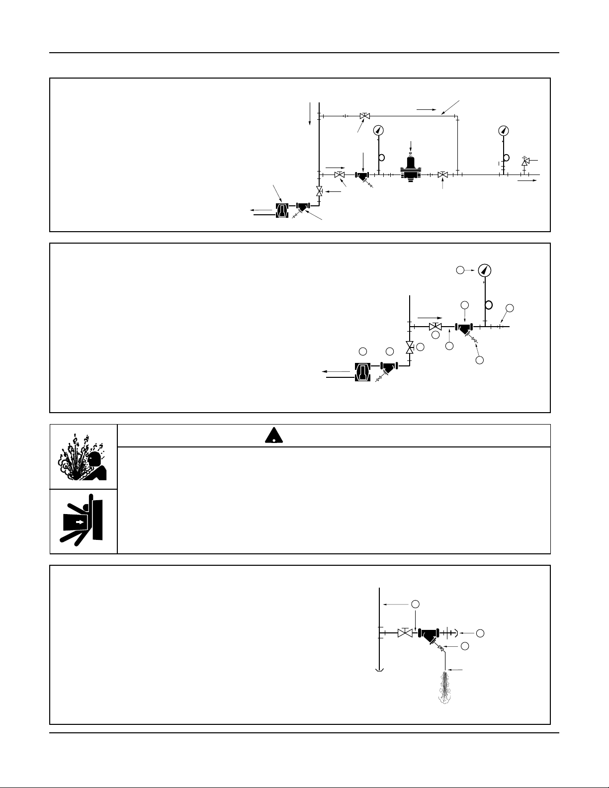
INSTALLATION
Steam
Supply
Globe Valve Recommended
For Throttling Purposes
Optional By-Pass Line
Series 754
Pressure
Reducing
Regulator
By-Pass
Inlet
Relief
Valve
Y Strainer
Y Strainer
F&T
Trap
Gate
Valve
Gate
Valve
1. Determine where to install the regulator, based
on the following requirements:
a. The regulator must be installed where it can
be accessed for adjustment and repair.
2. Install the following ahead of where the regulator
will be installed.
D
a. A drip trap (A), Y-strainer (P) and gate valve
(R). This insures dry steam.
b. A gate valve (C), Y-strainer (H), pressure
gauge (D), and union (E) in the inlet piping
(F).
c. Install a gate valve (G) in the Y-strainer (H)
for blow down.
• To prevent serious burns, the internal pressure of the regulator must be 0 psi (0 bar)
before servicing.
• Connect a pipe to the blow down valve in such a way as to prevent exposure and injury
from discharge.
Failure to follow this caution will cause personal injury.
3a.Cap off the outlet pipe (J).
WARNING
!
H
C
F
A
P
R
G
E
b. Open the Y-strainer’s blow down gate valve (G).
c. Slowly turn steam on with full pressure for five (5)
minutes to blow down the inlet pipe (F).
d. Turn off steam and allow pipe to cool.
e. Remove cap from the outlet pipe (J) and
close the Y-strainer’s blow down gate valve (G).
F
J
G
Pipe Opening
Page 3

Steam
Supply
B
J
F
H
E
D
4a.Position and install the Series 754 Regulator
(B) with the adjusting screw (H) on top.
b. Install a union (E), a gate valve (J), and a
pressure gauge (D) in the outlet piping (F).
5. Optional
Install bypass line (K) with a globe valve (L), for
manual regulation during servicing.
6. Install a steam pressure relief valve (M).
Check to make sure that the set point
is correct:
Systems
Relief Valve Setting
Up to 35 psig At least 5 psi (.35 bar)
(2.4 bar) higher than outlet
pressure.
Over 35 psig At least 10 psi higher
(2.4 bar) than higher than outlet
pressure.
Steam
Supply
Steam
Supply
L
C
K
N
J
M
7. Check to make sure that the adjusting screw
(N) is backed out counterclockwise to relieve
spring tension. Slowly open gate valve (C)
and observe for leaks.
8. Slowly open the outlet gate valve (J). Turn
the adjusting screw (N) clockwise to increase
pressure to the set point. Allow the system to
stabilize. When set, tighten the regulating
screw locknut.
INSTALLATION COMPLETE
Page 4

MAINTENANCE
!
TROUBLESHOOTING
SCHEDULE:
• Initially, every 2-3 days after start-up until system
is clean.
• Every 6 months thereafter.
PROCEDURE:
WARNING
• To prevent serious burns, the
internal pressure of the regulator
must be 0 psi (0 bar) before
servicing.
• Connect a pipe to the blow
down valve in such a way as to
prevent exposure and injury from
discharge.
Failure to follow this caution will
cause personal injury.
We recommend replacing the Series 754
Regulator when parts no longer operate
properly. A new regulator is more economical
than repairing or replacing individual parts, and it will
provide greater reliability.
Problem:
1. Inadequate outlet pressure.
a. Cause: The regulator is not adjusted properly.
Solution: Loosen the locknut on the adjusting
screw and turn it counterclockwise.
b. Cause: Dirt in the strainer.
Solution: Open the Y-strainer’s blow down gate
valve and allow full steam pressure to
flow for two minutes.
c. Cause: Steam supply pressure is low.
1. Inspect joints for leaks. Stop all leaks by tightening
bolts.
2. Clean strainers by opening the
blow down gate valve
pressure to flow out for (2) two minutes. Then,
close the valve.
3. If steam escapes from the vent hole in the spring
housing area, replace the diaphragms.
and allowing full steam
Y-strainer’s
Solution: Correct boiler steam pressure
problem.
d. Cause: Dirt under the seat, or the seat is
worn.
Solution: Disassemble regulator and inspect,
replace if necessary.
Xylem Inc.
8200 N. Austin Avenue
Morton Grove, Illinois 60053
Phone: (847) 966-3700
Fax: (847) 965-8379
www.xyleminc.com/brands/bellgossett
Bell & Gossett is a trademark of Xylem Inc. or one of its subsidiaries.
© 2012 Xylem Inc. HS-619B October 2012 Part No. 511140
 Loading...