

Page 1
INSTRUCTION MANUAL
!
HS-601
REVISION G
Hoffman Specialty
®
Pilot Operated Pressure and/or
Temperature Steam Regulators
Series 2000
WARNING
CAUTION
• Before using product, read and understand instructions.
• Save these instructions for future reference.
• All work must be performed by qualified personnel trained in the proper application,
installation, and maintenance of steam systems in accordance with all applicable codes
and ordinances.
• To prevent serious burns, wear heat resistant gloves when opening and closing steam
valves, or handling hot e
• To prevent serious personal injury from steam pipe blow down, connect a temporary
pipe between the steam pipe opening and a drain, or stand at least 100 ft. (30m) from
the front of the pipe opening.
• To prevent property damage, personal injury, or death, cap off the gate valves if they
are not connected to a drain and when they are not in use for test or pressure relief.
Failure to follow this warning could cause property damage, personal injury or death.
quipment.
WARNING
Page 2

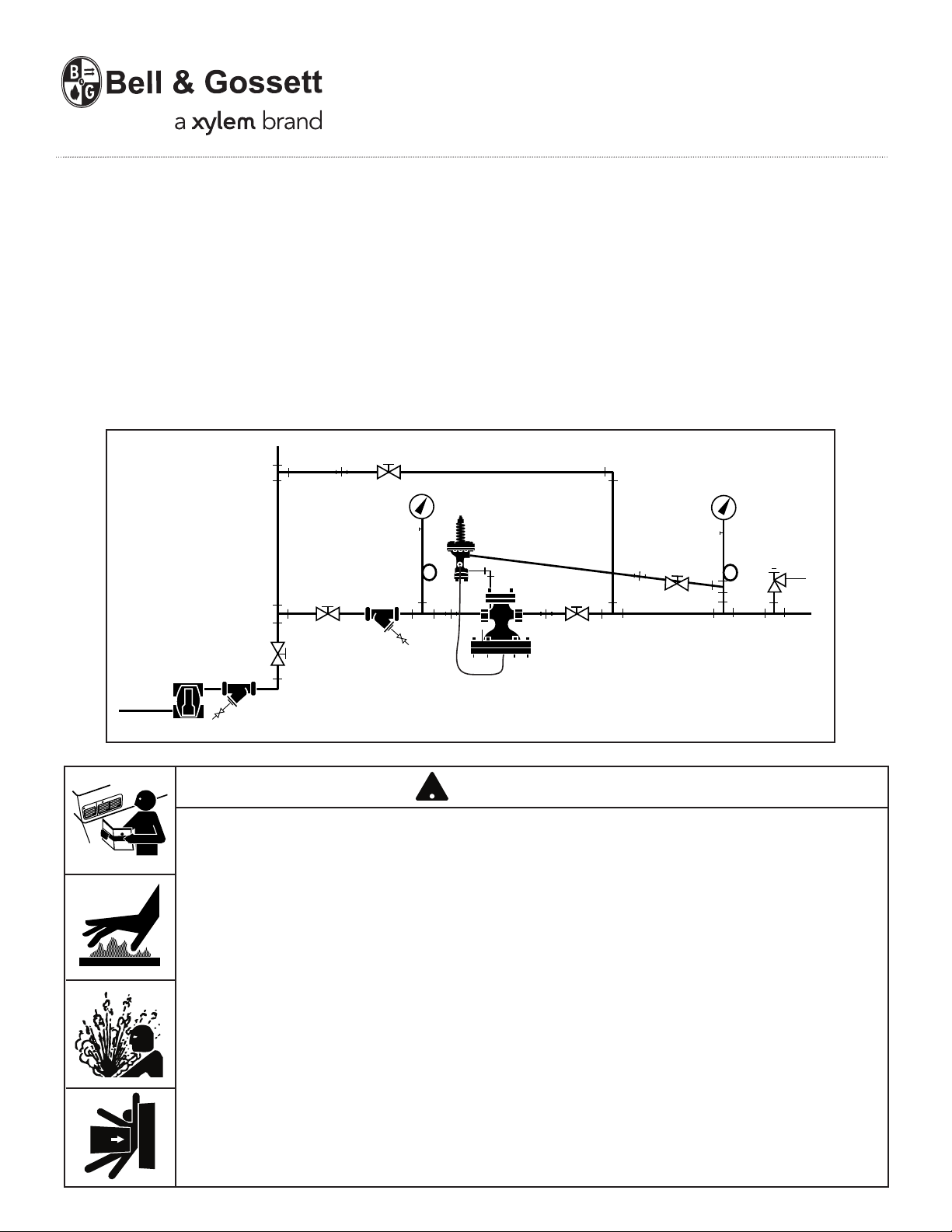
PLANNING THE INSTALLATION
Planning for the Main Valve Installation
1. The regulator main valve must be located in an
accessible straight run of horizontal piping.
OTE: Main valve must be installed with diaphragm
N
located on bottom, as shown in Main Valve Installation
illustration, page 3.
2. Allow clearance on top of the main valve to remove
the cover plate to inspect and service the valve.
3. Allow clearance under the main valve diaphragm
cover to replace diaphragms and drop out the stem
for service.
4. Piping should be sized per good engineering practice.
HVAC applications generally use 6,000 FPM velocity.
Industrial applications generally use 8,000 to 10,000
FPM.
5. Blow out all piping with steam or compressed air before
installing the main valve to remove mill scale and dirt.
6. Use long radius elbows in the low pressure piping.
Avoid the use of bull-headed tees.
7. Provide a bypass line with a globe valve to allow
inspection without interrupting service.
8. Install pressure gauges on inlet and outlet sides of
regulator to indicate system performance.
9. Install drip traps to prevent:
• Accumulation of condensate that can cause water
hammer and destroy the main valve and pilot
diaphragms.
• Slow response times that cause temperature or
pressure fluctuations.
10. Install "Y" Strainers in steam lines with the dirt pocket
turned to the side to prevent collection of condensate
that can be carried into the regulator and cause water
hammer.
11. Install pressure relief valves in accordance with local
nd national codes. The relief valve must be capable
a
of passing the full capacity of the regulator with its
largest seat trim.
Select the relief valve opening set point pressure
ased on the downstream pressure from the regulator.
b
The actual relief valve set point pressure depends on
the relationship of the flow (load) to the main valve
rated capacity.
For systems with spring or air pilots:
Determine the relief pressure set point pressure for
systems as follows:
Downstream Flow Relief valve
System (Load) opening set
Pressure (DSP) Condition point pressure
< 35 psig < 50% of capacity DSP + 5 psig
< 35 psig ≥ 51% of capacity (1.1 x DSP) + 5 psig
≥36 psig < 50% of capacity DSP + 10 psig
≥36 psig ≥ 51% of capacity (1.1 x DSP) + 10 psig
For systems with temperature pilots only:
The steam system relief valve opening set point
pressure is based on the supply steam inlet pressure
to the regulator and must be set as follows:
Supply Steam Relief valve
Inlet Pressure opening set
(SSIP) point pressure
< 35 psig SSIP + 5 psig
≥36 psig SSIP + 10 psig
12. Locate temperature regulators close to the temperature
sensing location. The temperature pilot capillary tube
must allow the sensing bulb to be fully inserted into
the system fluid.
Planning for the Pilot Installation
1. The pilot valves can be installed on either side of the
main valve. The main valve is shipped with the U-tubing
and the bleed orifice installed for left-hand side
mounting of the pilot valves. (U-tubing is mounted on
the right-hand side and the bleed orifice is installed
on the left-hand side.)
If right-hand side mounting of the pilot(s) is desired,
the U-tubing and the bleed orifice must be relocated
to the opposite sides of the main valve.
Note: Right-hand side and left-hand side positioning
is determined when the main valve inlet directly faces
the observer.
2. Determine which pilot(s) are to be used for the installation. Multiple pilots can be used in combination on
one main valve. Mount the pilot(s) as follows:
• SLD Solenoid Pilot
Always mount closest to the main valve.
2
• SPS Spring or AP Air Pressure Pilots
When used in combination with other pilots,
always mount spring or air pilots furthest from
the main valve.
• STPA Temperature Pilot
When used with pressure pilot mount closest to
main valve.
When used with pressure and solenoid pilots –
mount between pressure and solenoid pilots.
• 315 PNT or 240PNT Pneumatic Temperature
Pilots
Mounted remotely from main valve.
• GT610-IP Electronic Pilot (used with customer
supplied temperature sensor and controller)
Mounted remotely from main valve.
3. Hardware kits containing steel pipe nipples and
copper tube lines are required to mount the pilots.
Refer to "Mounting Hardware for Pilot Installation"
Page 4.
Page 3
N
10 Pipe
Diameters
O
M
H
F
G
E
J
L
P
R
S
Z
Y
X
W
U
V
T
B
A
C
K
D
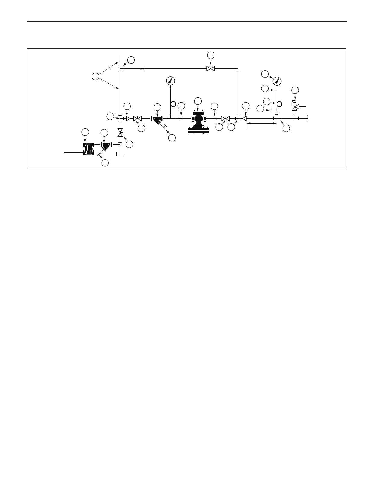
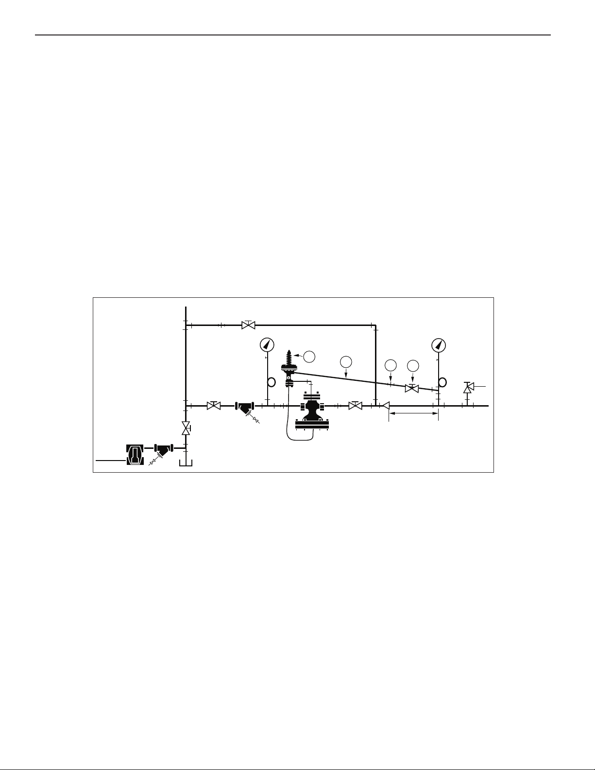
INSTALLATION DETAIL
Main Valve Installation
1. Connect a steam line (A) from the steam supply to the
area where regulator valve is to be located. Install tee
fittings (B) for a bypass line, and (C) for the regulator
line.
Note: Drip traps prevent condensate from collecting in
the piping during light loads or when the regulator is
closed. Collected condensate in the piping ahead of
the regulator can cause water hammer when the
regulator opens.
2. Install a shut off valve (E) to allow servicing the trap.
3. Provide a dirt pocket ahead of the strainer to allow
large solids to drop out.
4. Install a drip trap (H), Y-strainer (F) equipped with a
screen and blow down valve (G).
5. Cap the blow down valve outlet to prevent steam
discharge due to accidental opening of valve.
6. Connect a horizontal pipe from tee (C).
7. Connect a reducer (D), if required, to reduce the
steam line to the pipe size of the main valve.
Use additional reducers when the pipe needs to be
reduced more than two pipe sizes. When noise is a
concern, reducers should not have more than a 15
degree taper.
8. Install shut off valve (J) and Y- strainer (K). Turn the
strainer so that the screen is horizontal to prevent
condensate from collecting in the screen pocket.
Condensate pockets can carry with the steam flow,
causing water hammer that can destroy the main
valve diaphragms.
9. Install a strainer blow down valve (L).
10. Cap the blow down valve outlet to prevent steam
discharge due to accidental opening of valve.
11. Install tee, siphon loop tube, petcock, and pressure
gauge.
On NPT sized regulator valves, install a pipe union (M)
12.
to allow regulator removal for service or replacement.
13. Use compressed air or steam to clean piping before
installing the regulator.
• Cap off the end of the steam line.
• Remove caps from the strainer blow down
valves (G) and (L).
• Turn on the steam or air to full pressure and allow
it to blow down for five minutes.
• Close off compressed air or steam.
• Allow piping to cool below 100˚F.
• Reinstall end of line caps on blow down valves.
• Remove cap from end of the steam line.
14. Install main valve (N) with the direction arrow pointing
to the low-pressure side outlet piping.
NPT sized regulator valves:
• Use pipe sealant on male threads only, keeping the
sealant out of the system.
• Use a wrench on the flats of the body to tighten
the joint.
• Use the wrench on the side of the body that is being
tightened to prevent stress and distortion on the body.
Flanged regulator valves:
• Inspect flange surfaces and gaskets.
• Tighten flange bolts using a star pattern. Uneven
bolting may cause steam leakage.
15. Install silencer orifice plate (when used) immediately
after the main valve:
NPT sized regulator valves: Install orifice plate
between two ASME flanges.
Flanged regulator valves: Install the orifice plate
between the valve flange and the outlet pipe flange.
16.
On NPT sized regulator valves, install a pipe union (O)
to allow regulator removal for service or replacement.
17. Install gate valve (P).
18. Install pipe tee (R) for bypass connection.
3
Page 4
19. Install the bypass piping and globe valve (T).
1
2
4
3
5
1076
1
9
4
8
5
10
76
• Use the same size pipe for the bypass piping and
globe valve in the bypass line as the main valve (N)
to allow manual regulation during service of regulator.
Support piping to remove any stress from the
•
regulator valve body before connecting to the system.
• Make sure pipes and flanges are properly aligned to
revent stress on the regulator valve body.
p
20. Install pipe reducer (S) to increase the pipe size, if
necessary, to meet the velocity requirements.
Use additional reducers when the pipe needs to be
increased more than two pipe sizes.
21. Install a 1/4 NPT pipe tapping (U) at least 10 pipe
diameters downstream in a straight run of the
enlarged pipe for the pressure gauge and feedback
line (for spring and/or air pilots) connection.
PILOT INSTALLATION
Mounting Hardware for Pilot Installation
Note: For heat exchanger shell applications, it is
recommended that the feedback line and pressure
gauge be installed directly into the heat exchanger
shell.
22. Install pressure relief valve (V) in the downstream
iping as required by codes.
p
23. Install a tee fitting (W) for pressure feedback line.
4. Install a siphon loop tube (X), petcock (Y) and
2
pressure gauge (Z) in vertical port of tee fitting (W).
25. Connect system piping to complete the installation.
26. Refer to "Pilot Installation" for pilot mounting and
piping instructions.
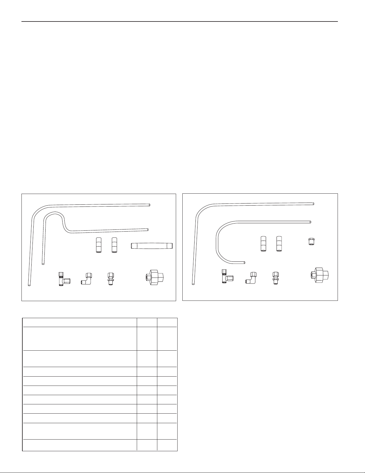
Kit A – For spring or air pilots only or in combination with
temperature or solenoid pilots.
Kit B – For temperature pilot or solenoid pilot only.
Hardware Kit Components
No Part Description Kit A Kit B
1 L-Tubing; from main valve bottom XX
Elbow connection to tee fitting
Branch connection.
2 S-Tubing; from bleed orifice fitting X
to tee fitting on pilot.
3 Nipple, 1/4 NPT x 4" (101mm) X
4 Nipple, 1/4 NPT x 1-1/2" (38mm) (2) XX
5 Union Connection, 1/4 NPT Female XX
6 Tee fitting XX
7 L-fitting XX
8 Bushing X
9 J-Tubing; From bleed orifice fitting X
to tee fitting on pilot.
10 1/8" Tubing connector XX
4
Page 5
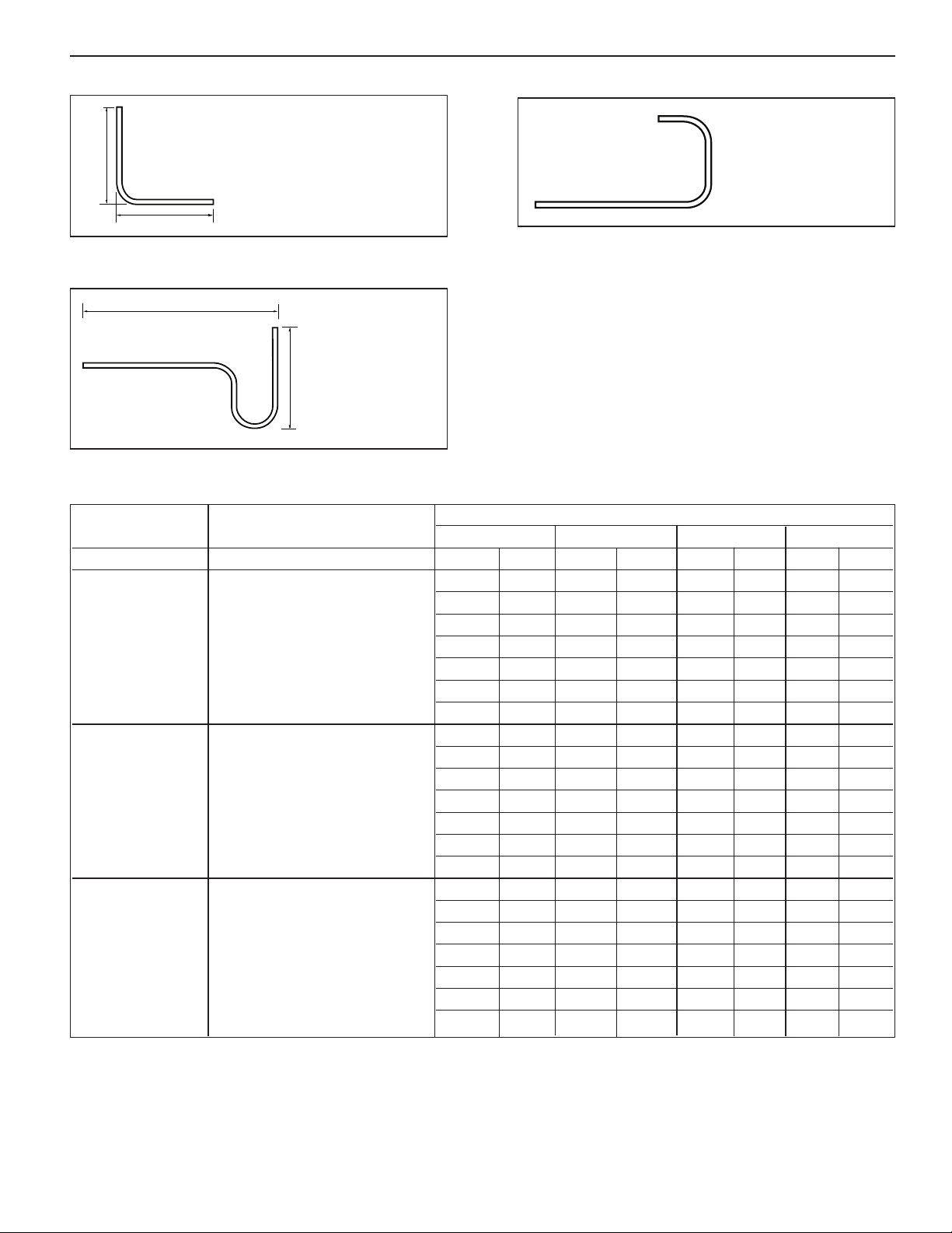
1. L-Tube
C
D
A
B
Cut L- tube to appropriate A & B
dimensions listed on Tubing Length
chart.
No cutting is required if dimension is
marked with an *.
9. J-Tube
No cutting of J-tubes
s required
i
2. S-Tube
Cut S- tube to appropriate C & D dimensions listed on
Tubing Length chart.
No cutting is
required if dimension
is marked with an *.
Tubing Length
DIMENSIONS
ABCD
PILOT MAIN VALVE SIZE In mm In mm In mm In mm
1/2 NPT, 3/4 NPT, 1 NPT 6.0 152 7.6 178 6.4 163 3.5 89
1-1/4 NPT, 1-1/2 NPT 6.8 173 8.1 206 6.4 163 4.8 122
2 NPT, 2 (50) * 8.6 218 8.2 208 6.4 163 * 5.7 145
Spring or Air 2-1/2 (65) 10.6 269 9.1 231 6.4 163 5.9 150
3 (80) 11.2 284 9.4 239 6.4 163 6.4 162
4 (100) 13.0 330 10.3 262 6.4 163 7.9 200
6 (150) *16.6 422 12.3 312 6.4 163 * 9.5 241
1/2 NPT, 3/4 NPT, 1 NPT 6.0 152 11.3 287 *10.0 254 3.5 89
1-1/4 NPT, 1-1/2 NPT 6.8 173 11.7 297 *10.0 254 4.8 122
2 NPT, 2 (50) * 8.6 218 * 11.9 302 *10.0 254 * 5.7 145
Combination 2-1/2 (65) 10.6 269 12.8 325 *10.0 254 5.9 150
Pilots 3 (80) 11.2 284 13.1 333 *10.0 254 6.4 162
4 (100) 13.0 330 13.9 353 *10.0 254 7.9 200
6 (150) *16.6 422 * 14.9 378 *10.0 254 * 9.5 241
1/2 NPT, 3/4 NPT, 1 NPT 5.2 132 7.9 200
1-1/4 NPT, 1-1/2 NPT 6.0 152 8.6 218
2 NPT, 2 (50) 7.8 198 8.8 223
Temperature 2-1/2 (65) 9.8 249 9.7 246
3 (80) 10.4 264 10.0 254
4 (100) 12.2 310 10.9 277
6 (150) 15.8 401 12.0 305
* No cutting of tube length is required.
5
Page 6
A
D
10 Pipe
Diameters
C
B
Bleed Orifice
The function of the bleed orifice is to bleed steam off the
ain valve diaphragm when the pilot(s) close(s). A 1/16"
m
(1.6mm) diameter orifice is standard, and is installed in
he outlet side of the main valve when shipped. This
t
diameter orifice is used in most applications.
In special situations, the bleed orifice may be drilled out
to 3/32" (2.4mm) diameter to produce faster closing time
of the main valve and thus improve response time.
• A 3/32 in. (2.4mm) diameter orifice should NOT be
used in conjunction with a temperature pilot, as
accuracy of temperature control will be reduced.
Pilot Installation Detail
• Typical applications for 3/32 in (2.4mm) diameter
leed orifice may include:
b
– Pressure differential across the reducing valve is
0 psig (3.5 bar) or greater.
5
– High pressure PRV on a 2-stage pressure
reducing station.
– Pressure reducing valve with a fast acting
pneumatic temperature regulator downstream
of the main valve.
Applies to All Pilots
1. The pilot valve(s) can be installed on either side of the
main valve. The main valve is shipped with the U-
tubing and the bleed orifice installed for left-hand side
mounting of the pilot valve(s). If right-hand side
mounting of the pilot(s) is desired, the U-tubing and
the bleed orifice must be relocated to the opposite
sides of the main valve.
Note: Right-hand side and left-hand side positioning is
determined when the main valve inlet directly faces
the observer.
2. Make sure the bleed orifice is installed in the 1/8 NPT
tapping on the outlet end of the main valve on the
opposite side from the U-tubing. Remove the 1/8 NPT
pipe plug from the bleed orifice and replace it with a
1/8 NPT x 1/4" (6mm) OD tubing, straight compression
fitting (from the hardware kit).
3. Install the 1/4 NPT x 1-1/2" (38mm) nipple and half of
the union connection (from the hardware kit) on the
inlet end of the main valve.
6
Use the 1/4 NPT x 4" (101mm) nipple and the remaining
4.
half of the union connection (from the hardware kit) to
mount the first pilot. Mount additional pilots as
required using 1/4" steel pipe nipples.
5. Install the copper tee fitting (from the hardware kit) in
the 1/8 NPT signal tapping on the side of the last pilot
with the tee pointing down.
6.
Install the L-fitting (from the hardware kit) in the tapping
at the center of the main valve diaphragm cover.
Note: For steps 7 and 8, trim the length of the copper
tubing as required (see "Tubing Length Chart", page
5) to make a neat installation. Be sure to ream the
tube to the full tube diameter after cutting.
7. Install the S- or J-copper tubing (from the hardware
kit) from the tee fitting to the bleed orifice.
8. Install the L- copper tubing (from the hardware kit)
from the bottom of the tee fitting to the L-fitting in the
main valve diaphragm cover.
Page 7
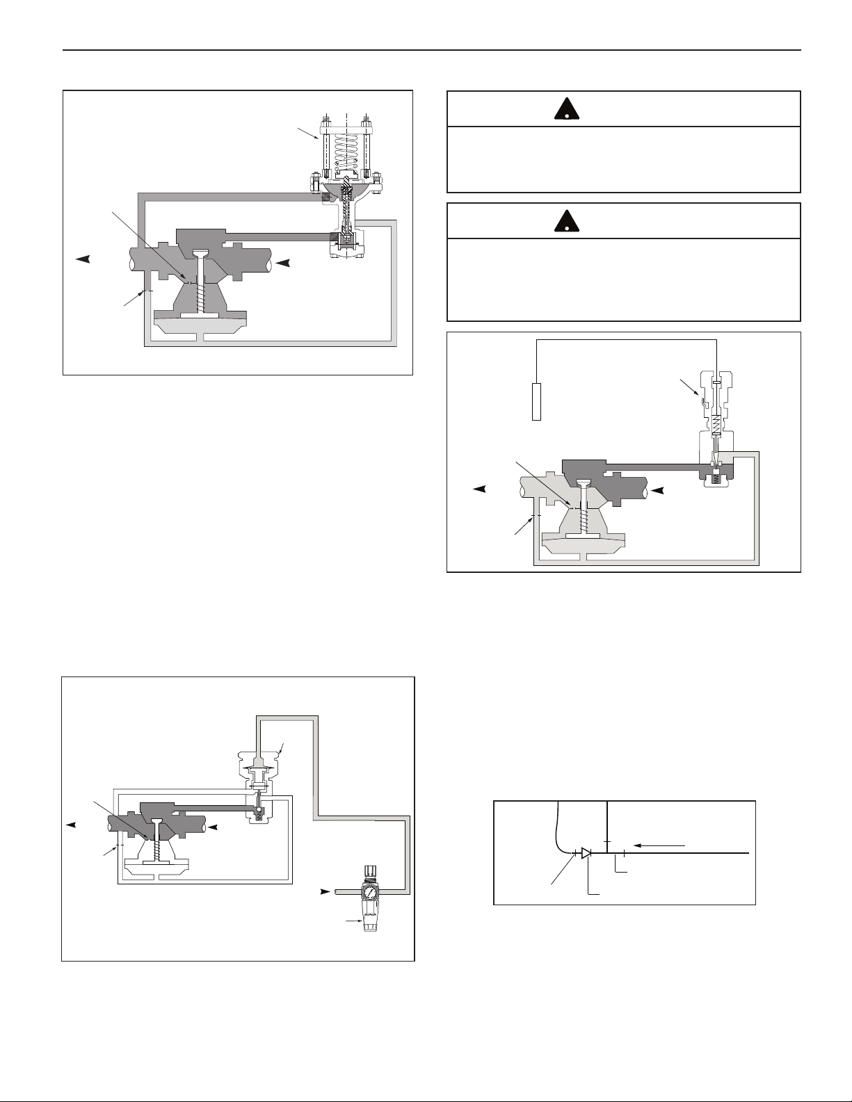
Outlet
Balance
Tube
Bleed
O
rifice
Signal
Feedback Line
Main Valve
Inlet
Pilot Inlet
S
pring
Pilot
Air Supply
Feedback Line
Balance
Tube
Outlet
Bleed
Orifice
Main Valve
Inlet
Pilot Inlet
Signal
AP Air
Pilot
Air PRV
Regulator
High Pressure
Supply Air
T
emperature
S
ensor
Balance
Tube
S
ignal
Temperature
Pilot
Outlet
Bleed
Orifice
Main Valve
I
nlet
Pilot Inlet
Spring/Air Pilots
!
!
Flow from System
Pipe Tee
Pipe Bushing
Sensing Bulb
1. The 1/4" feedback tapping must be connected to the
downstream piping for either a spring or air pressure
pilot:
• Use 1/4 black steel pipe for the feedback line (B).
• Install a 1/4 NPT shut off valve (D) and union (C)
in this line to allow service of the pilot while
operating the system on the by-pass line.
• The feedback line must pitch away from the pilot
to avoid erratic operation, excessive fouling and
eliminate water pockets.
2. When the regulator is used with a heat exchanger,
connect the feedback line (B) to the heat exchanger
shell. A tee fitting can be installed in the heat
exchanger for a vacuum breaker connection.
Temperature Pilots
CAUTION
Temperature pilot bulb will be immersed in the heated
fluid. Before immersing, check compatibility of copper
bulb with heated fluid. Failure to insure compatibility
may cause property damage.
CAUTION
System should be supplied with overheat protection
(such as temperature relief valve or aquastat solenoid
combination) at 10˚F over set temperature. Failure to follow this warning may result in property damage, personal
injury, or death.
1. When only a temperature pilot is used, the outlet
tapping port must be reduced. Use the 1/8 x 1/4
NPT bushing (from the hardware kit) in the 1/4 NPT
outlet.
2. Insert the sensing bulb so the full length of the bulb
is exposed to the fluid whose temperature is being
controlled.
a) Use a 1/2 NPT compression fitting to install the
bulb at the outlet of instantaneous heaters and
in the middle of storage tanks.
b) The preferred bulb mounting when installed in
the system piping is illustrated below:
3. For air pilot installations, connect the regulated air
pressure supply to the top of the pilot bonnet.
c) Optional dry well (separable socket) allows the
sensing bulb to be removed from the tank or
piping without draining the system.
• When using a dry well, coat the bulb with high
temperature grease or heat transfer compound,
to aid heat transfer.
• Make sure that bulb and dry well are fully
inserted into the fluid being controlled.
7
Page 8
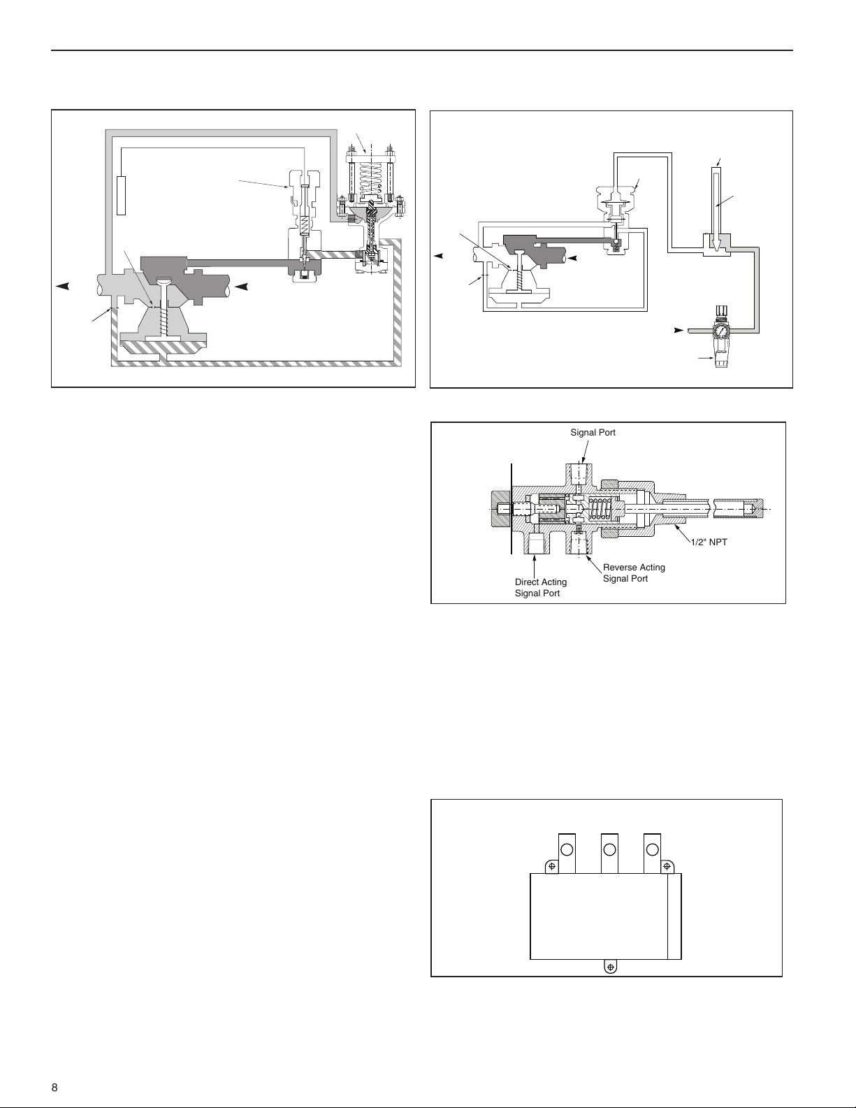
Temperature and Spring Pilot Combination
Spring Pilot
O
utlet
B
alance Tube
S
elf-Contained
Temperature
Pilot
Bleed
O
rifice
Main Valve
I
nlet
P
ilot Inlet
Air Supply
Feedback Line
Balance
Tube
Outlet
Bleed
Orifice
Main Valve
Inlet
Pilot Inlet
S
ignal
A
P Air
Pilot
Temperature
Sensor
315 PNT
T
emperature
Pilot
Air PRV
Regulator
High Pressure
Supply Air
Main
Branch
Supply
Air Port
Branch
Air Port
y
y
y
y
y
y
y
y
y
y
y
y
y
y
y
y
y
yy
yy
yyy
y
Signal Port
Reverse Acting
Signal Port
1/2" NPT
Direct Acting
Signal Port
Pneumatic Temperature and Air Pilot
Combination
1. Install the temperature pilot next to the main valve.
2. Install a 1/4" NPT nipple between the outlet tapping
port of the temperature pilot and the inlet port of the
spring pilot.
3. The 1/4" feedback tapping port of the spring pilot
must be connected to the downstream piping:
• Use 1/4 black steel pipe for the feedback line.
• Install a 1/4 NPT shut off valve and union in the
feedback line to allow service of the pilot while
operating the system on the by-pass line.
• The feedback line must pitch away from the pilot to
avoid erratic operation and excessive fouling and to
eliminate water pockets.
4. When the regulator is used with a heat exchanger,
connect the feedback line (B) (see illustration on
page 6 to the heat exchanger shell. A tee fitting can
be installed in the heat exchanger for a vacuum
breaker connection.
5. Insert the sensing bulb of the temperature pilot so the
full length of the bulb is exposed to the fluid whose
temperature is being controlled.
a) Use a 1/2 NPT compression fitting to install the
bulb at the outlet of instantaneous heaters and in
the middle of storage tanks.
b) The preferred bulb mounting when installed in the
8
system piping is illustrated on page 7.
c) Optional dry well (separable socket) allows the
sensing bulb to be removed from the tank or piping
without draining the system.
• When using a dry well, coat the bulb with high
• Make sure that bulb and dry well are fully inserted
temperature grease or heat transfer compound,
to aid heat transfer.
into the fluid being controlled.
Series 315 PNT Pilot
1. Connect a regulated air supply to the "Reverse
Acting" inlet port of the 315 PNT pneumatic
temperature pilot.
2. Do not plug the "Direct Acting" inlet port of the
pneumatic temperature pilot. This port serves as
an air bleed.
3. Connect the output "Signal" port of the pneumatic
temperature pilot to the top of the AP-1A or AP-4A
pneumatic air pilot.
Series 240 PNT Pilot
1. Connect a regulated air supply to the "Supply Air"
port of the 240 PNT pneumatic temperature pilot.
2. Connect the output "Branch Air" port of the pneumatic
temperature pilot to the top of the AP-1A or AP-4A
pneumatic air pilot.
Page 9

he following chart shows the maximum outlet steam
T
pressure that can be obtained from the main valve. The
outlet steam pressure is based on the air pressure from
PNT Air Signal Maximum Steam Pressure from Main Valve
Outlet Pressure AP-1A Pressure Pilot AP-4A Pressure Pilot
sig Bar psig Bar psig Bar
p
9 (0.62) 0 (0.00) 0 (0.00)
10 (0.69) 1 (0.07) 4 (0.28)
11 (0.76) 2 (0.14) 8 (0.55)
12 (0.83) 3 (0.21) 12 (0.82)
13 (0.90) 4 (0.28) 16 (1.10)
14 (0.97) 5 (0.35) 20 (1.38)
15 (1.04) 6 (0.41) 14 (1.66)
18 (1.24) 9 (0.62) 36 (2.50)
20 (1.38) 11 (1.76) 44 (3.00)
25 (1.73) 16 (1.10) 64 (4.40)
30 (2.07) 21 (1.45) 84 (5.80)
he pneumatic temperature pilot to an AP-1A or AP-4A
t
Pneumatic Pressure Pilot. Intermediate pressures can be
interpolated from the chart.
9
Page 10

SYSTEM START-UP
!
!
. Make sure all strainer blow down valves are closed
1
and capped to prevent accidental burns.
2. Open 1/4 NPT feedback control line shut-off valve.
3. Close inlet valve to main valve. Open outlet gate
valve and all equipment drain valves. Allow system
o drain completely.
t
CAUTION
Never open a reducing valve without positive indication
that the high pressure side is clear of condensate. Be
sure no one is in area of any open end of pipes when
steam is turned on. Failure to follow this caution may
result in serious burns.
4. Make sure bypass globe valve is tightly closed.
5. Release any actuating force on pilot(s).
Spring Close pilot valve by equally unscrewing
adjusting nuts to release compression
on the adjusting spring.
Air Adjust Air PRV Regulator to 0 psig
(0.00 bar)
Temperature Set temperature adjusting knob to the
lowest setting.
NOTE: On STPA-300 and STPA-400 pilots, loosen
the calibration set screw and move the pointer out
the way. Gently turn the adjustment knob clockwise
until the seat is completely closed. This requires that
the pilot be recalibrated, see "Adjusting Temperature
Pilots", page 11.
Solenoid Make sure normally open solenoid is
open or normally closed solenoid is
closed.
6. Slightly open steam supply inlet valve. Open only
enough to allow steam into the system.
7. Apply a small amount of force to the pilots.
Spring Gradually compress adjusting spring
y tightening adjusting nuts equally
b
until the pilot valve opens.
Air Adjust Air PRV to allow pressure to
build slightly until the air pilot valve
opens.
Temperature Increase temperature setting a couple
of degrees at a time.
Pneumatic Dial in temperature and adjust air
Temperature supply pressure to 9 psi (0.62 bar).
8. Allow system to stabilize.
9. Open steam supply inlet valve slightly more. A little
pressure will build on the inlet to the regulator, which
allows it to open and steam to flow.
10. Close all equipment drain valves.
11. Open supply inlet valve more.
12. Allow system to stabilize.
13.
Check for any leaks. Allow time for the piping to heat
up and the drip trap to drain condensate.
14. Slowly allow pressure to build until the inlet gate
valve is about half open. If there are no problems
open inlet gate valve completely.
15. Refer to "Adjusting Pilot(s)", page 11, for final pilot
adjustments.
CAUTION
Hearing protection is required if drain valves are open to
atmosphere. Failure to do so may result in hearing loss.
10
Page 11

ADJUSTING PILOTS
pring/Air Pilots
S
Adjust spring/air pilot to control the system at desired
pressure. The system pressure can be set for full steam
or partial steam flow.
ull Steam Flow – If the spring pilot is adjusted to the
F
required reduced pressure while the system is running at
full steam flow, then the reduced pressure will rise
approximately 10% when the system is running at low
steam flow.
Partial Steam Flow – If the spring pilot is adjusted to the
required reduced pressure while the system is running at
5 – 10% of full steam flow, the reduced pressure will fall
(droop) approximately 10% when the system is running at
full steam flow.
Spring Pilot
1. To increase downstream pressure, increase compression on the adjusting spring by tightening the adjusting
nuts an equal amount.
2. To decrease downstream pressure, release compression on the adjusting spring by loosening the adjusting
nuts an equal amount.
Air Pilot
1. To increase downstream pressure, increase the outlet
pressure from the air regulator. The pilot should open
at approximately 9 psig (0.62 bar).
2. To decrease downstream pressure, decrease the outlet pressure from the air regulator.
Temperature Pilot
1. To increase temperature, loosen Allen lock screw and
turn adjusting knob counterclockwise. Then securely
tighten lock screw.
2. To decrease temperature, loosen Allen lock screw and
turn adjusting knob clockwise. Then securely tighten
lock screw.
3. Once system is running, temperature can be set
immediately.
• Insert a thermometer in heated fluid.
• When thermometer (in heated fluid) indicates
temperature is 5˚F (3˚C) below the required
temperature, turn adjusting knob to lower temperature setting until steam flow stops.
The calibrated temperature dial provides an approx-
•
imate setting. If the temperature dial reading is
slightly off from the thermometer reading, the dial
should be recalibrated, as follows:
Loosen the set screw and turn the indicator and
–
the mounting collar.
Retighten the set screw after making the adjustment.
–
4. Observe the temperature while the system is running.
5. Adjust the sleeve until the desired temperature is
reached.
6. Tighten the dial set screw without turning the adjusting
sleeve.
7. When the temperature setting is complete, use the
Allen head set screw to lock the knob.
Temperature and Spring Pilot Combination
1. With the temperature pilot set to the highest temperature setting, adjust the spring pilot as noted above.
2. Adjust the temperature pilot according to instructions
above.
Pneumatic Temperature and Pneumatic Air Pilot
Combination
With this combination, steam pressure is limited rather
than controlled. The air regulator upstream of the air pilot
and pneumatic temperature pilots controls the air pilot
pressure setting. Through this combination, the air pilot
limits the steam pressure delivered by the main valve.
Therefore, only the temperature is adjusted.
1. The air supply to the PNT pilot should be set between
18 and 36 psig (1.24 – 2.5 bar).
2. Turn the adjusting knob on the pneumatic temperature
pilot to the approximate desired operating temperature.
3. Insert a thermometer in heated fluid.
4. When the thermometer reaches the desired temperature, turn the PNT adjusting knob to indicate 9 psig
(0.62 bar) on the PNT pressure gauge.
5. After conditions have stabilized, make adjustments as
necessary.
For steam pressure limits, refer to "Maximum Steam
Pressure from Main Valve" chart, page 9.
MAINTENANCE
Schedule
1. Initially every 2-3 days after start-up until system is
clean.
2. Every 6 months thereafter.
Procedure:
1. Inspect joints for leaks. Tighten bolts to stop leaks.
2. Open blow down valves on strainers.
3. Allow full pressure steam to pass for two minutes.
4. Close the blow down valves.
5. Observe system pressure and readjust if required.
Control of Pressure and/or Temperature
1. Check to see that operating condition initial adjustments are still set.
2. Consider slightly altering the adjustment to see if the
system responds appropriately.
Solenoid Pilot Actuation
• Make sure solenoid is functioning properly.
Strainers
If screens in Y- strainers or pilot strainers are excessively
•
dirty, system blowdown should be done once a week.
11
Page 12

TROUBLESHOOTING
Replace the regulator or pilot(s) when parts no longer
operate properly. A new regulator is more economical
than replacing individual parts, and will provide greater
reliability.
General Series 2000 Regulator System
Troubleshooting Guidelines
Cause: Main valve undersized.
Solution: Check valve capacity against system load.
Replace with correct size valve.
Cause: Strainer plugged.
Solution: Blow down strainer screen or remove and
clean screen.
Dead End Service
The seat leakage rate for metal single seated valves is
.01% of rated flow, which is the industry standard. In
applications where .01% flow will cause pressure or temperature override, seat lapping may be required. (See
"Seat Lapping Procedure", page 14.)
Lifts in the Return Line on Heat Exchanger
Applications
An elevated return line on a heat exchanger requires
steam pressure to lift condensate. Condensate cannot
drain from the heat exchanger shell until the internal pressure is sufficient to lift the condensate. The steam pressure required to lift the condensate remains in the heat
exchanger shell. This can then cause a temperature
overshoot and wide swings in temperature.
Steam Traps Undersized
Undersized steam traps can cause condensate to back up
in a heat exchanger shell. Backed up condensate covers
some of the tubes, reducing the heat transfer surface. If
condensate backs up it may appear that the regulator is
undersized. When a temperature regulator is installed in
the steam supply, size the steam trap based on 1/2 psig
pressure differential.
Failure to Install System Recirculation Pumps
A system without a recirculation pump will have wide temperature fluctuations during start-up. The regulator will
also overshoot the temperature when system steam flow
stops, trapping steam in the heat exchanger shell due to
the response time required to close the regulator.
Low or Improper Outlet Pressure
Cause: Low inlet pressure
Solution: Correct supply pressure from the boiler.
Fully open supply valve.
Check for upstream blockage.
Cause: The regulator is not properly adjusted.
Solution:
Readjust the pilot to desired operating pressure.
Delivery Pressure High or Overrides
Cause: Bypass valve is open.
Solution: Close bypass valve.
Cause: The regulator is not properly adjusted.
Solution: Readjust the pilot to desired operating
pressure.
Cause: Bleed orifice plugged.
Solution: Clean or replace with new bleed orifice.
Cause: Dirt under the seat of main valve.
Solution: Remove top cover plate and clean the seat
surfaces.
Cause: Pilot valve malfunction.
Solution: Refer to pilot valve test and repair procedures.
Cause: Main valve oversized.
Solution: Check valve capacity against system load.
Replace with correct size valve.
Delivery Pressure or Temperature Erratic
Cause: Pressure momentarily overshoots and then
recedes to set pressure.
Solution: Valve is not responding fast enough to react to
the system. Drilling the bleed orifice out to
3/32" can increase the valve closing response
time. (Do not drill bleed orifice if a temperature
pilot is used, as temperature accuracy will be
decreased. Do not drill bleed orifice if differential pressure across the main valve is less than
40 psi as the valve may not fully open).
Cause: Sensing line improperly located in the system.
Solution: Relocate the sensing line to stable pressure
area.
Cause: Temperature bulb improperly located.
Solution: Relocate sensing bulb to make sure it is fully
inserted into the system flow path.
Cause: Feedback control line plugged.
Solution: Remove and clean.
Cause: Bleed orifice missing or worn.
Solution: Replace with new bleed orifice.
12
Page 13

MAIN VALVE TESTING
All tests can be performed on main valve while it remains
installed in the steam system, if there are gate valves
ocated upstream and downstream of the main valve.
l
1. Isolate the main valve from steam pressure by closing
the gate valves that are located upstream and downstream of the main valve.
2. If the main valve has a spring pilot or air pilot installed
on it, close the shut off valve in the feedback line to
the spring or air pilot.
3. Disconnect the pilot valves from the main valve.
4. Remove the orifice fitting from the 1/8" NPT port
located on the side of the main valve.
Test for Leakage between Plug and Seat:
1. Attach an air line to the 1/4" NPT port located on the
side of the main valve inlet.
2. Apply air to the main valve inlet.
3. Check for air leakage from the 1/8" NPT port on the
side of the main valve outlet.
• Only a small amount of leakage is allowable.
• Excessive leakage indicates either worn seat or
plug, or the seat is held open by dirt.
• Clean seat and plug and retest.
• Replace parts if necessary.
Test for Restricted Movement:
1. Attach an air line containing a pressure regulating
alve (PRV) and pressure gauge to the 1/8 NPT port
v
located in the center of the lower diaphragm case of
the main valve.
2. Disassemble the top cover from the main valve.
3. While adjusting the PRV in the air line:
• Look in the top of the main valve
• Slowly increase and decrease the air pressure to
the lower diaphragm case.
4. Increase and decrease the air pressure several times.
5. Watch the movement of the main valve stem and plug.
6. Check for jerky movement or no movement.
• The valve should stroke smoothly between the fully
closed and fully open positions within the following
pressure limits:
Pressure at Pressure at Full
Main Valve Start of Stroke Stroke
Model psig (bar) psig (bar)
2100 2.0 to 6.5 18.0 to 29.0
2200 (0.14 to 4.5) (1.2 to 2.0)
2300
2150 0.5 to 2.0 3.5 to 7.0
2250 (0.03 to 0.14) (0.24 to 5)
Test for Damaged Diaphragm:
1. Plug the 1/4 NPT port on the side of the main valve
inlet.
2. Attach an air line containing a pressure regulating
valve (PRV) and pressure gauge to the 1/8 NPT port
located in the center of the lower diaphragm case of
the main valve.
3. While adjusting the PRV in the air line, slowly
increase the air pressure on the main valve
diaphragms from 0 psig to 30 psig (0 to 2.1 bar).
Slowly decrease the pressure back to 0 psig (0 bar).
Repeat this step several times.
4. Check for air leakage from the open 1/8" NPT port on
the side on the main valve outlet while the air pressure is being cycled.
• No air leakage is permitted.
• Large air leakage indicates the diaphragms are
cracked or broken.
• Replace new diaphragms as needed.
• Jerky movement indicates the valve stem and
bushing are worn or diaphragms are damaged.
• Test for damaged diaphragms as described above.
• If diaphragms are not damaged, install a new stem
and bushing.
13
Page 14

MAIN VALVE REPAIR
Main Valve Repair
Main valves can be repaired without removing them from
the piping.
Note: If a specific problem has been located during testing,
only complete the steps required to complete repair of the
damaged parts.
1. Isolate the main valve from the steam line. Make sure
the internal pressure is 0 psig and allow the valve to
cool to prevent injury.
2. Remove the main valve top cover plate (and stem top
guide bushing on larger units).
3. Connect a source of regulated air pressure to the 1/8"
NPT port located in the center of the lower diaphragm
case of the main valve.
4. Load the main valve diaphragm chamber with 60-80
psig (4.2 to 5.6 bar) air to fully open the main valve
seat.
5. Remove the stem nut, lock washer and plug from the
stem by using an open end wrench on the stem nut
and a hex Allen key in the end of the stem to keep the
stem from rotating.
pressure from the main valve diaphragm with these
parts off because the spring tension will damage the
diaphragms.
Note: If the stem unscrews from the diaphragm button,
remove the entire stem assembly from the main valve.
• Carefully clamp on the stem with a pair of channel
locks well above the guide bushing area and remove
the nut, washer and plug.
• Reinstall the valve stem using a hex wrench in the
end of the stem to tighten the stem into the diaphragm
button. See "Tightening Torque for Series 2000 Main
Valve" chart, page 15.
6. Inspect the valve seat and plug for deep scratches or
deposits.
Replace if necessary. A special seat tool is available
•
to remove the seat from the body.
14
Important: do not release the air
• Heating the seat with a torch may be required for
eat removal.
s
7. Coat the threads and lower edge of seat flange with a
high temperature non-hardening sealant before
installing a new seat.
8. Install a new seat. A new plug and seat will require
lapping. See "Main Valve Seat Lapping Procedures,"
below.
9. To continue disassembly:
• Replace plug and stem nut onto stem to prevent
damage to diaphragm when air pressure is released.
Do not fully tighten nut.
• Relieve air pressure from the diaphragm cover.
• Unbolt the diaphragm cover and remove the
diaphragms.
• Compress the spring to lift the plug off the seat.
• Remove the plug and allow the spring to relax.
• Remove the button, stem and spring.
10. Clean the stem and guide bushing. Replace if worn.
11. Reassemble the valve in the reverse order of the
disassembly procedure described above. See
"Tightening Torque for Series 2000 Main Valve" chart,
page 15.
12. Return valve to service.
13. Check for proper operation.
Main Valve Seat Lapping Procedures
Main valve seat lapping may be required on new
installations where dead end service is required.
Lapping is also required when a new plug and seat
are installed in a main valve.
1. Isolate the main valve from the steam line. Make sure
the internal pressure is 0 psig and allow the valve to
cool to prevent injury.
2. Remove the main valve top cover plate. On larger
units, remove the stem top guide bushing.
3. Connect a source of regulated air pressure to the 1/8"
NPT port located in the center of the lower diaphragm
case of the main valve.
4. Load the main valve diaphragm chamber with 60-80
psig air to fully open the main valve seat.
5. Remove the stem nut, lock washer and plug from the
stem by using an open end wrench on the stem nut
and a hex Allen key in the end of the stem to keep the
stem from rotating.
pressure from the main valve diaphragm with these
parts off because the spring tension will damage the
diaphragms.
Note: If the stem unscrews from the diaphragm button,
remove the entire stem assembly from the main
valve.
• Carefully clamp on the stem with a pair of channel
locks well above the guide bushing area and
remove
the nut, washer and plug.
• Reinstall the valve stem using a hex wrench in the
end of the stem to tighten the stem into the
diaphragm button. See "Tightening Torque for
Important: do not release the air
Page 15

6. Inspect the valve seat and plug for deep scratches or
deposits. Clean or replace if necessary.
7. Place a light film of valve lapping compound on the
plug seating surface. Using 400 grit or finer lapping
compound is recommended. (Generally available from
automotive supply stores.)
8. Slide the plug on the valve stem. Do not install the
ock washer or nut for lapping.
l
9. Slowly reduce the air loading on the main valve
diaphragm until the plug touches on the valve seat.
• Approximately 5 psig on Series 2100, 2200 and
2300 main valves.
• 1 to 2 psig on Series 2150 and 2250 main valves.
10. Use the following procedure:
• Rotate the plug back and forth about 90 degrees.
• Use light hand pressure.
• Lap for about 30 seconds.
• Rotate the plug 120 degrees and repeat.
• Rotate the plug another 120 degrees and repeat.
• Remove the plug and use a clean cloth to wipe
the plug.
• The plug and seat should show a dull area where
the lapping occurred.
• Inspect to make sure the plug and seat made
contact completely around the diameter.
• If the contact area is not completely around the
diameter repeat the process.
11. Increase the air loading to approximately 60-80 psig.
Make sure the plug and seat are clean. Reinstall the
plug, lock washer and nut. See "Tightening Torque for
Series 2000 Main Valve" chart, below, for torque
specification.
12. Reduce the air loading pressure on the main valve
diaphragm area to 0 psig (0 bar). Observe the stem
movement for smooth stroking.
13. Replace top cover and stem guide (if used) using a
new gasket. Tighten the cover bolts to torque shown
in the "Tightening Torque for Series 2000 Main Valve"
chart, below.
14. Reconnect the steam tubing line to the main valve
diaphragm. Slowly apply steam pressure and inspect
for external leaks. Tighten as necessary or replace
components to stop any leaks.
15. Return the main valve to service.
Main Valve Diaphragm Replacement
A leak in the diaphragm will not allow full steam pressure
to build up under the diaphragm and the valve will not
fully open.
1. Isolate the main valve from the steam line. Make sure
the internal pressure is 0 psig and allow the valve to
cool to prevent injury.
2. Remove the copper tubing line that connects to the
diaphragm cover.
3. Loosen all nuts on diaphragm cover bolts.
4. Remove the bolts completely from only one side of
the valve.
5. Use a pair of needlenose pliers to remove the
diaphragms from the side of the valve without the bolts.
6. Insert new diaphragms and replace the bolts. Using a
star pattern, tighten the diaphragm cover bolts, a
minimum of three times, to the torque value shown in
the "Tightening Torque for Series 2000 Main Valve"
chart below.
NOTE: On 2150 and 2250 main valves, connect a
source of regulated air pressure to the 1/4" NPT port
located on the opposite side of the valve from the pilot
inlet line. Load the inlet side of the valve with 30-50
psig (2.1 to 3.5 bar) pressure before tightening
diaphragm cover bolts.
7. Reinstall the copper tubing line and return valve to
service. Inspect for leaks.
Tightening Torque for Series 2000 Main Valve
* Tighten cover bolts a minimum of three times using an even star pattern.
Main Stem Nut Top Diaphragm
Valve to to Cover Cover
Size Button Stem Seat Bolts * Bolts *
in. mm lbf-ft N-m lbf-ft N-m lbf-ft N-m lbf-ft N-m lbf-ft N-m
1/2 NPT 68 11 15 10 14 31 42 31 42
3/4 NPT 68 11 15 10 14 31 42 31 42
1 NPT 68 11 15 10 14 31 42 31 42
1-1/4 NPT 20 27 20 27 20 27 75 102 31 42
1-1/2 NPT 20 27 20 27 20 27 75 102 31 42
2 NPT 20 27 20 27 20 27 75 102 75 102
2 50 20 27 20 27 20 27 75 102 75 102
2-1/2 65 31 42 43 58 30 41 150 204 75 102
3 80 31 42 43 58 30 41 150 204 75 102
4 100 31 42 43 58 40 54 150 204 150 204
6 150 31 42 43 58 50 68 150 204 250 340
15
Page 16

!
!
PILOT VALVE TESTING AND REPAIR
CAUTION
Close all steam lines that could pressurize any of the valve chambers before disassembling the system. Use caution
when opening any section or valve chamber as there may be hot condensate trapped inside. Failure to do so may
result in burns.
SPRING PRESSURE PILOT
Spring Pilot Quick Test
1. Isolate the main valve from the steam line. Make sure
the internal pressure is 0 psig and allow the valve to
cool to prevent injury.
2. Disconnect the copper tubing line from the main valve
diaphragm. Point tubing in a direction to prevent
damage or burns.
CAUTION
Quick test is done using live steam. Point tubing in a
direction to prevent property damage or burns. To prevent
serious burns, wear heat resistant gloves. Failure to follow this warning may result in property damage, personal
injury or death.
3. Release compression on adjusting spring by loosening
adjusting nuts an equal amount
4. If used in conjunction with a temperature pilot, set
temperature setting higher than the bulb temperature.
5. Slightly open the shut off valve in the steam supply to
the main valve and allow pressure to build.
6. Gradually compress the adjusting spring by tightening
adjusting nuts equally until steam passes from the
open end of the copper tubing line.
• When used in conjunction with a temperature pilot,
adjust pilot temperature setting to be higher than
the bulb temperature.
• The steam flow should discharge from the tubing
line. Release some compression on the adjusting
spring to reduce the pressure and the steam flow
should stop.
• A slight leakage is OK.
• Repeat several times.
• If the pilot does not start and stop the steam supply,
the pilot should be repaired or replaced.
7. If the pilot responds properly, the problem is elsewhere
in the system
Spring Pilot Bench Tests
1. Isolate the main valve from the steam line. Make sure
the internal pressure is 0 psig and allow the valve to
cool to prevent injury.
2. Disconnect the copper tubing lines and feedback line.
Disconnect the pipe union and remove the pilots. If
more than one pilot is used, unscrewing the 1/4" NPT
pipe nipples should separate them.
3. Mount the spring pilot in a vice to test.
4. Release compression on adjusting spring by loosening
adjusting nuts an equal amount.
5. Plug the 1/4" NPT FEEDBACK LINE port.
6. Install a 1/8" NPT pipe with a pressure gauge and
shut off valve in the SIGNAL LINE port.
7. Connect a 30 psig air supply to the 1/4" NPT pilot
INLET port.
8. Test for seat and disc leakage:
• Open shut off valve from SIGNAL LINE port.
• Apply air pressure at the INLET port.
• Check for leakage from the SIGNAL LINE port.
• If excessive leakage is indicated, replace the disc
and seat. See "Spring Pressure Pilot Repair", page 17.
9. Test for Valve movement.
•
With 30 psig air pressure at the pilot INLET connection, close the shut off valve in the SIGNAL LINE
pipe, and keep the FEEDBACK LINE port plugged.
• Adjust the spring compression loading force until
the outlet pressure is equal to 1/2 of air inlet supply.
• Slowly open and close the shut off valve in the
SIGNAL LINE pipe several times, the pressure
should be the same each time the shut off valve is
closed.
• The pressure should respond smoothly.
• If the pressure changes each time or if the reaction
of the pressure gauge is jerky, the pilot valve
movement is restricted.
• Inspect the internal components for dirt or wear.
Replace parts necessary. See "Spring Pressure
Pilot Repair."
10. Diaphragm test.
•
With 30 psig air pressure at the pilot INLET connection, close the shut off valve in the SIGNAL LINE
pipe, and keep the FEEDBACK LINE port plugged.
• Adjust the spring compression loading force until
the outlet pressure is equal to 1/2 of air inlet supply.
• Check for air leakage around the diaphragm under
the adjusting spring and pressure plate.
• If air is leaking, replace the diaphragms. See
"Spring Pressure Pilot Repair", page 17.
16
Page 17

SPRING PILOT REPAIR
yyy
yyy
yyyyy
yyyyy
yyyyy
yyyyy
yyy
yyy
yyy
yyy
yyy
yyy
yyy
y
y
yy
yy
yy
yyy
yyy
yyy
yyy
yyy
yyy
yyyyy
yyyyy
yyyyy
yyyyy
yyyy
1
2
3
4
5
7
10
12
17
16
15
6
8
9
11
13
14
1/8 NPT
1/4 NPT
Disassembly
1. Isolate the main valve from the steam line. Make
ure the internal pressure is 0 psig (0 bar) and allow
s
the valve to cool to prevent injury.
. Disconnect the copper tubing lines and feedback line.
2
Disconnect the pipe union and remove the pilots from
the main valve. If more than one pilot is used,
unscrewing the 1/4" NPT pipe nipples should separate
them.
3. Mount spring pilot in vise with adjusting spring up.
4. Release compression on adjusting spring (2) by
loosening adjusting nuts (1) an equal amount.
5. Remove diaphragm nuts (3) and lift off cowl (4). Lift
out diaphragm assembly (5, 6 & 7).
6. Disassemble diaphragm assembly by removing
diaphragm screw (7) from pressure plate (5).
7. Remove blind flange bolts (16) and take off blind
flange (15). Remove screen (12) and gasket (17).
8. Hold the pusher plate (8) and remove stem nuts (14).
Lift out stem assembly (8 & 11) and valve spring (9).
The disc (13) will drop off.
9. If the seat ring (10) requires replacement, remove it
from pilot body with a socket wrench.
Spring Pilot Inspection
1. Examine the seat and disc sealing surfaces for nicks
2. Examine the stem for build-up of pipeline contami-
Spring Pilot Seat Lapping Operations
Lap sparingly using 500 grit lapping compound and
light pressure. Heavy grinding may cause galling,
wide sealing surfaces and a grooved disc, all of
which tend to produce leakage.
Refer to lapping procedures in "Seat, Disc and Stem
Replacement" below. After the sealing surfaces are
lapped in, disassemble and clean all parts.
Seat, Disc and Stem Replacement
1. Clean the body threads of old sealing compound
2. Lap in stem to disc joint with lapping compound.
3. Secure disc (13) to stem (11) with a stem nut (14).
4. Apply lapping compound to the disc and lap in the
or other signs of damage by pipeline debris. Slight
imperfections may be removed by lapping the
surfaces together. Otherwise the seat and disc must
be replaced.
nants or erosion. Remove any build-up with a wire
brush and polish with very fine crocus cloth. Work
carefully to avoid bending the stem.
using a wire brush. Apply new sealing compound
(Copalite or equal) to the shoulder of seat ring. Let
stand until tacky before installing in pilot body.
Insert this assembly into pilot body (omit valve spring).
seat to disc joint. The stem is slotted for rotation with
a screwdriver.
5. When lapping is complete, use a clean cloth to wipe
the disc (13), seat ring (10) and stem (11).
6. Screw pusher plate (8) on stem (11). Holding disc
against its seat, adjust the pusher plate (8) so that
dimension C = 11/64" (4.4mm). A pilot travel setting
gage is supplied with each repair kit.
7. Remove stem nut, being careful not to disturb the
pusher plate adjustment. Lift stem out the top of the
pilot. Grind off stem projection B flush with upper
surface of the pusher plate.
17
Page 18

8. Reinsert stem into pilot body. Install disc and stem
!
yyy
yyy
yyy
yyy
yyy
yyyy
yyyy
yyyy
yyyy
yyyy
yyyy
yyyy
yyy
yyy
yyy
8
9
11
13
14
C
Gage
A
Prick Punch
Stem Projection "B" to be
Removed as per Instructions
nut. Check dimension C and, if correct, lock the
adjustment by prick punching the stem threads at
several points. Work carefully to avoid bending the stem.
9. Scrape away burrs raised by the prick punching.
Upper surface of pusher plate must be smooth and
flat.
10. Check that the valve travel A = 3/64" (1.2mm). This
need not be exact. Stem should move smoothly.
Binding indicates a bent stem.
11. Remove stem nut and disc; withdraw stem. Install
stem with valve spring disc and both stem nuts in
place.
Spring Pilot Assembly
1. Reassemble the pilot in the reverse order of the
disassembly procedure described above.
2. When replacing diaphragms, apply sealing compound
(Copalite or equal) sparingly to the shoulder of the
diaphragm screw (7).
IR PRESSURE PILOT
A
Air Pilot Quick Test
1. Isolate the main valve from the steam line. Make sure
the internal pressure is 0 psig and allow the valve to
ool to prevent injury.
c
2. Disconnect the copper tubing line from the main valve
diaphragm. Point tubing in a direction to prevent
damage or burns.
CAUTION
Quick test is done using live steam. Point tubing in a
direction to prevent property damage or burns. To prevent
serious burns, wear heat resistant gloves. Failure to follow this warning may result in property damage, personal
injury or death.
3. Back off air loading pressure.
4. If used in conjunction with a temperature pilot, set
temperature setting higher than the bulb temperature.
5. Slightly open the shut off valve in the steam supply to
the main valve and allow pressure to build.
Pressure
Range Number of
Psig (bar) Spring Color Diaphragms
2 – 30 (0.1 – 2.0) BLUE 2
5 – 60 (0.3 – 4.1) RED 2
20 – 175 (1.4 – 11.9) GOLD 3
3. When replacing gaskets, be sure that any serrated
sealing surfaces are cleaned of old gasket material.
18
6. Increase the air loading pressure on the pilot until
steam passes from the open end of the copper tubing
line.
• When used in conjunction with a temperature pilot,
adjust pilot temperature setting to be higher than
the bulb temperature.
• The steam flow should discharge from the tubing
line. Lower air pressure and the flow should stop.
• A slight leakage is OK.
• Repeat several times.
• If the pilot does not start and stop the steam supply,
the pilot should be repaired or replaced.
7. If the pilot responds properly the problem is elsewhere in the system.
Page 19

Air Pilot Bench Tests
y
yy
y
y
yy
y
yy
1. Isolate the main valve from the steam line. Make sure
the internal pressure is 0 psig and allow the valve to
cool to prevent injury.
2. Disconnect the copper tubing lines and feedback line.
Disconnect the pipe union and remove the pilots. If
more than one pilot is used, unscrewing the 1/4 " NPT
pipe nipples should separate them.
3. Mount individual air pilot in a vice to test.
4. Plug the 1/4" NPT FEEDBACK tapping.
5. Install a 1/8" NPT pipe with a pressure gauge and
shut off valve in the SIGNAL port.
6. Connect a 30 psig air supply to the pilot IN connection.
7. Test for seat and ball leakage.
• Open shut off valve from SIGNAL port.
• Apply air pressure at the IN port.
• Check for leakage from the SIGNAL port. Only a
small amount of leakage is allowable.
• If excessive leakage is indicated replace the ball
and seat. See "Air Pilot Repair."
8. Test for Valve Movement.
• With 30 psig air pressure at the pilot Inlet connection,
close the shut off valve in the SIGNAL pipe.
•
Load air pressure on the top of the pilot until pressure
is equal to 1/2 of air supply.
• Slowly open and close the shut off valve several
times, the pressure should be the same each time
the shut off valve is closed.
• The pressure should respond smoothly.
• If the pressure changes each time or if the reaction
of the pressure gauge is jerky, the pilot valve
ovement is restricted.
m
• Inspect the internal components for dirt or wear.
. Diaphragm test.
9
AP-1A:
With a 30 psig air supply to the FEEDBACK tapping,
•
the SIGNAL line and IN tapings plugged, check for
air leakage from the top of the pilot.
• If air is leaking, replace the diaphragms.
AP-4A:
•
With a 30 psig air supply to the FEEDBACK tapping,
the SIGNAL line and IN tapings plugged, check for
air leakage from the vent hole of the pilot.
• If air is leaking, replace the lower diaphragms.
• With a 30 psig air supply to the top of the pilot, the
SIGNAL line taping, FEEDBACK taping and IN
taping plugged, check for air leakage from the vent
hole of the pilot.
• If air is leaking, replace the upper diaphragms.
• With a 30 psig air supply to the top of the pilot, the
SIGNAL line taping, FEEDBACK taping and IN
taping plugged, check for air leakage from the vent
hole of the pilot.
• If air is leaking, replace the upper diaphragms.
Air Pilot Disassembly
Model AP-1A Model AP-4A
HOUSING
UPPER DIAPHRAGM
BUTTON
DIAPHRAGM(S)
LOWER DIAPHRAGM
BUTTON
STEM
BODY
BALL
SEAT GASKET
SEAT
STRAINER
SPRING
PLUG GASKET
BOTTOM
PLUG
SPRING
SPACER
VENT
HOLE
1. Isolate the main valve from the steam line. Make sure
the internal pressure is 0 psig (0 bar) and allow the
valve to cool to prevent injury.
2. Disconnect the copper tubing lines and feedback line.
3. Disconnect the pipe union and remove the pilots from
the main valve.
4. If more than one pilot is used, unscrewing the 1/4"
NPT pipe nipples should separate them.
5. Mount air pilot in vise with bottom up and unscrew
the plug.
6. Remove the bottom plug and brass washer. Remove
from vice and turn upright. The spring, ball, strainer
and stem will drop out.
Note: The bottom portion of Model AP-1A and AP-4A
is the same. Model AP-4A has a small spring spacer
below the spring.
7. Mount the pilot in the vice again with the bottom up.
8. Remove the seat using a 9/16" thinwall socket.
19
Page 20

!
!
!
Air Pilot Disassembly (cont’d)
9. Inspect and clean all parts and gasket sealing areas.
eplace any worn or damaged parts.
R
• Reassemble using non-hardening sealant on the
plug threads.
• Note: The hollowed out end of the stem goes
against the ball.
10. To service the upper end of the pilot:
• Mount it in a vice with the top up.
• Unscrew and remove the upper housing.
11. Remove upper diaphragm button, diaphragm(s) and
lower diaphragm button.
Note: Model AP-4A has 2 sets of diaphragms and a
pusher spacer mounted between them.
12. Inspect and clean all parts, replace diaphragm(s) and
worn or defective items.
13. Diaphragms should be biased down by using air
pressure in the top port before finally tightening
housing to body.
14. Install stem with the counterbore end facing the ball.
(See magnified view of the stem and ball below.) The
flat end of the stem should face the lower diaphragm
button.
TEMPERATURE PILOT
Temperature Pilot Testing
CAUTION
Before removing sensing probe, the system must be
drained and pressure relieved and cooled, unless a
separable well is provided. Failure to follow this
procedure may result in serious burns.
CAUTION
Temperature pilot bulb will be inserted in the heated fluid.
Before immersing check compatibility of copper bulb with
the heated fluid. Failure to follow this caution may result
in serious burns.
1. Isolate the main valve from the steam line. Make sure
the internal pressure is 0 psig and allow the valve to
cool to prevent injury.
2. Disconnect the copper tubing line from the main valve
diaphragm. Point tubing in a direction to prevent
damage or burns.
Tightening Torque: Models AP-1A and AP-4A Air Pilots
lbf-ft N-m
Bottom Cap 80 – 90 108 – 122
Housing to Body 100 – 120 136 – 163
Model AP-4A: Air 150 – 170 204 – 231
cover to housing
CAUTION
This test is done using live steam. Point tubing in a direction
to prevent property damage or burns. To prevent serious
burns, wear heat resistant gloves. Failure to follow this
warning may result in property damage, personal injury or
death.
3. Back off temperature setting by turning the temperature knob. A setscrew in the adjusting knob locks the
setting. Loosen the setscrew to turn the knob.
4. If used in conjunction with a spring pilot make sure
the spring adjustment has the spring pilot open.
5. Slightly open the shut off valve in the steam supply to
the main valve and allow pressure to build.
6. Increase the temperature setting on the pilot until
steam passes from the open end of the copper tubing
line.
7. Back off temperature setting and the steam flow
should stop. A slight leakage is OK.
8. Repeat several times.
9. If the pilot does not start and stop the steam supply it
should be repaired or replaced.
10. If the pilot responds properly the problem is elsewhere
in the system.
20
Page 21

Temperature Pilot Repair
yy
yy
y
y
y
150…F
70 …C 60 …C 50 …C
125…F
1. Put pilot in vise with top up. Remove the bottom plug
(4). The strainer (8), spring (5) and button (6) should
drop out when the bottom plug is removed.
2. Remove the seat (2) using a 9/16" thinwall socket.
The valve plug (9) will drop out also.
Temperature Pilot
15. ACTUATOR ASSEMBLY
3. Clean and inspect all parts, lap plug (9) and seat (2)
with 400 grit lapping compound. Replace if necessary.
4. Apply non-hardening sealant to bottom plug (4)
threads. Reassemble pilot.
5. Retest pilot.
◆ ADJUSTMENT KNOB
◆
ALLEN LOCK SCREW
◆ BELLOWS
HOUSING
◆ BULB
◆ CALIBRATION
SET SCREW
12. ADJUSTMENT
SLEEVE
✽
1. BODY
3. GASKET
6. BUTTON
5. SPRING
14 .PUSH
ROD
13. OVERHEAT
ASSEMBLY
11. GASKET
10. SEAL
BELLOWS
ASSEMBLY
9. PLUG
2. SEAT
Notes: ◆ Assembly not required
in the field.
✽
Numbers indicate
assembly sequence.
8. STRAINER
4. BOTTOM
PLUG
7. GASKET
21
Page 22

Temperature Actuator Assembly Testing
1. Loosen calibration set screw on indicator ring. Drop
away from dial.
. Loosen Allenlock set screw on knob assembly.
2
Unscrew adjustment knob assembly from actuator.
3. Insert flat ended smooth wooden dowel into the
bellows.
Note: Bellows should be firm. If it is spongy, the
actuator has lost its liquid fill. For more precise testing,
use a depth micrometer. The bellows should move
0.00057 inch (0.0144mm) per degree change of the
sensing bulb.
4. If the actuator does not operate properly, it must be
replaced.
Temperature Actuator Assembly Installation
1. Loosen the calibration ring screw and the adjustment
knob screw.
2. Under normal conditions. Slowly rotate the knob
counterclockwise to increase temperature, or clockwise to decrease temperature to achieve the desired
system temperature.
3. Allow system temperature to stabilize at the desired
set-point temperature and normal load conditions.
Securely tighten the adjustment knob set screw.
. Rotate calibration ring so that the indicator arrow is in
4
alignment with the desired set-point temperature.
Securely tighten the calibration ring set screw.
Seal Bellows Replacement Assembly
. Remove actuator assembly. Complete steps 1-2
1
under "Temperature Actuator Assembly Testing"
above.
2. Turn body assembly over with bottom plug up. The
push rod and overheat assembly will drop out.
3. Place body assembly in vise with adjustment sleeve
turned up.
4. Unthread adjustment sleeve from body.
5. Remove from vise and turn body over with bottom
plug up. The brass washer, bellows assembly and
plug will drop out.
6. Inspect parts and replace as necessary.
7. Reassemble and recalibrate actuator. Complete steps
1-5 under "Temperature Actuator Assembly
Installation" above.
Tightening Torque for Temperature Pilots
lbf-ft N-m
Bottom Cap 80 – 90 108 – 122
Brass Sleve to Body 80 – 90 108 – 122
22
Page 23

23
Page 24

Xylem
1) The tissue in plants that brings water upward from the roots;
2) a leading global water technology company.
We’re 12,500 people unified in a common purpose: creating innovative solutions
to meet our world’s water needs. Developing new technologies that will improve
the way water is used, conserved, and re-used in the future is central to our work.
We move, treat, analyze, and return water to the environment, and we help people
use water efficiently, in their homes, buildings, factories and farms. In more than
150 countries, we have strong, long-standing relationships with customers who
know us for our powerful combination of leading product brands and applications
expertise, backed by a legacy of innovation.
For more information on how Xylem can help you, go to www.xyleminc.com
Xylem Inc.
8200 N. Austin Avenue
Morton Grove, Illinois 60053
Phone: (847) 966-3700
Fax: (847) 965-8379
www.xyleminc.com/brands/bellgossett
Bell & Gossett is a trademark of Xylem Inc. or one of its subsidiaries.
© 2012 Xylem Inc. HS-601G October 2012 Part No. 510549
 Loading...