

Page 1
INSTRUCTION MANUAL
!
HS-600
REVISION D
Hoffman Specialty
®
Pilot Mounting Hardware Kits
Series 2000
Pressure and/or Temperature
Steam Regulators
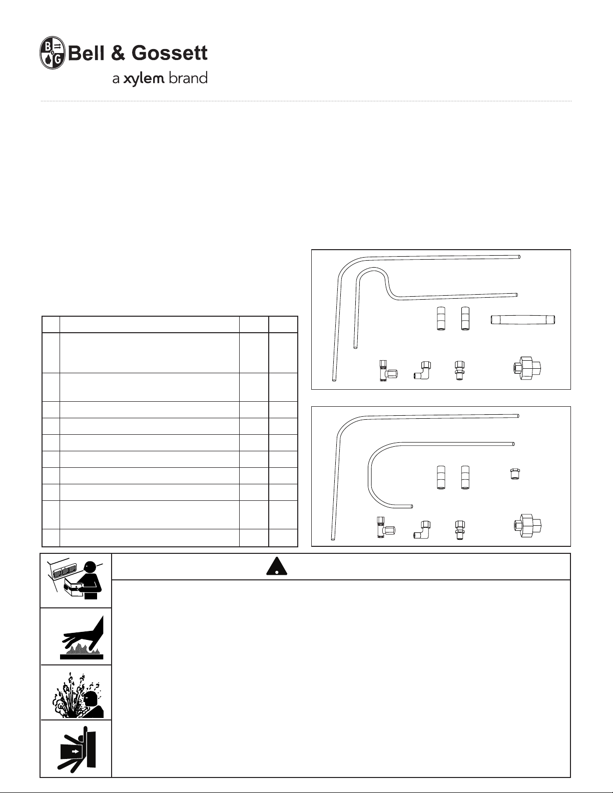
• The mounting hardware kits contain all of the hardware
required to install the pilot valve(s) on the main valve.
No. Part Description Kit A Kit B
1 L-Tubing; from main valve bottom
elbow connection to T-fitting XX
branch connection.
2 S-Tubing; from bleed orifice fitting
to T-fitting on pilot.
X
3 Nipple; 1⁄4" x 4" (8 x 101mm) X
4 Nipple; 1⁄4" x 11⁄2" (8 x 38mm) (2) XX
5 Union Connection XX
6 T-fitting XX
7 L-fitting XX
8 Bushing X
9 J-Tubing; from bleed orifice fitting
to T-fitting on pilot.
X
101⁄8" Tubing Connector XX
Kit A - For spring, air or in combination with temperature
or solenoid pilots.
Kit B - For temperature pilot or solenoid pilot only.
1
2
4
1076
1
9
4
10
76
3
5
8
5
CAUTION
WARNING
• Before using product, read and understand instructions.
• Save these instructions for future reference.
• All work must be performed by qualified personnel trained in the proper application,
installation, and maintenance of steam systems in accordance with all applicable codes
and ordinances.
• To prevent serious burns, wear heat resistant gloves when opening and closing steam
valves, or handling hot equipment.
• To prevent serious personal injury from steam pipe blow down, connect a temporary
pipe between the steam pipe opening and a drain, or stand at least 100 ft. (30m) from
the front of the pipe opening.
• To prevent property damage, personal injury, or death, cap off the gate valves if they
are not connected to a drain and when they are not in use for test or pressure relief.
Failure to follow this warning could cause property damage, personal injury or death.
WARNING
Page 2
A
B
4
3
10
7
6
8
C
D
INSTALLATION PROCEDURE
STEP 1 - Prepare Hardware and Size Tubing
TOOLS NEEDED:
Tubing cutter, adjustable or pipe wrench.
Pipe sealant should be applied to all pipe threads.
•
Do not use PTFE tape.
Note: Follow manufacturers instructions for applying
pipe sealant. Keep sealant off of the first thread.
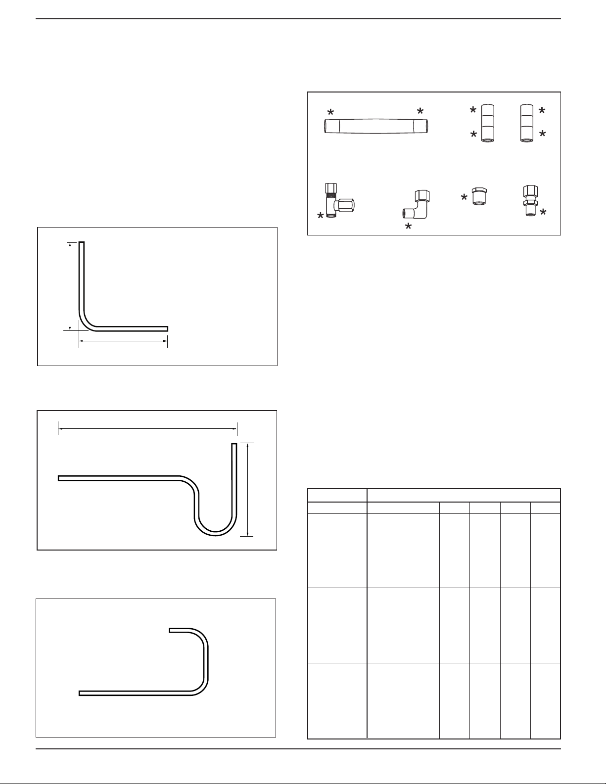
Tubing Lengths
1. L-Tube
Cut L- tube to appropriate A & B
dimensions listed on Tubing Length
chart.
pply Sealant Here
A
*
• The preformed copper tubing (included in the hardware
kits) may have to be shortened with a tubing cutter.
After cutting, ream the end to restore original tubing
diameter.
2. S-Tube
Cut S- tube to appropriate C & D
dimensions listed on Tubing
Length chart.
9. J-Tube
No cutting of J-tubes is required
Tubing Length Chart
No cutting is required if dimension is marked with an *
DIMENSIONS ( INCHES )
PILOT
Spring or air 2
Combinations 2
Temperature 2
MAIN VALVE SIZE
1
⁄2, 3⁄4, 1
1
1
⁄4 , 11⁄2
2
1
⁄2
3
4
6
1
⁄2, 3⁄4, 1
1
⁄4 , 11⁄2
1
2
1
⁄2
3
4
6
1
⁄2, 3⁄4, 1
1
⁄4 , 11⁄2
1
2
1
⁄2
3
4
6
ABCD
6
6
*811⁄16
1011⁄16
113⁄16
13
*16
6
6
*811⁄16
1011⁄16
113⁄16
13
*16
53⁄16
6
7
97⁄8
103⁄8
123⁄16
157⁄8
79⁄16
3
⁄4
81⁄16
81⁄4
91⁄8
97⁄16
105⁄16
11
⁄16
121⁄4
111⁄4
3
⁄4
113⁄4
*1115⁄16
1213⁄16
131⁄16
1315⁄16
11
⁄16
*147⁄8
715⁄16
89⁄16
7
⁄8
813⁄16
911⁄16
10
15
10
12
3
31⁄2
⁄8
6
6 3⁄8
6 3⁄8
6 3⁄8
6 3⁄8
6 3⁄8
6 3⁄8
*10
*10
*10
*10
*10
*10
*10
413⁄16
*511⁄16
515⁄16
67⁄16
715⁄16
*99⁄16
31⁄2
413⁄16
*511⁄16
515⁄16
67⁄16
715⁄16
*99⁄16
⁄16
2
Page 3

STEP 2 - Mounting Pilot Hardware
A
D
10 Pipe
Diameters
C
B
1/4 NPT
Feedback
Port
1/4 NPT Inlet
on opposite side
1/8 NPT
Signal Por t
(#6 Te e Goes
Here)
Pilot Installation Detail - For Reference Only
Applies to All Pilots
Numbers in parentheses refer to items in Kits A or B, pg. 1.
1. The pilot valve(s) can be installed on either side of the
main valve. The main valve is shipped with the Utubing and the bleed orifice installed for left-hand side
mounting of the pilot valve(s). If right-hand side
mounting of the pilot(s) is desired, the U-tubing and
the bleed orifice must be relocated to the opposite
sides of the main valve.
Note: Right-hand side and left-hand side positioning is
determined when the main valve inlet directly faces
the observer.
2. Make sure the bleed orifice is installed in the 1/8 NPT
tapping on the outlet end of the main valve on the
opposite side from the U-tubing. Remove the 1/8 NPT
pipe plug from the bleed orifice and replace it with a
1/8 NPT x 1/4" (6mm) OD tubing, straight compression
fitting (from the hardware kit #10).
3. Install the 1/4 NPT x 1-1/2" (38mm) nipple and half of
the union connection (from the hardware kit #4 and
#5) on the inlet end of the main valve.
Use the 1/4 NPT x 4" (101mm) nipple (#3) and the
4.
remaining
half of the union connection (from the hardware kit) to mount the first pilot. Mount additional
pilots as required using 1/4" steel pipe nipples.
5. Install the copper tee fitting (from the hardware kit #6)
in the 1/8 NPT signal tapping on the side of the
last pilot with the tee pointing down.
Identification of SPS Series Spring Pressure Pilot Ports
Install the L-fitting (from the hardware kit #7) in the tapping
6.
at the center of the main valve diaphragm cover.
Note: For steps 7 and 8, trim the length of the copper
tubing as required (see "Tubing Length Chart", page
2) to make a neat installation. Be sure to ream the
tube to the full tube diameter after cutting.
7. Install the S- or J-copper tubing (from the hardware
kit #2 or #9) from the tee fitting to the bleed orifice.
8. Install the L- copper tubing (from the hardware kit #1)
from the bottom of the tee fitting to the L-fitting in the
main valve diaphragm cover.
9. The 1/4" feedback tapping must be connected to the
downstream piping for either a spring or air pressure
pilot:
• Use 1/4 black steel pipe for the feedback line (B)
(not supplied with this kit).
• Install a 1/4 NPT shut off valve (D) and union (C)
in this line to allow service of the pilot while
operating the system on the by-pass line.
• The feedback line must pitch away from the pilot
to avoid erratic operation, excessive fouling and
eliminate water pockets.
When the regulator is used with a heat exchanger,
connect the feedback line (B) to the heat exchanger
shell. A tee fitting can be installed in the heat
exchanger for a vacuum breaker connection.
Identification of Air and Temperature Pilot Ports
Air Pilots
Signal
Inlet
Feedback
Signal
Inlet
Feedback
Temperature Pilot
Signal
Inlet
3
Page 4

Mounting Illustrations - For Reference Only
L-Fitting
L-Fitting
L-Fitting
L-Fitting
Feedback line connection not shown
*
Main Valve with Spring Pilot using Kit A
Main Valve with Solenoid and Pressure Pilots using Kit A
Main Valve
Bleed
Orifice
S-Tu bing
*
1/4" Union
Do Not Insulate
Below This Line
Main Valve with Temperature and Pressure Pilots using
Kit A
Main Valve
Bleed
Orifice
S-Tubing
Main Valve
Bleed
Orifice
1/4" Union
S-Tu bing
Do Not Insulate
Below This Line
Main Valve with Temperature Pilots Using Kit B
Main Valve
Bleed
Orifice
J-Tu b ing
*
1/4" Union
Do Not Insulate
Below This Line
TROUBLESHOOTING
Problem: Erratic Operation
Check: • Blockages/debris in orifice or lines
• Kinks in copper tubing
• Improper pitch in tubing/feedback line
Xylem Inc.
8200 N. Austin Avenue
Morton Grove, Illinois 60053
Phone: (847) 966-3700
Fax: (847) 965-8379
www.xyleminc.com/brands/bellgossett
Bell & Gossett is a trademark of Xylem Inc. or one of its subsidiaries.
© 2013 Xylem Inc. HS-600D February 2013 Part No. 510603
*
1/4" Union
Do Not Insulate
Below This Line
SCHEDULE:
•Inspect annually or more often. In extreme
conditions refer to main valve operation
manual for testing procedure.
 Loading...