

Page 1
INSTRUCTION MANUAL
!
HS-504
REVISION F
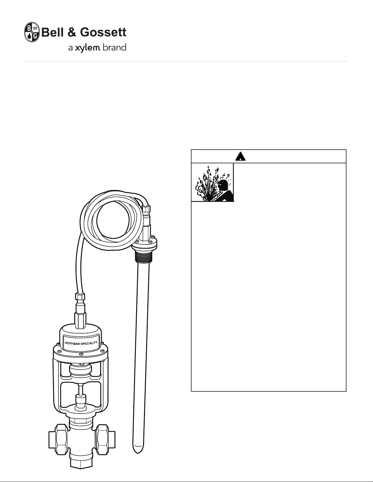
Hoffman Specialty
®
Series 1140 and 1141
Temperature Regulators
CAUTION
• FOLLOW ALL INSTALLATION AND
OPERATING INSTRUCTIONS.
• TURN OFF WATER OR STEAM
BEFORE SERVICING.
• WEAR HEAT-RESISTANT GLOVES
BEFORE MAKING ADJUSTMENTS.
• OPEN SUPPLY VALVES SLOWLY TO
PREVENT WATER HAMMER OR
SUDDEN SHOCK.
• HANDLE REGULATOR WITH
EXTREME CAUTION. DO NOT LIFT
REGULATOR BY ANY EXTERNAL
TUBING. DO NOT KINK OR TWIST
TUBING AND AVOID BENDING IT ON
A RADIUS LESS THAN 4" (100 mm).
• THE SENSING BULB MUST NOT BE
EXPOSED TO TEMPERATURES THAT
EXCEED THE RANGE LISTED ON THE
NAME PLATE.
• ALARMS OR CUT-OFFS SHOULD BE
INSTALLED ON CRITICAL
APPLICATIONS TO INDICATE
REGULATOR FAILURE. A LEAK
COULD CAUSE THE ACTUATOR TO
LOSE ITS CHARGE AND CAUSE THE
SYSTEM TO OVERHEAT.
• FAILURE TO FOLLOW THIS CAUTION
MAY RESULT IN PROPERTY DAMAGE
OR PERSONAL INJURY.
IMPORTANT: If you are uncertain as to the product’s
daptability for your application, please call the factory or
a
an authorized representative before installing or using the
product.
IMPORTANT: Do not install Series 1141 Temperature
Regulators in applications where ambient temperature
exceeds the regulator's set control temperature.
Page 2
OPERATING PRINCIPLE
C
B
A
Outlet
HOT
IN
COLD
IN
C
A
Inlet
OVER 10' (3 m)
PITCH TOWARD
STEAM REGULATOR
MAIN 1/2" PER FOOT
(
15 MM PER 0.3 m)
STEAM
MAIN
TRAP
10' (3 m) OR LESS
PITCH TOWARD STEAM REGULATOR
MAIN 1/2" PER FOOT
(15 mm per 0.3 m)
STEAM
MAIN
This Series 1140 regulator automatically controls the
flow of steam, water or other medium passing through
its valve by responding to temperature changes at the
ulb. The bulb contains a liquid which vaporizes when
b
heated. Vapor pressure generated in bulb is transmitted
through the capillary tubing to the flexible bellows which
moves the valve disc or plunger controlling the flow of
the medium through the valve. Movement of the bellows
is opposed by a spring, providing a means of adjustment. The regulator only controls within the temperature
range stamped on the name plate and can be adjusted
to control at any point within its range.
Valves used to control heating cycles are direct acting,
i.e., they shut off on increase of temperature.
Valves used to control cooling cycles are reverse acting,
i.e., they open on increase of temperature.
hree-way valves are used to mix hot and cold water,
T
or as diverting valves (see Figure 3 and 4 below).
It is necessary that the sensing bulb be completely
immersed in the fluid being controlled.
VALVE INSTALLATION
Before installing confirm proper sizing.
Oversized valves will not provide good
temperature control.
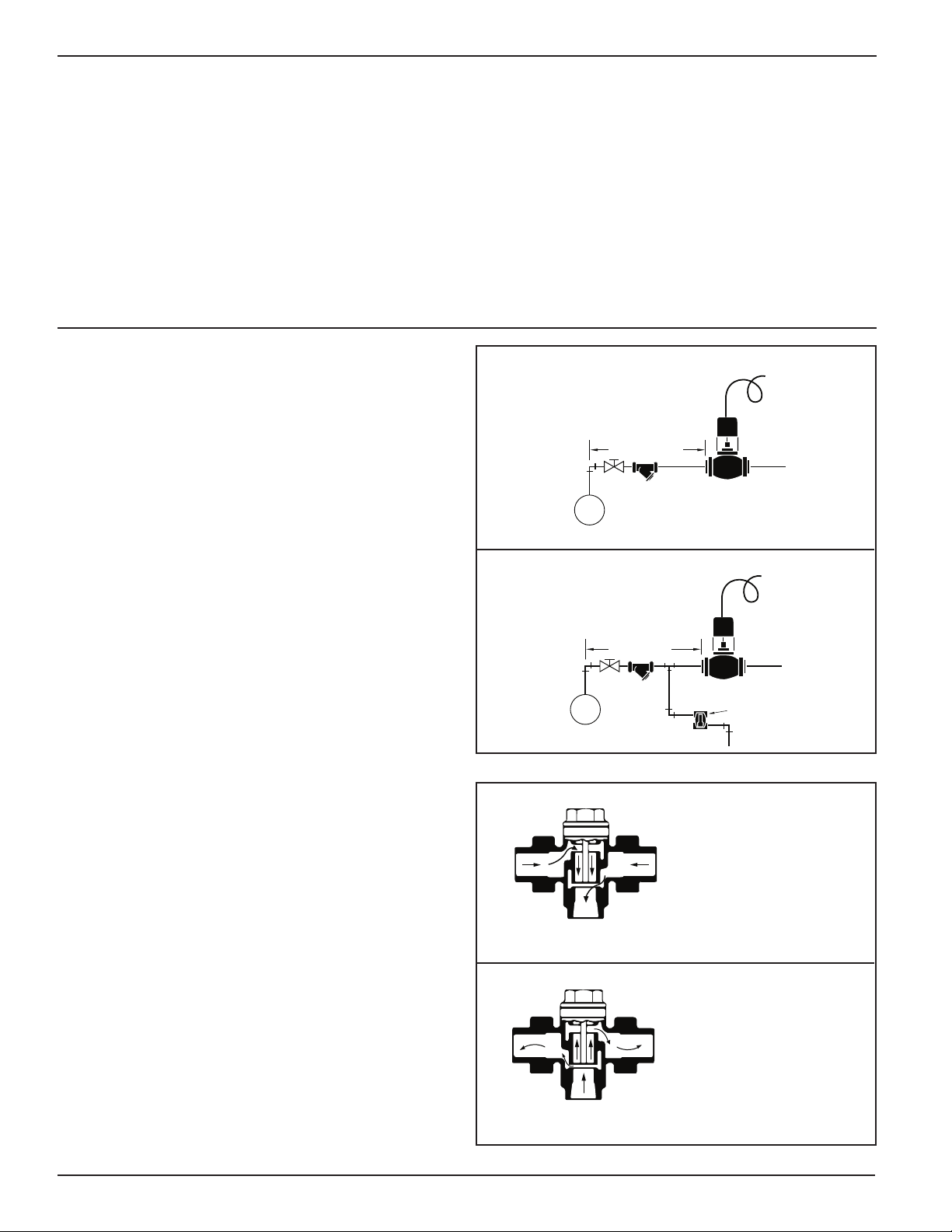
The location and installation of the regulating valve is
very important. A pipe line strainer must be installed
ahead of all double seated and balanced single seated
regulators. Single seated valves have built-in removable
strainers. However, it is still good practice to install a
strainer before all regulators and to blow all lines of
foreign matter on installation. See Figure No. 1.
The regulating valve should be installed as close as
possible to the unit being controlled. The regulator must
be installed in a vertical position, the bracket assembly
above the valve body. Install valve so that arrow cast on
valve body points in direction of steam or liquid flow.
When controlling steam, the heater or coil should be
properly vented and drained. A plain bucket trap should
not be used without some provision to eliminate air from
the coil. A drip trap should be installed ahead of all
steam regulators. See Figure No. 2.
When controlling flow of water used for cooling, the
valve can be installed on the supply end and may also
be installed on the discharge end of the unit. The
position depends largely on the particular case, as some
units, such as cylinder liners, cannot stand the full line
pressure.
When mixing hot and cold water, check valves should
be used on the supplies to the three-way valve, unless
the three way valve is used directly at heat exchanger
(see Figure No. 3) then check valve need only be on the
cold water side. To avoid temperature fluctuation of
tempered water line, the thermostatic bulb should be
located as close to three-way valve as possible.
These size valves are furnished with standard capillary
tubing, 10' (3m) length: 1/2" to 2" NPT and 2-1/2" to 4"
(65 to 100 mm).
Three-way valves are sometimes used as diverting
valves. See Figure No. 4.
2
Figure No. 1 - Trapping ahead of steam regulators
Figure No. 2 - Trapping ahead of steam regulators
Figure No. 3
Series 1140,
3-way valve
mixing service
When temperature
increases piston moves
down closing port ‘B’
opening port ‘C’.
Figure No. 4
Series 1140,
3-way valve
diverting service
When temperature
increases piston moves
down closing port ‘B’
opening port ‘C’.
Page 3
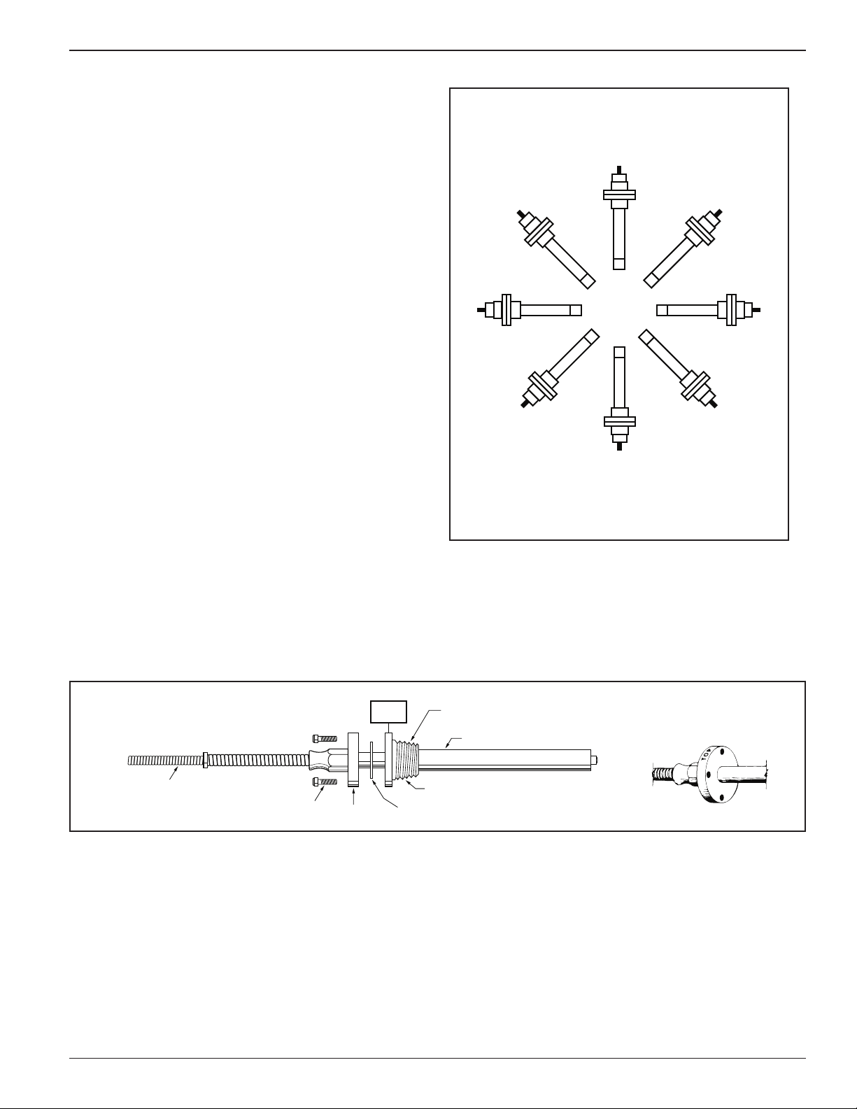
THERMOSTATIC BULB
BUSHING
GASKET
FLANGE
BUSHING SCREW
ARMORED CAPILLARY TUBING
1" NPT ON 1/2" TO 2" NPT VALVES
1-1/4" NPT ON 2-1/2" TO 4" (65 to 100 mm) VALVES
TOP
BULB INSTALLATION
IMPORTANT: Installing the bulb in the correct location
and position is extremely important.
The bulb should be installed at a point of actual system
temperature and it must be fully inserted in the fluid
being controlled.
Tanks - the bulb should be located approximately 2/3
the way up and off to a side of the tube nest. Bulbs
should be above the heating surface and no closer than
4" (100 mm) at any point.
Instantaneous heaters - the bulb should be installed in
the water outlet and as far into the heater as possible.
When a thermometer is used, it should be located PAST
the bulb at least 6 ft. (1.8 m) in the pipeline or on the
same level in the tank.
The bulb can be installed horizontally, vertically or in any
position in between the two, if the flange is uppermost
(see Figure No. 5). When installed horizontally, the word
"TOP" on the flange must be uppermost. See Figure
No. 6.
Figure No. 5 - Bulb Installation Positions
FOR CONTROLLING LIQUIDS
1. Remove the four (4) bushing screws.
2. Remove the bushing from the thermostatic bulb.
3. Determine the correct pipe size opening (see
Figure No. 6) and insert bushing in tank or
pipeline and tighten securely.
4. Insert bulb and gasket into bushing. Fasten with
the four (4) screws.
FOR CONTROLLING AIR
1. Install bulb on right angles to the air movement
and where an average temperature prevails.
Figure No. 6 - Bulb Mounting
(Incorrect)
(Incorrect)
(Incorrect)
3
Page 4
THERMOSTATIC BULB
HOT
COLD
AS CLOSE
A
S PRACTICAL
REGULATOR
T
HERMOSTATIC BULB
TOP
MIX
B
C
A
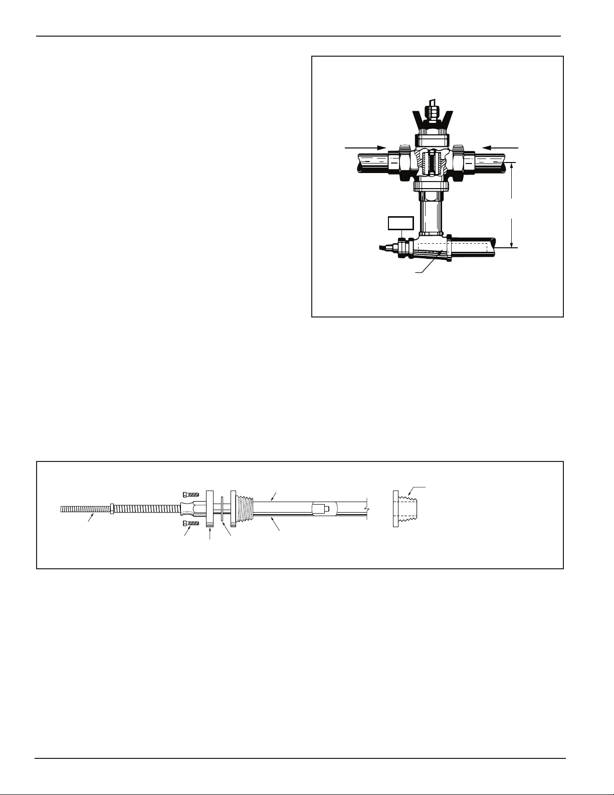
THERMOSTATIC BULB
SEPARABLE WELL
GASKET
FLANGE
BUSHING SCREW
ARMORED CAPILLARY TUBING
DISCARD BULB BUSHING WHEN
SEPARABLE WELL IS USED.
INSTALLATION
FOR THREE-WAY VALVES
1. Install the bulb as close as possible to the outlet
of the mixed water line. See Figure No. 7.
2. Immerse bulb as far as possible into the pipeline.
ALL INSTALLATIONS
The capillary tubing is the flexible tubing that connects
the bulb and the valve.
IMPORTANT: Capillary tubing may only be bent on a
4" (100 mm), or larger radius. It must never be cut,
kinked, smashed or twisted.
1. Permanently fasten the capillary tubing to a
permanent location other than steam pipes, cold
water lines, or any other place where extreme
temperatures are incurred.
2. Form a loop with a few turns of tubing and place
next to the regulator. This helps to absorb vibrations in the pipeline.
Figure No. 7 - Three-Way Valve
SEPARABLE WELL INSTALLATION
Separable wells protect the bulb and allow the bulb to be
removed without draining the pipeline or tank.
1. Install separable well in tank or piping.
2. Coat sensing bulb with high temperature grease.
3. Insert sensing bulb and gasket into the separable well.
4. Securely tighten with four (4) mounting screws.
Figure No. 8 - Separable Well Installation
4
Page 5
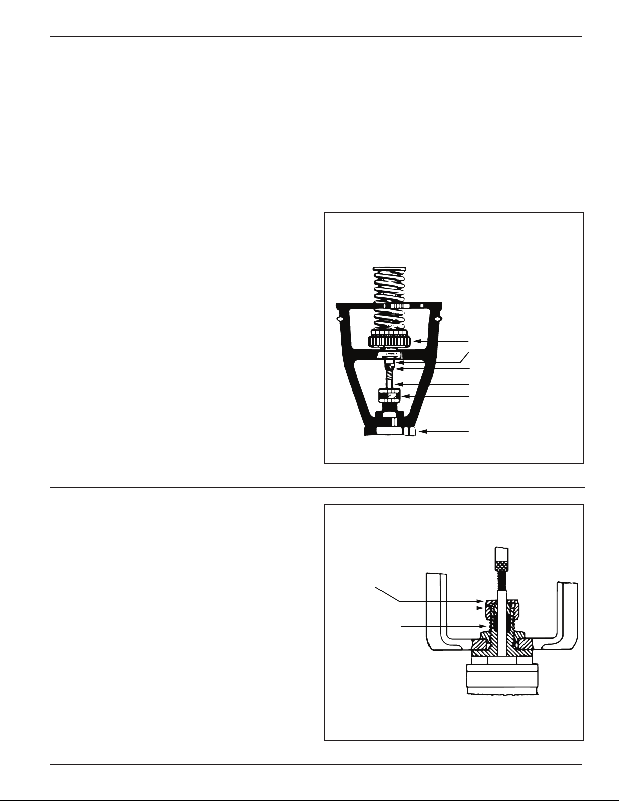
TEMPERATURE ADJUSTMENT
REGULATOR BODY
STUFFING BOX NUT
LOWER VALVE STEM
UPPER VALVE STEM
TEMPERATURE
ADJUSTMENT WHEEL
STEM ADJUSTMENT
LOCK NUT
PACKING NUT
PACKING GLAND
PACKING
This regulator can be set to control at any temperature
ithin the limits of the temperature range stamped on
w
the name plate. After placing the regulator in service,
allow about 15–30 minutes to reach stable operation,
then watch temperature, if not correct change
temperature setting as outlined hereafter. Make new
ettings as necessary until desired temperature is
s
obtained. Allow about 15–30 minutes between
changes. Oversized valves will cause extreme
temperature fluctuations.
SETTING TEMPERATURE
Turn the hand wheel in the direction indicated by arrow
(see Figure No. 9). This will compress regulating spring
and cause valve to control at a higher temperature; turning hand wheel in opposite direction causes valve to
control at a lower temperature. The wheel is mounted
on ball bearings to eliminate friction and insure easy
operation.
CHECKING VALVE STEM TRAVEL
ON TWO-WAY VALVES
The 1/2" to 2" (15 to 50 mm) bronze body regulators
have a 1/4" (6 mm) valve movement.
The 2-1/2" (65 mm) up to and including the 4" (100 mm)
flanged body valves have a 7/16" (11 mm) valve stem travel.
To check stem travel, proceed as follows:
1. See Figure No. 9.
2. Raise temperature at bulb until valve shuts off.
3. Mark lower stem using Stuffing Box Nut as
reference point.
4. Cool entire unit until bellows contracts
completely into housing.
5. Reference mark should be either 1/4" or 7/16" (6
or 11 mm) above stuffing box nut, as indicated.
If valve stem has more travel than indicated, valve will
not shut off.
CHANGING VALVE DISC MOVEMENT
Under some conditions, it may be necessary to adjust the
amount of valve movement. This may occur on oil heater
installations, where only a very small quantity of steam is
equired. Too much valve opening is usually indicated by
r
a decided fluctuation of the oil temperature.
The adjustment is made by holding the upper valve stem
nd loosening the stem adjustment lock nut and then turn-
a
ing the lower valve stem to the left (clockwise) as looking
at the arrow marks on the bracket. This will decrease the
amount of valve movement. See Figure No 8.
Always securely tighten the stem adjustment lock nut
after adjustment has been made.
Figure No. 9
MAINTENANCE
VALVE STEM PACKING:
Apply one drop of oil to the packing every three months.
Replace the packing once a year, or every 6 months
in severe environments.
STRAINERS:
Clean once a month, or more frequently if dirt or
debris is present.
Y-Strainers:
Built-in Strainers on Body code 01 or 02 (single-seated type)
TRAPS:
Follow trap manufacturer's maintenance instructions.
1. Remove packing nut.
2. Lift the packing gland.
3. Install new packing.
4. Replace and hand tighten packing nut.
1. Open the blowdown valve.
2. Allow the steam or water to flow out for 2 minutes.
3. Close the valve.
1. Remove the bottom plug.
2. Remove and wash screen
3. Reinstall screen and plug.
Figure No. 10
5
Page 6

CHANGING A THERMOSTATIC
REGULATOR BODY
STUFFING BOX NUT
LOWER VALVE STEM
UPPER VALVE STEM
TEMPERATURE ADJUSTMENT WHEEL
BELLOWS HOUSING NUT
BRACKET
UPPER VALVE STEM PLATE
BELLOWS HOUSING
BELLOWS HOUSING SCREW
ARMORED CAPILLARY TUBING
BULB BUSHING SCREWS
GASKET
BULB BUSHING
THERMOSTATIC BULB
STEM ADJUSTMENT LOCK NUT
!
!
ACTUATOR ON TWO-WAY VALVES
The Thermostatic Actuator used on the Series 1140 reg-
lators is shown in Figure No. 11. All actuator parts
u
shown form one inseparable unit, except for the bulb
bushing with its gasket and fastening screws.
he Thermostatic Actuator will only control within the
T
temperature range stamped on the name plate, which is
fastened to the bellows housing.
If it is necessary to install a new actuator, to obtain a
higher or lower range, the following procedure should be
applied. Refer to Figure No. 11.
CAUTION
ALL SUPPLY VALVES MUST BE
TURNED OFF, SYSTEM PRESSURE
MUST BE REDUCED TO 0 psi (0 bar),
AND SYSTEM TEMPERATURE MUST BE
REDUCED BELOW 100˚F (38˚C) BEFORE
REMOVING THE BULB. FAILURE TO
FOLLOW THIS CAUTION MAY RESULT
IN SERIOUS BURNS.
1. On units without a separable well, drain tank or pipe
line to a point below location of the thermostatic bulb.
2. Loosen the four (4) bulb bushing screws and slowly
break the bulb connection to make sure hot water
does not drain out, then remove four (4) screws and
take the bulb out of the bushing or well.
3. Turn temperature adjustment wheel to lowest position
(clockwise).
CAUTION
REGULATORS OPERATING LOWER THAN 120˚ - 160˚
(49˚ - 71˚C) OR IN ROOMS ABOVE 100˚F (38˚C), THE
BELLOWS MUST BE COOLED UNTIL IT CAN BE
COMPRESSED BY HAND. FAILURE TO FOLLOW
THIS CAUTION COULD DESTROY THE ACTUATOR.
4. Cool bulb and bellows at least 20˚F (-6˚C) below lowst temperature of range indicated on name plate.
e
5. Remove the bellows housing nuts and screws and lift
unit off bracket (keep bulb cool). Push down by hand
on upper valve stem plate until valve is shut. With a
pencil make a reference mark on the lower valve
stem, where stem enters stuffing box nut. This will
assist in checking total valve movement on opening
and also the thrust of the new thermostatic actuator.
6. Cool the new thermostatic actuator bulb which is to be
installed, at least 20°F (-6˚C) lower than the lowest
temperature marked on the name plate.
Actuators for valves in sizes 2-1/2" to 4" and with
ranges lower than 120° to 160°F (49 to 71°C) are
shipped with a clip, so that the bellows cannot expand
beyond limits in transit. Before removing this clip,
make sure you can compress bellows by hand. Only
then remove clip and attach housing to bracket, by
fastening the six (6) bellows housing screws. This
must be done quickly.
7. Recheck valve stem travel as outlined in paragraph
“Checking Valve Stem Travel” on page 5.
Figure No. 11
6
Page 7

CHANGING A THERMOSTATIC
REGULATOR BODY
STUFFING BOX NUT
LOWER VALVE STEM
UPPER VALVE STEM
TEMPERATURE ADJUSTMENT WHEEL
BELLOWS HOUSING NUT
BRACKET
UPPER VALVE STEM PLATE
BELLOWS HOUSING
BELLOWS HOUSING SCREW
ARMORED CAPILLARY TUBING
BULB BUSHING SCREWS
GASKET
BULB BUSHING
THERMOSTATIC BULB
STEM ADJUSTMENT LOCK NUT
!
!
ACTUATOR ON THREE-WAY VALVES
CAUTION
ALL SUPPLY VALVES MUST BE
TURNED OFF, SYSTEM PRESSURE
MUST BE REDUCED TO 0 psi (0 bar),
AND SYSTEM TEMPERATURE MUST BE
REDUCED BELOW 100˚F (38˚C) BEFORE
REMOVING THE BULB. FAILURE TO
FOLLOW THIS CAUTION MAY RESULT
IN SERIOUS BURNS.
1. Secure all water to valve and outlet from valve.
2. Drain pipe line below location of thermostatic bulb,
if no well is used.
3. When you are sure the water has been drained and all
internal pressure is relieved, remove the four bulb
bushing screws and take the thermostatic bulb out of
the bulb bushing.
4. Turn the temperature adjustment wheel to the lowest
position.
5. Cool the bulb and bellows at least 20°F (-6˚C) below the
lowest temperature range indicated on the name plate.
CAUTION
REGULATORS OPERATING LOWER THAN 120˚ - 160˚
(49˚ - 71˚C) OR IN ROOMS ABOVE 100˚F (38˚C), THE
BELLOWS MUST BE COOLED UNTIL IT CAN BE
COMPRESSED BY HAND. FAILURE TO FOLLOW
THIS CAUTION COULD DESTROY THE ACTUATOR.
6. Remove the bellows housing nuts and screws
and lift unit off bracket.
7. Turn temperature adjustment wheel up sufficiently to
ut enough tension on the spring to hold the cold port
p
shut.
8. Place a spacer 3/32" (2.4 mm) thick (2 pennies) on
upper stem plate and replace bellows housing
(completely cooled) holding it down so flange rests
on ring of bracket. If stem adjustment has not been
disturbed, stem will just move opening cold port.
Remove spacer and fasten bellows housing in place.
9. If stem does not move, unscrew upper stem from
lower stem a turn at a time until this movement is
obtained.
10. Stem should move 1/32" (0.8 mm). Screw upper
stem down on lower stem until this amount of movement is obtained.
11. Lock the two stems in this position with the stem
adjustment lock nut.
12. Attach housing to bracket.
13. Install bulb in pipe line with “top” on top.
Figure No. 12
7
Page 8

THREE WAY MIXING VALVES
CIRCULATING PUMP
CHECK
VALVE
REGULATOR
WITH 3 WAY
VALVE
COIL IN
BOILER
PORT
"A"
PORT
"C"
PORT
"B"
COLD BYPASS
HOT BYPASS
BOILER
RETURN CIRCULATION
COLD WATER
SUPPLY
TO BUILDING
IMPORTANT: When installing a three-way mixing
valve, it is necessary that return circulation be piped to
feed the cold water side of the mixing valve and heater.
See Figure No. 13.
As the temperature of the mixed liquid increases, the
piston moves toward the hot seat port B. See Figure 3
on page 2. This movement decreases the hot flow and
increases the cold flow through port C. See Figure 3 on
page 2. The thermostat maintains the piston in the
proper position for the desired mixed temperature.
Figure No. 13
TO CHECK THE OPERATION OF A THREE-WAY VALVE
USED AS A MIXING VALVE PROCEED AS FOLLOWS:
Check the packing gland to see if it is only hand tight. If
this gland is too tight, it will bind the valve stem. Then
open one or two outlets in the hot water line to establish
a flow of water through the valve. Check temperature on
thermometer. If it is not at the desired point, increase or
decrease the temperature by turning the adjustment
wheel in the proper direction for a higher or lower
temperature. The proper direction is indicated by an
arrow on valve bracket. Two turns of the adjustment
wheel should make an appreciable change in outlet
temperature.
If the temperature at the outlet drops below the desired
point, check the temperature of the hot water entering
the valve. If it is below the required temperature, the coil
or heater is not making enough hot water. This condition
must be remedied before any further adjustment can be
made on the three-way valve.
WHEN IN NEED OF INFORMATION
When contacting the factory or one of its representatives
in regard to a regulator, be sure to give all the name
plate Information, fastened to the bellows housing. This
name plate is shown in Figure No. 14.
8
Figure No. 14
Page 9

START UP PROCEDURE
!
1. Make sure inlet gate valve is closed.
2. Open outlet gate valve and all equipment drain
valves. Allow system to drain completely.
3. Make sure bypass globe valve (if provided)
is tightly closed.
4. Release any spring force on temperature
adjusting knob. Knob should be at the lowest
temperature setting for initial system startup.
5. Slightly open inlet valve (just enough to allow
steam or water into regulator). Do not allow
pressure to build up. On three-way valves open
cold water supply first, then open hot water
supply.
CAUTION: HEARING PROTECTION
IS REQUIRED IF DRAIN VALVES
ARE OPEN TO ATMOSPHERE.
Troubleshooting:
6. Allow system to stabilize.
7. Open inlet valve more.
8. Allow system to stabilize.
9. Check for leaks.
10.Close drain valves after system is hot and drain
valves are blowing steam (indication that all
condensate has been removed), or that water
valves are passing water.
11.Open inlet valve until about half open. If there are
no problems, open completely.
12.Slowly increase the spring tension by turning the
adjusting know until the desired temperature is
reached. Allow the system to stabilize (15–30
minutes). Recheck temperature setting.
Temperature Regulating
Problem:
1. System Temperature is Low.
a. Cause: Low inlet pressure.
Solution: Fully open supply valve. Clean strain-
er. Check for low boiler output or
upstream blockage and make
necessary corrections.
b. Cause: Capillary has kink. Sharp bend will
stop signal to pilot.
Solution: Replace actuator or work out kink by
hand.
c. Cause: Actuator range is incorrect. The
actuator will not operate beyond its
range.
Solution: Check indicator dial for correct
temperature range. Replace if
necessary.
d. Cause: Temperature adjustment altered.
Solution: Readjust to desired operating
condition.
e. Cause: Main valve undersized.
Solution: Check valve capacity against the
load. If insufficient, increase valve
size.
f. Cause: Piping flow restricted.
Solution: Calculate the flow velocity and
expected friction loss. If excessive,
larger inlet and outlet piping are
necessary.
Steam Valve Only
g. Cause: Condensate not draining.
Solution: Check steam trap for proper sizing
and operation. Trap should drain by
gravity into a vented return line. Avoid
lifts in the return lines.
h. Cause: Improper stem adjustment.
Solution: Check stem travel by following
instruction no. 8 on page 7.
i. Cause: Improper thermostatic bulb location.
Solution: Bulb must be fully into fluid flow being
controlled. Use reducer bushing
instead of reducers and nipples. In
storage tanks install the bulb near the
center of the tank. There must be flow
past the thermostatic bulb. As a rule
of thumb a recirculating pump should
provide a minimum of 20% design
load at all times.
j. Cause: Poor temperature response.
Solution: On units with separable well use high
temperature grate between the
thermostatic bulb and well for better
heat transfer.
k. Cause: Thermostatic bulb installed upside down.
Solution: See Figure No. 5 and follow bulb
installation instructions on page 3.
9
Page 10

Problem:
2. System Temperature High
roblem:
P
3. System Temperature Erratic
a. Cause: Bypass gate valve is open.
Solution: Close the valve.
b. Cause: Capillary has kink. Sharp bend will
stop signal to pilot.
Solution: Replace actuator or work out by
hand.
c. Cause: Actuator range incorrect. The
actuator will not operate beyond
its range.
Solution: Check name plate for correct
temperature range. Replace if
necessary.
d. Cause: Temperature adjustment altered.
Solution: Readjust to desired operating
condition.
e. Cause: Oversized valve.
Solution: Check valve capacity against the
load. If excessive, install smaller
valve. Steam valves—install a steam
pressure reducing valve to reduce
capacity.
f. Cause: Improper stem adjustment.
Solution: Check stem travel by following
instruction no. 8 on page 7.
g. Cause: Improper thermostatic bulb location.
Solution: Bulb must be fully into the flow path.
Use reducing bushing instead of
reducing coupling and nipples. In
storage tanks install the bulb near
the center of the tank. There must be
flow past the thermostatic bulb, as a
rule of thumb a recirculating pump
should provide a minimum of 20%
design load at all times.
a. Cause: Thermostatic bulb installed upside down.
Solution: The bulb mounting flange has the
word top stamped in the O.D. This
must be in the up position. The bulb
may also be installed vertically with
bulb end down, flange on top.
b. Cause: Capillary has kink or defective
actuator. Sharp bend will stop
signal to pilot.
Solution: Replace actuator or work out by
hand.
c. Cause: Thermostatic bulb installed in
poor location.
Solution: Install as close as possible to
thermometer and heater coils in
instantaneous heaters.
d. Cause: Insufficient circulation through heater.
Solution: Check circulation system, and
insure sufficient circulation.
Steam Valve Only
e. Cause: Condensate not draining.
Solution: Check steam trap for proper sizing
and operation. Trap should drain by
gravity into a vented return line. Avoid
lifts in the return lines.
f. Cause: Improper stem adjustment.
Solution: Check stem travel per instructions in
this manual.
h. Cause: Poor temperature response.
Solution: On units with separable well use
high temperature grease between
the thermostatic bulb and well for
better heat transfer.
i. Cause: Thermostatic bulb installed upside down.
Solution: See Figure No. 5 and follow bulb
installation instructions on page 3.
10
Page 11

THERMOSTATIC
BULB
RELIEF
VALVE
HOT
WATER
OUTLET
DRAIN AND
BLOW-OFF
COLD
WATER
INLET
STORAGE
HEATER
TO
TRAP
VACUUM
BREAKER
TEMPERATURE
REGULATOR
S
TEAM
INLET
"Y" STRAINER
D
RIP
TRAP
THERMOMETER
WITH
STORAGE
TANK
WITHOUT
STORAGE
TANK
COLD
WATER
INLET
CHECK VALVE
MIN.
15 INCHES
VACUUM BREAKER
"Y"
STRAINER
TEMPERATURE
REGULATOR
STEAM
TRAP
SUPPLY
VALVE
DRIP
TRAP
CIRCULATOR PUMP USED WITH
STORAGE TANK
HOT WATER OUTLET
THERMOSTATIC BULB
LOCATION WHEN USED
WITH STORAGE TANK
TEMPERATURE
REGULATOR
STEAM INLET
TO TRAP
WATER LINE
THERMOSTATIC
BULB
TYPICAL INSTALLATIONS
Figure No. 15— Controlling steam coil in storage tank
Figure No. 16 — Controlling instantaneous water heater
with or without buffer storage tank.
Figure No. 17 — Controlling steam table
11
Page 12

Figure 18 — Controlling hot water plus tempered
water at a lower temperature
Figure 20 - Controlling storage tank temperature with
a diverting valve and heat exchanger
REGULATOR WITH
3-WAY VALVE
CHECK VALVE
THERMOMETER
TEMPERED
WATER
THERMOSTATIC
BULB
CHECK VALVE
THERMOMETER
HOT WATER
THERMOSTATIC
BULB
TEMPERATURE
REGULATOR
"Y" STRAINER
HEATER
CIRCULATING PUMP
RETURN
CHECK VALVE
COLD WATER
CIRCULATOR
Figure 19 — Controlling oil cooler
TO TRAP
STEAM
INLET
DRIP
TRAP
HEAT
EXCHANGER
“B” “C”
“A”
TEMPERATURE
REGULATOR
WITH BODY
CODE 06
STORAGE TANK
THERMOSTATIC
BULB
BOILER
Figure 21 — Controlling two zone hot water job for a
restaurant
REVERSE ACTING
TEMPERATURE
REGULATOR
TO WASTE
OIL COOLER
WATER INLET
NORMALLY
CLOSED
THERMOSTATIC
BULB
WARM OIL
FROM ENGINE
Xylem Inc.
8200 N. Austin Avenue
Morton Grove, Illinois 60053
Phone: (847) 966-3700
Fax: (847) 965-8379
www.xyleminc.com/brands/bellgossett
Bell & Gossett is a trademark of Xylem Inc. or one of its subsidiaries.
© 2012 Xylem Inc. HS-504F October 2012 Part No. 517031
THERMOMETER
NOTE:
PIPING ONE SIZE
LARGER THAN THE
SYSTEM PIPING MUST
BE USED WHERE
THERMOSTATIC BULB
ENTERS LINE.
COOLED OIL
TO ENGINE
140˚F (60˚C) WATER
FOR GENERAL USE
180˚F (82˚C) WATER FOR
DISH STERILIZATION
BOILER
TEMPERATURE
REGULATOR
COLD WATER
SUPPLY
DRAIN
 Loading...