

Page 1
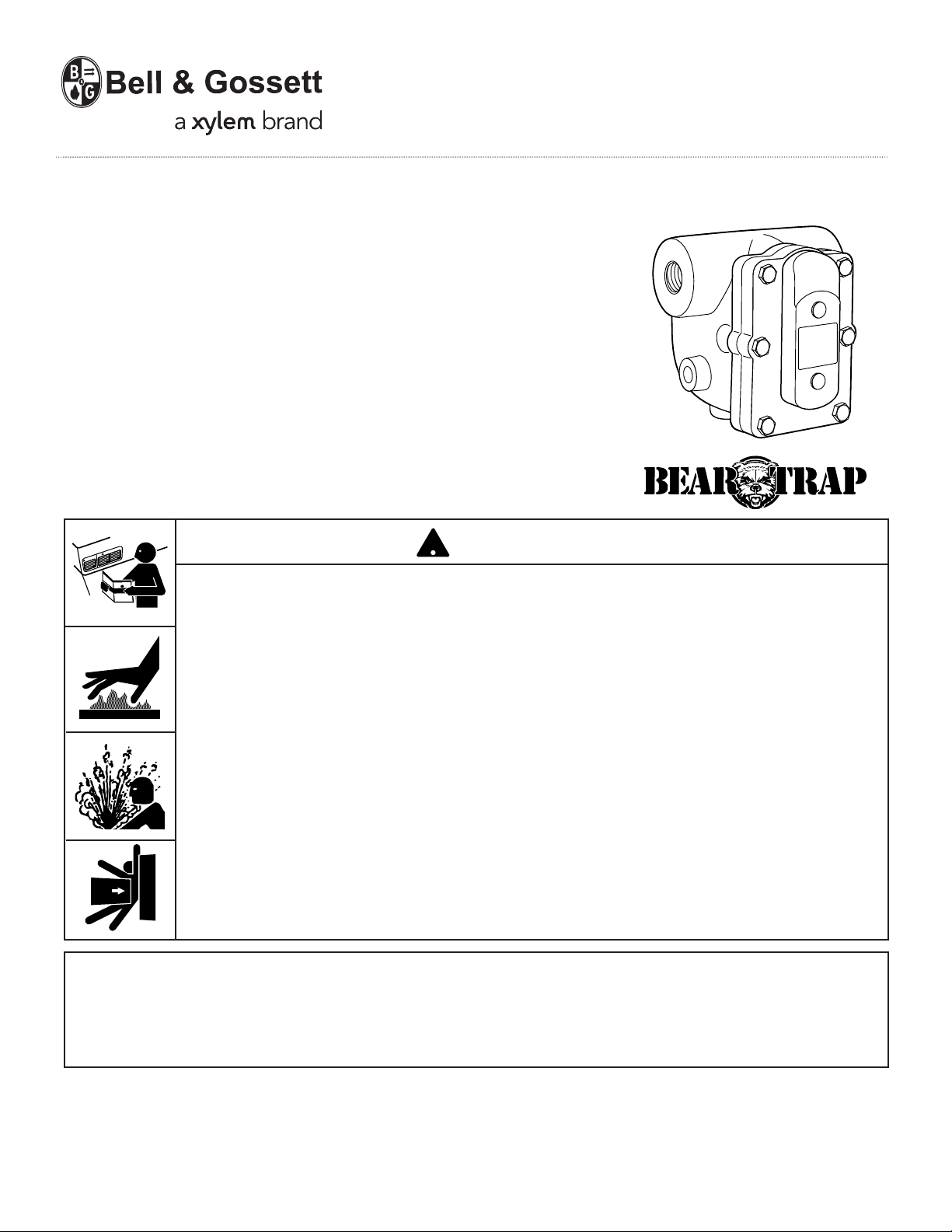
INSTRUCTION MANUAL
HS-232
REVISION C
Hoffman Specialty
®
Series I
In-line Float and Thermostatic
Steam Traps
CAUTION
WARNING
• Before using product, read and understand instructions.
• Save these instructions for future reference.
• All work must be performed by qualified personnel trained in the proper application,
installation, and maintenance of steam systems in accordance with all applicable codes
and ordinances.
WARNING
!
®
• To prevent serious burns, wear heat resistant gloves when opening and closing steam
valves, or handling hot equipment.
• To prevent serious burns, the internal pressure of the trap must be 0 psi (0 bar) before
servicing.
• To prevent serious personal injury from steam pipe blow down, connect a temporary
pipe between the steam pipe opening and a drain, or stand at least 100 ft. (30m) from
the front of the pipe opening.
• To prevent property damage, personal injury, or death, cap off the gate valves if they
are not connected to a drain and when they are not in use for test or pressure relief.
Failure to follow this warning could cause property damage, personal injury or death.
IMPORTANT: To prevent system damage from water
hammer or sudden shock, open supply valves slowly.
If you are uncertain about the product’s adaptability for
your application, please call the factory or authorized
representative before using the product.
The trap seat rating (stamped on the nameplate) must
be equal to or greater than the maximum pressure differential across the trap.
Page 2
2
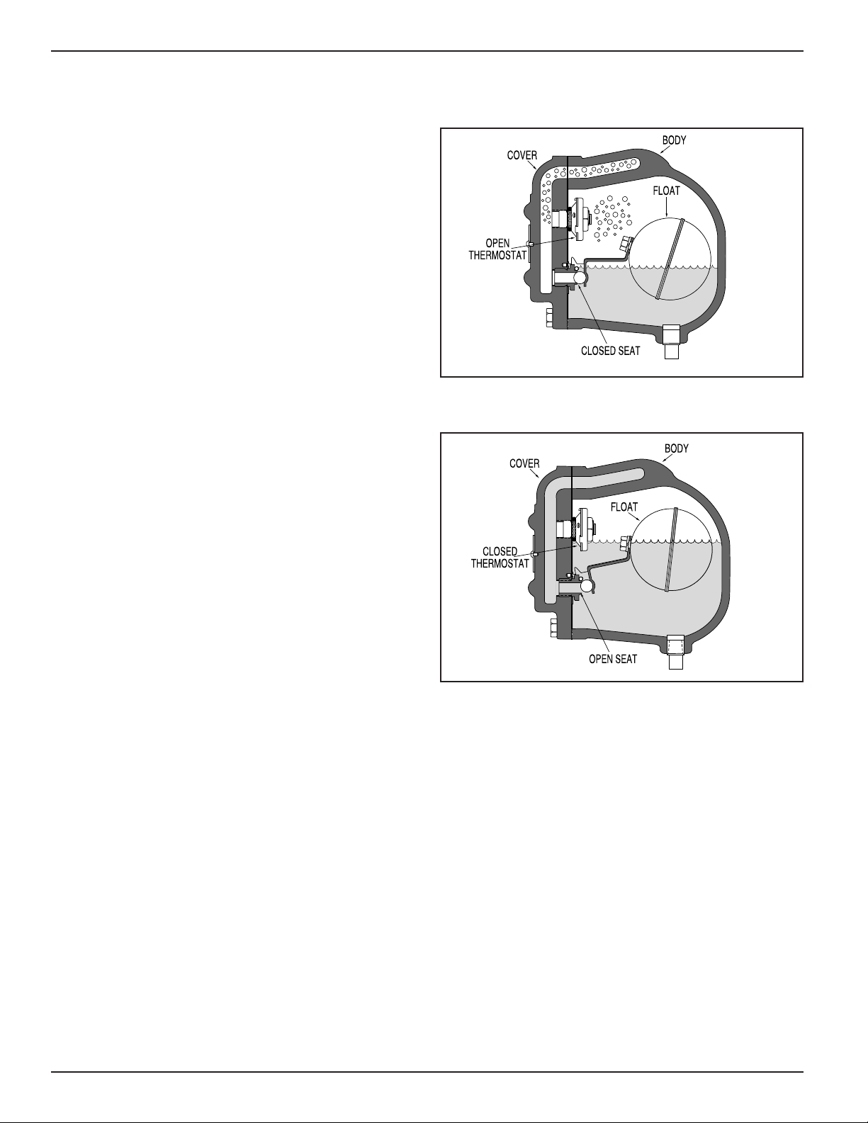
The balanced pressure thermostatic element is
open to vent air from the steam space into the
return line.
The balanced pressure thermostatic element
is closed to prevent the loss of steam into the
return line.
The float will modulate to provide continuous
drainage of condensate.
OPERATION
START-UP
NORMAL OPERATION
Page 3
3
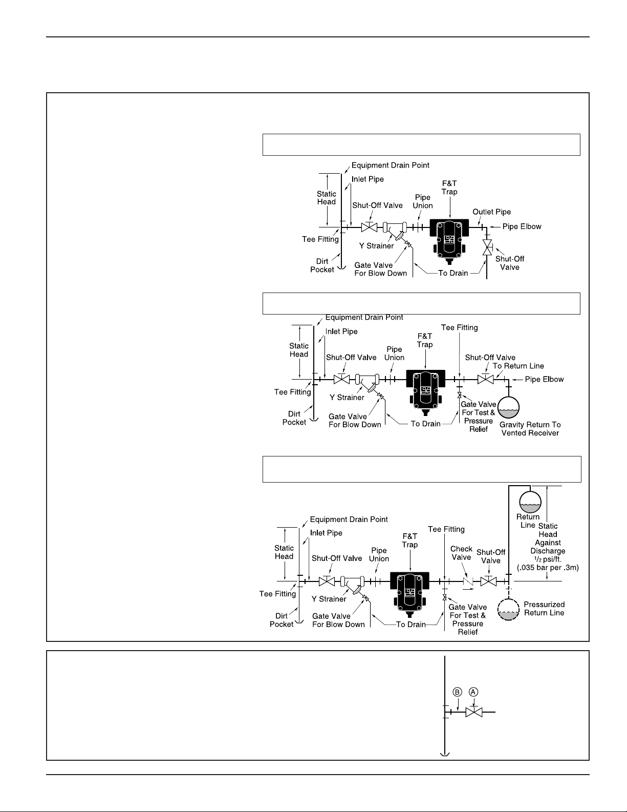
INSTALLATION –
Series I In-line Float and Thermostatic Steam Traps
TYPICAL PIPING DIAGRAMS
Trap Draining to Open Drain
Trap Draining to Gravity Return Line
Trap Draining to Overhead Return Line
or Pressurized Return Line
1. Determine where to install the trap,
based on the following requirements:
a. The trap must be located as close
as possible and below the equipment
to be drained.
b. The trap must be in a straight run
of horizontal pipe and pitched to
allow condensate to flow into the
trap inlet and away from the
trap outlet. Refer to the Typical
Piping Diagrams at the right.
c. Plenty of space around the trap is
needed for servicing, which may
include removal of the body or cover.
2. Install a shut-off valve (A) on the inlet pipe (B).
Page 4

3. Install a Y Strainer (C) on
the inlet pipe (B).
6. Close the gate valve (D). If it is not connected
to a drain, install a cap (E) on the outlet pipe (F).
Note: Remove the cap (E) when the gate valve
(D) is used for test or pressure relief. Recap when
the test or pressure relief is complete.
5a. Cap off the outlet pipe (X).
b. Slowly turn steam on with full pressure for
(5) five minutes to blowdown the inlet pipe (B).
c. Turn off steam and allow pipe to cool.
d. Remove cap from the outlet pipe (X).
To prevent serious personal injury
from steam pipe blow down, connect
a temporary pipe between the steam
pipe opening and a drain, or stand
at least 100 ft. (30m) from the front
of the pipe opening.
Failure to follow this warning
could cause property damage,
personal injury, or death.
!
WARNING
To prevent serious burns, the internal
pressure of the trap must be 0 psi (0
bar) before servicing.
Failure to follow this caution will cause
personal injury.
!
CAUTION
4. Install a gate valve for blow down (D) by con-
necting it to the Y Strainer drain tapping (C).
To prevent property damage, personal injury, or death, cap off the gate valve if it is
not connected to a drain and when it is not in use for test or pressure relief.
Failure to follow this warning could cause property damage, personal injury, or death.
!
WARNING
4
Page 5

5
7. Install a pipe union (G) on the inlet pipe (B).
G
B
8. Position the F&T trap so that the inlet pipe (B)
will connect with the “IN” tapping on the body (H),
and the “DOWN” arrow (J) is pointing down.
J
H
B
IN
9. Install the F&T trap (K) on the inlet pipe (B)
as positioned in Step 8.
K
B
10. Install a tee fitting (L) on the return line (M)
near the trap outlet (N).
N
L
M
Q
P
For Applications with a Return Line
11a. Install a gate valve (P) on the outlet pipe (Q)
for test or pressure relief.
b. Close the gate valve (P).
Page 6

12. If the gate valve (P) is not connected to a
drain, install a cap (R) on the outlet pipe (Q).
Note: Remove the cap (R) when the gate
valve (P) is used for test or pressure relief.
Recap when the test or pressure relief is
complete.
Q
P
R
13. Install a check valve (S) on the return line (M).
M
S
14. Install a shut-off valve (T) on the return line (M).
M
T
For Applications with a Gravity Return, Pressurized Return or
Return Line Above the Trap Discharge
For All Series Applications
To prevent property damage, personal injury, or death, cap off the gate valve if it is
not connected to a drain, and when it is not in use for test or pressure relief.
Failure to follow this warning could cause property damage, personal injury, or death.
!
WARNING
6
Page 7

7
15. Depending on your application, complete one
of the following steps:
a. Connect the return line (M) to a drain (U)
OR
b. Add a gravity return line (V)
OR
c. Add a pressurized return (W) or a return line
above the trap discharge (X).
M
U
V
X
W
INSTALLATION COMPLETE
MAINTENANCE
When checked regularly and properly maintained, the
Series I Float and Thermostatic Traps will provide optimum performance and long life.
SCHEDULE:
• Initially, every 2-3 days after start-up until
system is clean.
• Every 6 months thereafter.
PROCEDURE:
• To prevent serious burns, the internal pressure of the trap must be 0 psi (0 bar)
before servicing.
• To prevent serious personal injury from steam pipe blow down, connect a temporary
pipe between the steam pipe opening and a drain, or stand at least 100 ft. (30m) from
the front of the pipe opening.
Failure to follow this caution will cause personal injury.
!
CAUTION
1.Inspect joints for leaks. Stop all leaks by tightening
bolts and replacing gaskets, if necessary.
2.Clean strainers by opening the blow down valve and
allowing full steam pressure to flow out for (2) two
minutes. Then, close the valve.
3.Test traps by following the “Troubleshooting”
procedure.
Page 8

TROUBLESHOOTING
We recommend trap replacement when parts no
longer operate properly. A new trap or a complete
cover assembly is more economical than repairing or
replacing individual parts, and it will provide greater
Problem:
1. Improper Heating
a. Cause: The float assembly is not opening or
functioning properly. This could be
caused by a leak in the float.
Test: Use a thermometer to test inlet tem-
perature. A cold trap is an indication
the trap failed closed.
Solution: Disassemble the trap. Shake the float,
listening for water, and inspect for leaks.
Replace any worn or defective parts.
b. Cause: The steam pressure is higher than
the trap’s seat rating pressure which
prevents the trap from opening.
Test: Check the seat pressure rating on the
In-line F&T trap nameplate with the
available steam pressure to the
equipment being drained.
Solution: Install a new Hoffman Specialty Bear
®
Tra p
with the proper pressure range.
Note: The trap must be selected for
the maximum differential pressure that
will be encountered. A high pressure
seat may be used at lower differential
pressures, but the capacity rating will
be less than an identical size trap with
a low pressure rated seat.
reliability. If you choose to repair the trap, order
Hoffman Specialty replacement parts and follow the
Repair Procedure provided.
Problem:
2. Energy Wasted
a. Cause: A worn pin and seat, or dirt deposited
on the seat prevents tight closure.
Test: Using a stethoscope, listen for a low
pitch whistle sound. A low pitch whistle sound indicates the trap is open
and blowing live steam.
Solution: Disassemble the trap and inspect for
dirt or worn parts. Clean if dirty, or
replace if worn.
b. Cause: The thermostatic element failed open
and is blowing live steam.
Test: Using a stethoscope, listen for a low
pitch whistle sound. A low pitch whistle sound indicates the trap is open
and blowing live steam.
Solution: Disassemble the trap and replace the
thermostatic element
c. Cause: Full capacity drainage is prevented
by worn linkage.
Test: Disassemble the trap and inspect for
worn parts.
Solution: Install a new Hoffman Specialty In-
line F&T Bear Trap
®
.
Xylem Inc.
8200 N. Austin Avenue
Morton Grove, Illinois 60053
Phone: (847) 966-3700
Fax: (847) 965-8379
www.xyleminc.com/brands/bellgossett
Bell & Gossett is a trademark of Xylem Inc. or one of its subsidiaries.
© 2012 Xylem Inc. HS-232C October 2012 Part No. 510987
 Loading...