

Page 1
INSTRUCTION MANUAL
!
HS-217
REVISION d
Hoffman Specialty
®
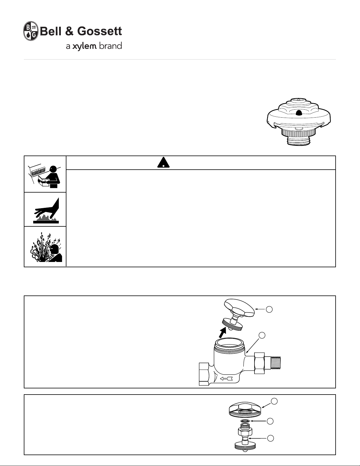
Dura-Stat® Thermostatic Module
For Spirax-Sarco Trap Model H; 1/2” (15mm) NPT
Model TB-25; 1/2” (15mm) NPT
Model TH-25; 1/2” (15mm) NPT
Model TS-25; 1/2” (15mm) NPT
N
TIO
U
CA
G
NIN
R
A
W
• Before using product, read and understand instructions.
• Save these instructions for future reference.
• All work must be performed by qualified personnel trained in the proper application,
installation, and maintenance of steam systems in accordance with all applicable codes
and ordinances.
• To prevent serious burns, wear heat resistant gloves when opening and closing
steam valves, or handling hot equipment.
CAUTION
• To prevent serious burns, the internal pressure of the trap must be 0 psi (0 bar) before
servicing.
Failure to follow this caution will cause personal injury.
INSTALLATION –
For Spirax-Sarco Trap Model H; 1/2” (15mm) NPT and Model TH; 1/2” (15mm) NPT
1. Remove the trap cover (A) from the body (B).
2a. Unscrew the thermostatic element (C) from
the cover (A).
b. Discard the old thermostatic element (C)
and washer (D).
A
B
A
D
C
Page 2
A
B
E
B
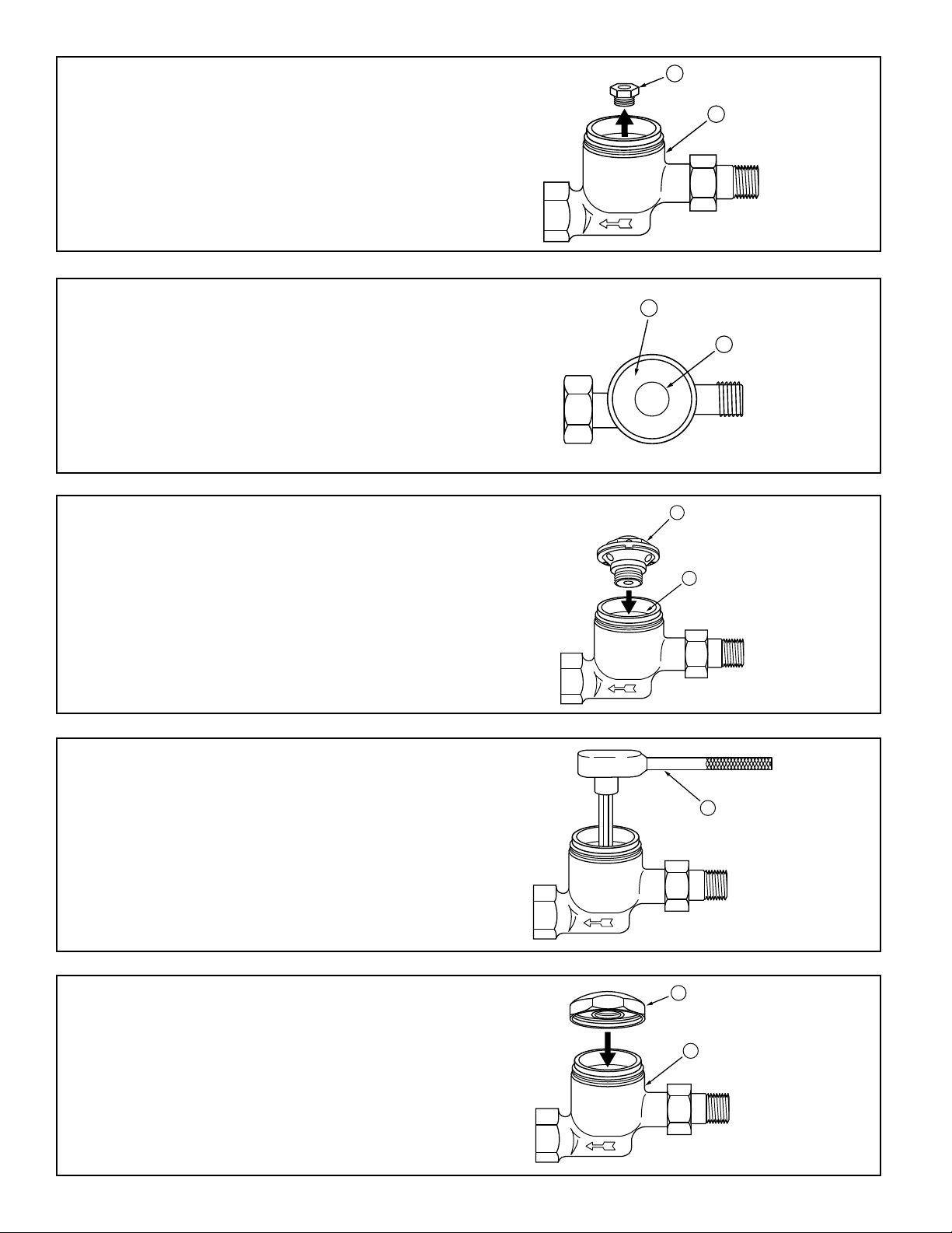
3a. Using a 5/8” (16mm) socket wrench,
G
H
remove and discard the seat (E) from
the trap body (B).
b. Discard the old seat (E).
4. Using a scraper, remove any scale or
debris inside the trap body (B) especially
around the seat area (F). Do not scratch
gasket surface area.
5. Screw the new Dura-Stat®thermostatic
module (G) into the threaded port (H)
inside the trap body.
B
F
6. Using a 3/4” (19mm) socket wrench (J),
tighten the Dura-Stat module approximately
12 lbf•ft (16 N•m).
7a. Reinstall and tighten the trap cover (A)
on the body (B).
b. Slowly open the steam supply valve.
2
J
Page 3

For Spirax-Sarco Trap Model TB-25; 1/2” (15mm) NPT
A
C
D
B
B
G
and Model TS-25; 1/2” (15mm) NPT
1. Remove the trap cover (A) from the body (B).
2a. Unscrew the coil spring (C) from
the trap cover (A).
b. Discard the coil spring (C).
3a. Remove the thermostatic element (D) from
the trap body (B).
A
B
b. Discard the old thermostatic element (D).
4a. Using a 5/8” (16mm) socket wrench,
remove the seat (E) and gasket (F) from
the trap body (B).
b. Discard the old seat (E) and gasket (F).
5. Using a scraper, remove any scale or
debris inside the trap body (B) especially
around the seat area (G). Do not scratch
gasket surface area.
E
F
B
3
Page 4

6. Screw the new Dura-Stat®thermostatic
module (H) into the threaded port (J)
inside the trap body.
7. Using a 3/4” (19mm) socket wrench (K)
tighten the Dura-Stat module to
approximately 12 lbf•ft (16 N•m).
H
J
K
8. Place the new copper spacer (L) on the
trap body (B).
9a. Reinstall and tighten the trap cover (A)
on the body (B).
b. Slowly open the steam supply valve.
MAINTENANCE
SCHEDULE:
• Replace Dura-Stat thermostatic module every 4 years.
L
B
A
B
Xylem Inc.
8200 N. Austin Avenue
Morton Grove, Illinois 60053
Phone: (847) 966-3700
Fax: (847) 965-8379
www.xyleminc.com/brands/bellgossett
Bell & Gossett is a trademark of Xylem Inc. or one of its subsidiaries.
© 2012 Xylem Inc. HS-217D October 2012 Part No. 510669
 Loading...