

Page 1
INSTRUCTION MANUAL
®
WARNING
CAUTION
!
HS-213
REVISION B
Hoffman Specialty
®
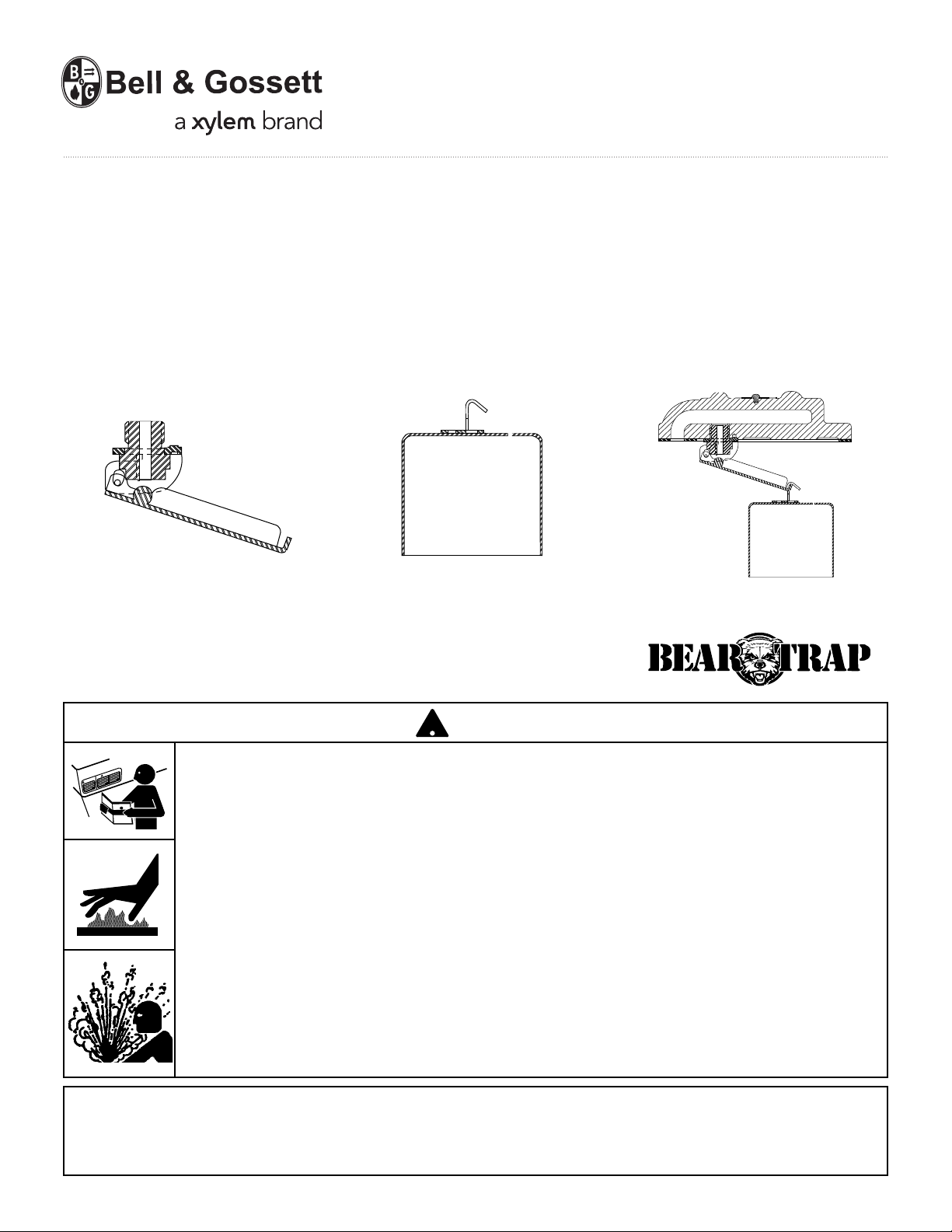
Series B1 and B2
Inverted Bucket Steam Trap
Service Parts
IP Internal Parts Kit Bucket Assembly Cover Assembly
CAUTION
• Before using product, read and understand instructions.
• Save these instructions for future reference.
• All work must be performed by qualified personnel trained in the proper application,
installation, and maintenance of steam systems in accordance with all applicable codes
and ordinances.
• To prevent serious burns, wear heat resistant gloves when opening and closing steam
valves, or handling hot equipment.
• To prevent serious burns, the internal pressure of the trap must be 0 psi (0 bar) before
servicing.
• To prevent serious personal injury from steam pipe blow down, connect a drain pipe to
the control opening to avoid exposure to steam discharge.
Failure to follow this caution will cause personal injury.
IMPORTANT: To prevent system damage from
water hammer or sudden shock, open supply
valves slowly.
The trap seat rating (stamped on the nameplate)
must be equal to or greater than the maximum
pressure differential across the trap.
Page 2
2
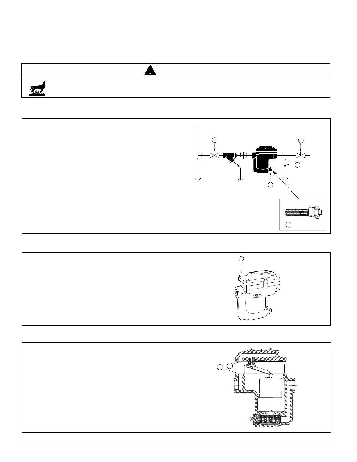
a. Close the inlet shut-off valve (A) and the outlet
shut-off valve (B) and allow the unit to cool.
• To prevent serious burns, the internal pressure of the trap must be 0 psi (0 bar) before servicing.
Failure to follow this caution will cause personal injury.
!
CAUTION
INSTALLATION PROCEDURES –
Series B1 and B2 Inverted Bucket Traps
STEP 1 - Remove Trap from Service
b. If a gate valve for test or pressure relief (C) is
installed, open it.
c. Drain condensate from the trap by removing
the drain plug (D).
OR
For models with a built-in strainer, unscrew
and remove the 3/4" (20 mm) NPT bushing
and strainer (K).
D
A
B
C
d. Remove the (6) six cover bolts (E).
E
(x6)
e. Remove the cover assembly (F) from the
body (G).
F
G
K
Page 3
3
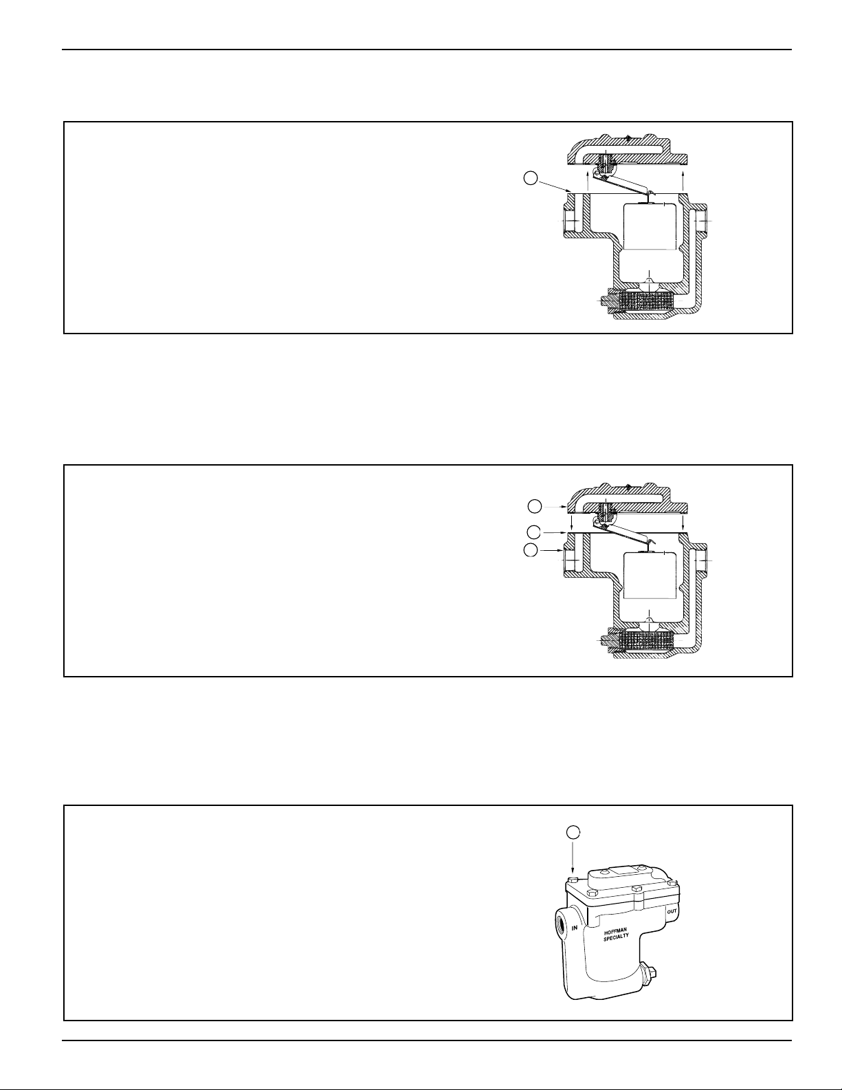
a. Carefully remove old gasket material from the
body (G). Do not scratch gasket surface area.
G
STEP 2 - Install New Service Part
If you are installing a:
COVER ASSEMBLY
b. Install a new gasket (H) on the body (G).
c. Place the new cover assembly (J) on the
gasket (H).
J
H
G
d. Reinstall the (6) six cover bolts (E) and tighten
them to a torque of 22 ft•lb (30N•m).
e. Proceed to Step 3 – Return Trap to Service.
E
(x6)
Page 4
4
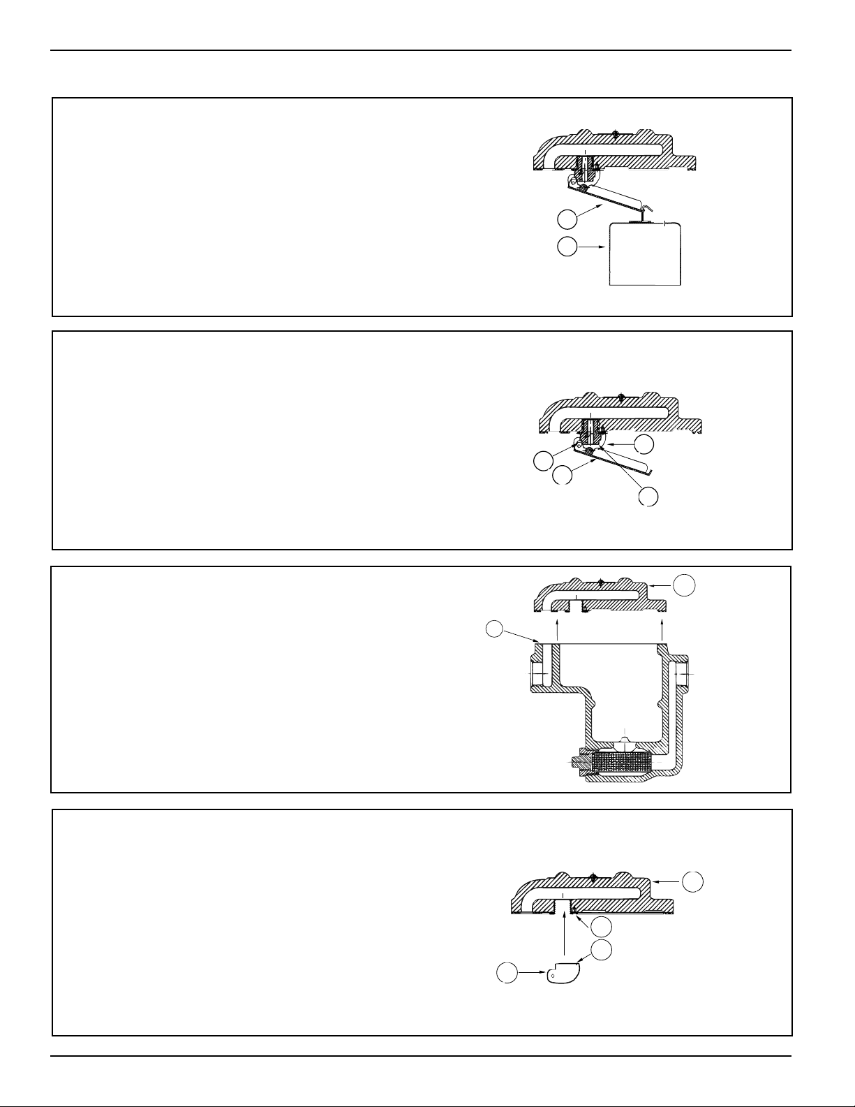
a. Unhook and remove the bucket (AA) from the
lever arm (BB).
NOTE: Save the bucket (AA).
AA
BB
If you are installing an:
INTERNAL PARTS ASSEMBLY
b. Pull pivot pin (CC) out and remove the lever
arm (DD). Unscrew the seat (FF) and remove
the seat yoke (EE).
EE
DD
CC
FF
d. Install the new seat yoke (HH) by properly
aligning the yoke dimple (JJ) with the pilot
hole (KK) in the cover (GG).
Hold the yoke in place while completing
Step e.
GG
KK
JJ
HH
c. Carefully remove old gasket material from the
body (G) and cover casting (GG). Do not
scratch surface area.
G
GG
Page 5

5
e. Carefully handle and screw the new seat (LL)
into the cover tapping (MM), protecting the
seat surface (NN) from nicks or damage.
NN
MM
LL
f. Align the new lever arm (PP) on the new seat
yoke (HH) and fasten by inserting the new pivot
pin (QQ). The lever arm ball (RR) must be
aligned with the seat (LL).
PP
QQ
LL
RR
HH
g. Hook the bucket (AA) onto the lever arm (PP).
IMPORTANT:
The open end of the bucket hook
(SS) must face away from the lever arm (PP).
AA
PP
SS
h. Install a new cover gasket (W) on the body (G).
i. Place the cover assembly (UU) on the gasket (W).
UU
W
G
Page 6

6
j. Reinstall the (6) six cover bolts (E) and tighten
the bolts to a torque of 22 ft•lb (30 N•m).
k. Proceed to Step 3 – Return Trap to Service.
E
(x6)
If you are installing a:
BUCKET ASSEMBLY
b. Install the new bucket assembly (CCC) on the
lever arm (BBB).
BBB
CCC
c. Carefully remove old gasket material from the
body (G) and cover casting (DDD). Do not
scratch gasket surface area.
DDD
G
a. Unhook and remove the bucket (AAA) from
the lever arm (BBB).
BBB
AAA
Page 7

7
d. Install a new cover gasket (EEE) on the body (G).
e. Place the cover assembly (FFF) on the gasket
(EEE).
FFF
EEE
G
f. Reinstall the (6) six cover bolts (E) and tighten
the bolts to a torque of 22 ft•lb (30 N•m).
E
(x6)
STEP 3 - Return Trap to Service
a. Insert and securely tighten the drain plug (D).
OR
For models with a built-in strainer, install a
new or clean strainer on the 3/4" (20 mm) NPT
bushing (K). Screw bushing and strainer into
the trap.
D
K
Page 8

8
d. Slowly open the shut-off valve (A) on the inlet
side of the trap.
B
e. Prime the bucket trap as follows while the
equipment is operating:
1. Close the shut-off valve (B) on the outlet
side of the trap for (1) one minute.
2. Slowly open the shut-off valve (B) on the
outlet side of the trap.
c. Open the shut-off valve (B) on the outlet side of
the trap.
b. If a gate valve (C) for test and pressure relief
is installed and it is open, close it.
C
A
B
INSTALLATION COMPLETE
a. Inspect joints for leaks. Stop all leaks by
tightening bolts (E) or replace gasket, if
necessary.
E
(x6)
INSTALLATION COMPLETE
TESTING
Page 9

9
MAINTENANCE
When checked regularly and properly maintained, the
Series B Inverted Bucket Steam Traps will provide optimum performance and long life.
SCHEDULE:
• Initially, every 2-3 days after start-up until
system is clean.
• Every 6 months thereafter.
PROCEDURE:
1.Inspect joints for leaks. Stop all leaks by tightening
bolts and replacing gaskets, if necessary.
2. Clean Y strainers by opening the blow down valve
and allowing full steam pressure to flow out for (2)
two minutes. Then, close the valve.
3. Test traps by following the “Troubleshooting”
procedure.
!
CAUTION
• To prevent serious burns, the internal pressure of the trap must be 0 psi (0 bar) before
servicing.
• To prevent serious personal injury from steam
pipe blow down, connect a drain pipe to the
control opening to avoid exposure to steam
discharge.
• To prevent hearing damage, wear ear protection
during blow down procedure.
Failure to follow this caution will cause personal
injury.
Page 10

10
TROUBLESHOOTING
We recommend trap replacement when parts no longer operate properly. A new trap is more economical than
repairing or replacing parts and it will provide greater reliability. If you choose to repair the trap, order Hoffman
Specialty replacement parts and follow the Repair Procedure provided.
Problem:
1. Improper Heating
a. Cause: The bucket bleed hole is plugged,
trapping air in the top of the bucket.
Test: Using a stethoscope, listen for a gur-
gling sound in the trap. No gurgling
indicates the condensate is not draining.
Test: If a test valve is provided, slowly open
it. The discharge should be condensate with very little steam.
Solution: Disassemble the trap and unclog the
bucket bleed hole.
b. Cause: The steam pressure is higher than
the bucket trap’s seat rating pressure
which prevents the trap from opening.
Test: Check the seat pressure rating on the
bucket trap nameplate with the available steam pressure to the equipment
being drained.
Solution: Install a new Hoffman Specialty
Inverted Bucket Bear Trap
®
with the
proper pressure range.
Note: The trap must be selected for
the maximum differential pressure that
will be encountered. A high pressure
seat may be used at lower differential
pressures, but the capacity rating will
be less than an identical size trap with
a low pressure rated seat.
c. Cause: Full capacity drainage is prevented
by worn linkage.
Test: Disassemble the trap and inspect for
worn parts.
Test: If a test valve is provided, slowly open
it. The discharge should be condensate with very little steam.
Solution: Install a new Hoffman Specialty
Inverted Bucket Bear Trap
®
.
Problem:
2. Energy Wasted
a. Cause: A worn pin and seat or dirt deposited
on the seat prevents tight closure.
Test: Using a stethoscope, listen for a low
pitch whistle sound. A low pitch whistle sound indicates the trap is open
and blowing live steam.
Test: If a test valve is provided, slowly open
it. The discharge should be condensate with very little steam.
Solution: Disassemble the trap and inspect for
dirt or worn parts. Clean if dirty or
install a new Hoffman Specialty
Inverted Bucket Bear Trap
®
if worn.
b. Cause: The trap does not close because the
linkage detached from the bucket
assembly.
Test: Using a stethoscope, listen for a low
pitch whistle. A low pitch whistle indicates the trap is open and blowing
live steam.
Solution: Disassemble the trap and inspect for
worn parts. If worn, install a new
Hoffman Specialty Inverted Bucket
Bear Trap
®
.
Page 11

11
SERVICE LOG
Date Installed ______________ Location ______________________ Identification # ___________
DATE TEST SERVICE PERFORMED SERVICED BY
OK
❑
LEAKS ❑
OK ❑
LEAKS ❑
OK ❑
LEAKS ❑
OK ❑
LEAKS ❑
OK ❑
LEAKS ❑
OK ❑
LEAKS ❑
OK ❑
LEAKS ❑
OK ❑
LEAKS ❑
OK ❑
LEAKS ❑
OK ❑
LEAKS ❑
OK ❑
LEAKS ❑
OK ❑
LEAKS ❑
OK ❑
LEAKS ❑
OK ❑
LEAKS ❑
OK ❑
LEAKS ❑
Page 12

Xylem
1) The tissue in plants that brings water upward from the roots;
2) a leading global water technology company.
We’re 12,500 people unified in a common purpose: creating innovative solutions
to meet our world’s water needs. Developing new technologies that will improve
the way water is used, conserved, and re-used in the future is central to our work.
We move, treat, analyze, and return water to the environment, and we help people
use water efficiently, in their homes, buildings, factories and farms. In more than
150 countries, we have strong, long-standing relationships with customers who
know us for our powerful combination of leading product brands and applications
expertise, backed by a legacy of innovation.
For more information on how Xylem can help you, go to www.xyleminc.com
Xylem Inc.
8200 N. Austin Avenue
Morton Grove, Illinois 60053
Phone: (847) 966-3700
Fax: (847) 965-8379
www.xyleminc.com/brands/bellgossett
Bell & Gossett is a trademark of Xylem Inc. or one of its subsidiaries.
© 2012 Xylem Inc. HS-213B October 2012 Part No. 510902
 Loading...