

Page 1

• Application
• Selection
• Installation
• Piping Diagrams
Hoffman Specialty®
Steam Traps
ENGINEERING DATA MANUAL
HS-203C
Page 2

Contents
3
Introduction
Steam Trap Functional Requirements 4
Operation, Advantages, Disadvantages
and Primary Applications 5
Chapter 1
Selection Guide Chart 10
4-Step Method for Sizing 11
Helpful Hints, Formulas and Conversion Factors 12
Properties of Saturated Steam 13
Steam Flow in Pipes 15
Condensation in Pipes 15
Chapter 2
Flash Steam Explanation and Calculation 16
Operating Pressure Limits 17
Installation and Calculating Differential Pressure 18
Drip Traps for Distribution Pipes 20
Chapter 3
Selecting Traps for Heat Exchangers 24
Lock-out Traps for Start-up Loads 27
Draining Condensate to Overhead Returns 28
Draining Submerged Coils 29
Jacketed Kettles 30
Cylinder Dryers 31
Unit Heaters 31
Steam Radiators 32
Typical Piping for Steam Heating 33
Trapping Steam Tracer Lines 39
Chapter 4
4-Step Method for Sizing Steam Lines 40
4-Step Method for Sizing Return Lines 42
Chapter 5
Testing Steam Traps 43
Chapter 6
Definition of Heating Terms 46
Page 3

Steam Trap
Functional
Requirements
Selecting the
proper type of
steam trap is an
important element
in steam systems.
There are many types of steam traps each
having its unique characteristics and system
benefits. Hoffman Specialty offers thermostatic, thermodisc, float and thermostatic, and
bucket traps which are the most commonly
used types. Deciding which type of trap to use
is sometimes confusing and, in many cases,
more than one type can be used. The following is intended to point out system conditions
that may be encountered and the characteristics of each type of trap.
Within steam systems, important considerations must be taken into account. These considerations include venting of air during
start-up; variations of system pressures and
condensing loads; operating pressure and
system load; continuous or intermittent operation of system; usage of dry or wet return
lines; and overall probability of water hammer.
Air Venting
At start-up all steam piping, coils, drums, tracer
lines, or steam spaces contain air. This air
must be vented before steam can enter.
Usually the steam trap must be capable of
venting the air during this start-up period. A
steam heating system will cycle many times
during a day. Fast venting of air is necessary
to obtain fast distribution of steam for good
heat balance. A steam line used in process
may only be shut down once a year for repair
and venting of air may not be a major concern.
Modulating Loads
When a modulating steam regulator is used,
such as on a heat exchanger, to maintain a
constant temperature over a wide range of
flow rates and varying inlet temperatures, the
condensate load and differential pressure
across the trap will change. When the condensate load varies, the steam trap must be
capable of handling a wide range of conditions at constantly changing differential pressures across the trap.
Differential Pressure Across Trap
When a trap drains into a dry gravity return
line, the pressure at the trap discharge is normally at O psig. When a trap drains into a wet
return line or if the trap must lift condensate
to an overhead return line, there will normally
be a positive pressure at the trap discharge.
To assure condensate drainage, there must
be a positive differential pressure across the
trap under all load conditions.
Water Hammer
When a trap drains high temperature condensate into a wet return, flashing may occur.
When the high temperature condensate at
saturation temperature discharges into a
lower pressure area, this flashing causes
steam pockets to occur in the piping, and
when the latent heat in the steam pocket is
released, the pocket implodes causing water
hammer. Floats and bellows can be damaged
by water hammer conditions.
When traps drain into wet return lines, a
check valve should be installed after the trap
to prevent backflow. The check valve also
reduces shock forces transmitted to the trap
due to water hammer. Where possible, wet
returns should be avoided.
Application
The design of the equipment being drained is
an important element in the selection of the
trap. Some equipment will permit the condensate to back up. When this occurs the steam
and condensate will mix and create water
hammer ahead of the trap. A shell and tube
heat exchanger has tube supports in the
shell. If condensate backs up in the heat
exchanger shell, steam flowing around the
tube supports mixes into the condensate and
causes steam pockets to occur in the condensate. When these steam pockets give up their
latent heat, they implode and water hammer
occurs, the water hammer often damages the
heat exchanger tube bundle. The trap selection for these types of conditions must completely drain condensate at saturation
temperature under all load conditions.
Steam mains should be trapped to remove all
condensate at saturation temperature. When
condensate backs up in a steam main, steam
flow through the condensate can cause water
hammer. This is most likely to occur at expansion loops and near elbows in the steam
main.
Applications such as tracer lines or vertical
unit heaters do not mix steam and condensate. In a tracer line, as the steam condenses, it flows to the end of the tracer line. Back
up of condensate ahead of the trap does not
cause water hammer. Steam does not pass
through condensate.
Vertical unit heaters normally have a steam
manifold across the top. As the steam condenses in the vertical tubes, it drains into a
bottom condensate manifold. Because steam
does not pass through the condensate, water
hammer should not occur.
4
Introduction
Page 4
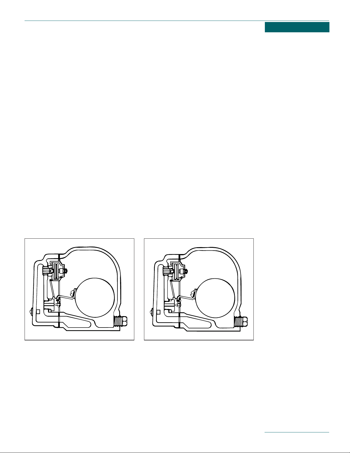
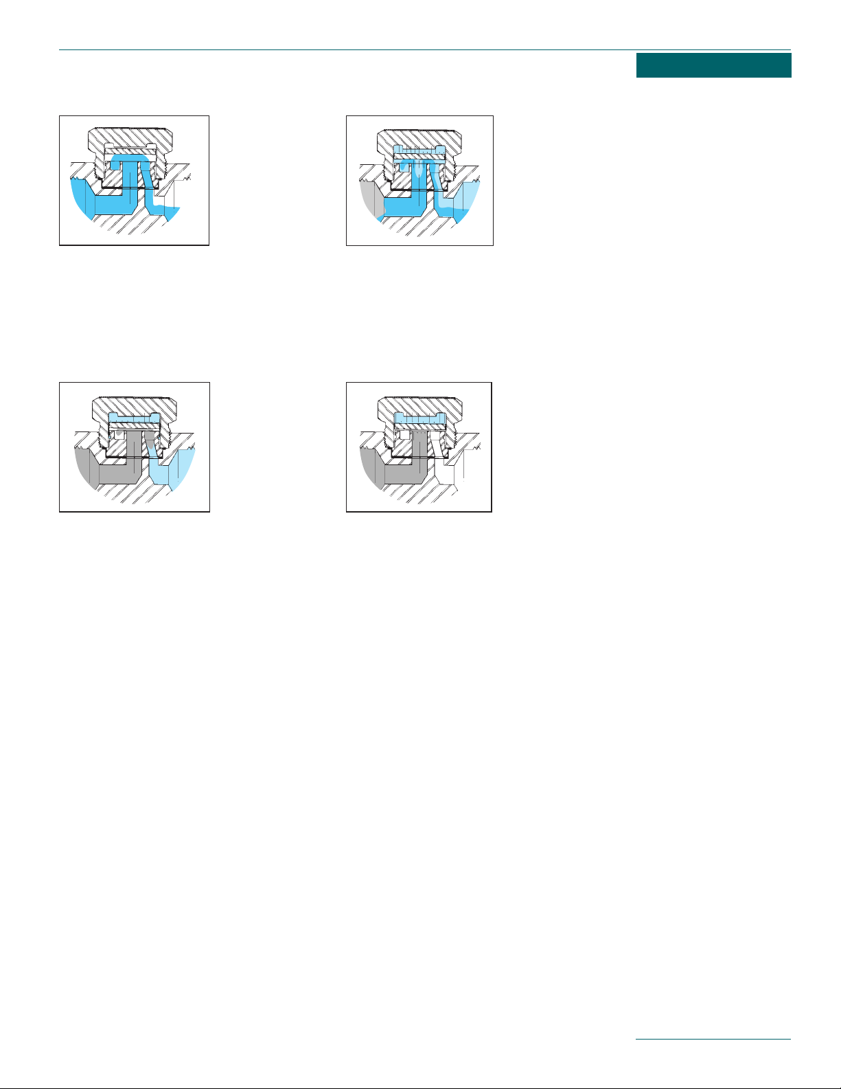
FLOAT & THERMOSTATIC TRAP
The condensate port is normally closed during
no load. As condensate enters the float chamber, the seat opens to provide drainage equal
to the condensing rate.
Primary Applications
Heating main drip traps.
Shell & tube heat exchangers.
Tank heaters with modulating temperature
regulators.
Unit heaters requiring fast venting.
Steam humidifiers.
Air blast heating coils.
Air pre-heat coils.
Modulating loads.
Fast heating start-up applications.
TRAP OPERATION
A review of the trap operating principle will
show how various types of traps meet the different system characteristics.
Float & Thermostatic Traps
Advantages
Completely drains condensate at saturation temperature.
Modulates to handle light or heavy loads,
continuous discharge equal to condensing
load.
Large ports handle high capacities.
Separate thermostatic vent allows fast
venting of air during start-up.
Modulating ports provide long life.
Cast iron bodies.
Disadvantages
Float or bellows may be damaged by water
hammer.
Primary failure mode is closed.
Does not withstand freezing temperatures.
Pressure limit of 175 psig.
FLOAT & THERMOSTATIC TRAP
During start-up the thermostatic vent is open
to allow free passage of air.
The thermostatic vent will close at near saturation temperature. The balanced design will
allow venting of noncondensables that collect
in the float chamber, when operating at
design pressure.
Operation,
Advantages,
Disadvantages,
and Primary
Applications
5
Page 5
Bucket Traps
Advantages
Completely drains condensate at saturation
temperature.
Open bucket will tolerate moderate
water hammer.
Available in pressures up to 250 psig.
Normal failure mode is open.
Cast iron bodies.
Disadvantages
Marginal air handling during start-up.
Cycles fully open or closed.
May lose prime during light loads and blow
live steam.
Requires manual priming to provide
water seal.
Does not withstand freezing temperatures.
Primary Applications
Process main drip traps.
Where condensate is lifted or drains into wet
return line.
Drum type roller dryers.
Steam separators.
Siphon type or tilting kettles.
6
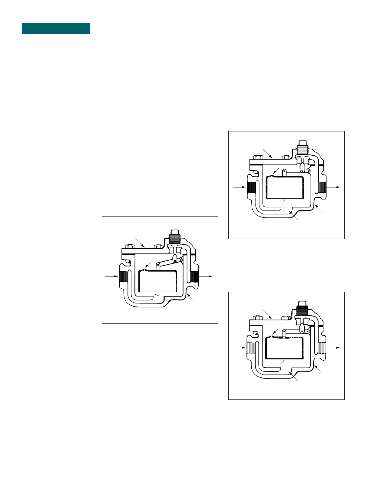
BUCKET TRAP
The trap body must be manually primed at initial start-up. Under operation the body will
remain full of condensate.
During start-up, air is vented through the
bleed hole in the top of the bucket into the
return line.
Condensate entering the trap will flow around
the bucket and drain through the open seat.
BUCKET TRAP
As steam flows into the trap it collects in the
top of the bucket. The buoyancy of the steam
raises the bucket and closes the seat.
BUCKET TRAP WITH OPTIONAL
THERMAL VENT.
An optional thermal vent installed in the bucket allows faster air venting during start-up.
COVER
A
V
INLET
BUCKET
STEAM BUBBLES
THROUGH WATER
OUTLET
BODY
COVER
A
V
INLET
BUCKET
OUTLET
BODY
COVER
A
V
INLET
BUCKET
STEAM BUBBLES
THROUGH WATER
OUTLET
BODY
Page 6
Applications
Radiators, convectors, unit heaters.
Cooking kettles.
Sterilizers.
Heating coils.
Tracer lines.
Evaporators.
NOTE: A solid fill expansion element (see
Hoffman Specialty 17K) thermostatic trap
should be used where water hammer (cavitation) may occur.
Thermostatic Bellows Type Trap
Advantages
Sub-cools condensate usually 10° to 30°F.
Normally open at start-up to provide fast
air venting.
Follows steam saturation curve to operate
over wide range of conditions.
Brass bodies.
Self draining.
Energy efficient.
Compact size and inexpensive.
Fast response to changing conditions.
Fail open models.
Disadvantages
Water hammer can damage bellows.
Superheat can damage bellows if it
exceeds trap temperature rating.
Pressure limit of 125 psig.
Cooling leg required in some applications.
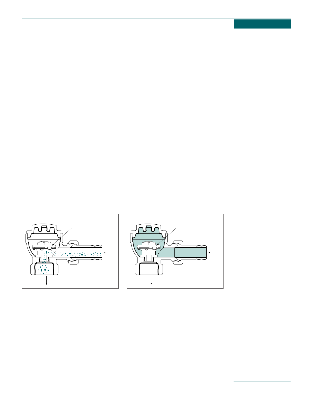
THERMOSTATIC TRAP
Thermostatic traps are normally open. This
allows fast venting of air during start-up.
THERMOSTATIC TRAP
Cold condensate during start-up drains
through the trap. As temperatures reach 10°
to 30° F of saturation, the trap closes.
During operation, thermostatic traps find an
equilibrium point to drain condensate approximately 10° to 30°F below saturation at a continuous flow.
7
INLET
OUTLET
INTERNAL
FLEXIBLE DIAPHRAGM
INLET
OUTLET
INTERNAL
FLEXIBLE DIAPHRAGM
Page 7
Disc Traps
Advantages
Completely drains condensate at saturation temperature.
May be installed vertically, to drain trap
body when steam is off, to prevent freezing.
Compact size.
Easily serviced in line, replaceable seat
and disc (some models).
All stainless steel.
Will tolerate water hammer and superheat.
Disadvantages
Noise.
Sensitive to dirt, prevents tight closing
of disc.
Available in sizes up to 1” only.
Applications
Steam tracer lines where maximum temperature is required.
Outdoor applications including drips on
steam mains.
Drying tables.
Tire mold press and vulcanizing equipment
Dry kilns.
Pressing machines.
Rugged applications (superheat & water
hammer).
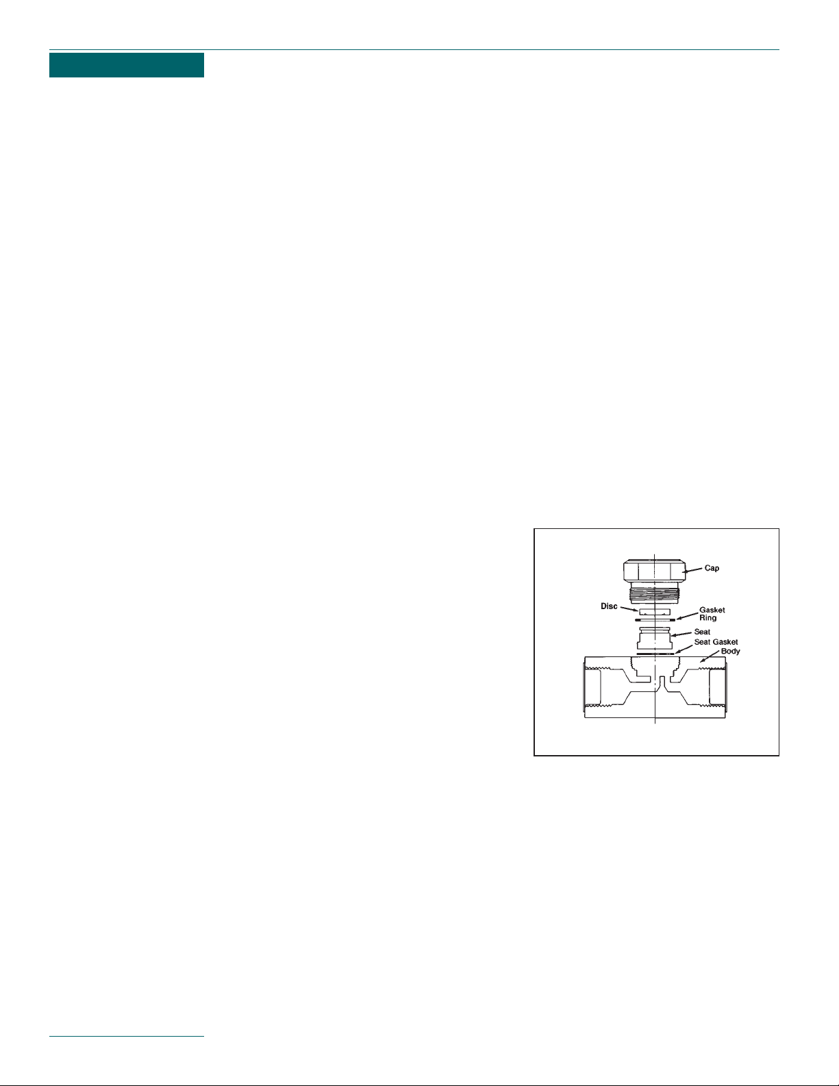
Description
Thermodisc steam traps provide dependable
performance for applications with light to
moderate condensate loads. Thermodisc
traps are excellent for high pressure drip
and steam tracing applications.
Because the disc is the only moving part,
the traps are rugged and resistant to damage. However, if the seat and disc require
servicing they may be easily replaced without removing the trap body from the piping.
8
Page 8
Orifice Traps
Advantages
No moving parts to wear.
Disadvantages
Does not close against steam.
Small hole easily plugs due to dirt.
Backs up condensate on heavy loads and
during start-up.
Does not respond to modulating loads.
Does not vent air when handling conden-
sate—causes slow system start-up and
may cause water hammer.
Not easily recognized as trap during
energy survey.
Built-in small screen plugs easily.
Discharges condensate at saturation
temperature with some live steam, often
causes excessive condensate temperatures and cavitation at condensate pumps.
Waste energy.
Sizing critical.
Applications
Should be limited to constant load
continuous operation.
Start-Up
The disc is pushed off the seat by the inlet
pressure and is held open by the impact force
of the condensate hitting the disc.
Operating
As the condensate nears saturation temperature, greater amounts of flash steam will
appear. Some of the flash steam escapes to
the area above the disc, causing the pressure
above the disc to increase, pushing the disc
closer to the seat.
Closing
When all the condensate is discharged, flash
steam enters the seat-disc chamber at high
velocity. This high velocity causes a sudden
pressure drop at the lower side of the disc
and it snaps closed against the seat.
Closed
At the instant the disc snaps closed on the
seat, the pressure above the disc is approximately equal to the upstream line pressure.
The disc is held closed because the pressurized area above the disc is much larger than
the inlet area. The pressure above the disc
decreases either by steam condensation or by
non-condensables being removed via the
micro-bleed on the disc. When the pressure is
low enough, the disc is pushed off the seat
and the process is repeated.
9
Disc Trap Operation
Page 9
Selection
Guide Chart
The proper type of steam trap selected is an
important consideration in steam systems.
There are many types of steam traps. Each
has unique characteristics and system benefits. Hoffman Specialty offers thermostatic,
float and thermostatic, bucket
and disc traps. This line chart points out system conditions that may be encountered and
suggests a trap that may best handle the
requirement. Several types of traps may be
used for a specific application. The line chart
should be used only as a guide.
10
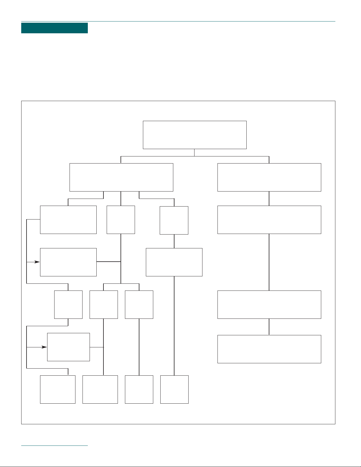
Chapter 1
Condensate must be completely
removed at saturation condition
to prevent water hammer
Type of Steam Trap Required
Based on System Conditions
Modulating load,
wide range of
condensate load
Water hammer
due to
wet returns or lifts
Float and
thermostatic
Bucket trap
with thermal
vent
Bucket
trap
Disc
trap
Constant
load
Outdoor
location
Super heat or
water hammer
Fast air
venting
required
Air vent
rate not
important
Fast air
venting
required
Condensate may be sub-cooled
ahead of trap to improve
operating efficiency of system
Varying pressure and load where fast
response is required
Pressure
up to 125 psig
Thermostatic bellows type trap
Pressure
over 175 psig
Page 10

Step 1:
Collect All Required Information.
A. Determine maximum condensate load in
Lbs./Hr. (Pounds per Hour). See “Helpful
Hints—Approximating Condensate Loads”
on page 12.
B. Inlet pressure at steam trap. It could be
different than supply pressure at boiler.
Heat exchanger applications with modulating control valves are good examples.
C. Back-pressure at steam trap. Pressure
against outlet can be due to static pressure in return line or due to lifting to
overhead return.
D. Determine Pressure Differential.
Inlet pressure (B) - Back-pressure (C)
= Differential Pressure.
Step 2:
Select Proper Type ot Trap.
A. Other Things to Consider.
1. Condensate Flow—Fluctuate?
1. Continuous?
2. Large Amount of Air?
3. Pressure—Constant? Fluctuate?
B. Application.
1. Main.
2. Drip Leg.
3. Process Heat Exchanger.
4. Other.
C. Critical Process.
1. Fail Cold.
2. Fail Hot.
Step 3:
Apply Safety Factor.
A. SFA Recommended.
1. Float & Thermostatic Trap 1.5 to 2.5.
2. Bucket Trap 2 to 4.
3. Thermostatic 2 to 4.
4. Disc Traps 1 to 1.2.
See specific applications.
B. The SFA Will Depend On Degree of
Accuracy at Step 1.
1. Estimated Flow.
2. Estimated Pressure—Inlet.
3. Estimated Pressure—Back.
Step 4:
Select Correct Trap Size.
A. Use manufacturer’s capacity table to size
trap. Capacity tables should be based on
hot condensate (some specified temperature below saturation) rather than cold
water rating. Hoffman Specialty published
actual test data, unless stated, is 10°F.
below saturation.
B. The trap seat rating must always be
higher than the maximum inlet pressure
specified.
C. When inlet to equipment is controlled by a
modulating control valve, the trap size
should be selected with a pressure rating
greater than the maximum inlet pressure
at the trap. The capacity should be
checked at the minimum differential pressure to assure complete condensate
removal under all possible conditions.
4 Step Method
for Sizing
11
Page 11

3. Steam heats a solid or slurry indirectly
through a metallic wall.
—Clothing press, cylinder driers, platen
—press.
Lbs./hr. condensate =
970 x (W
1-W2) + W1 x (T2-T1)
L x T
When:
W
1
= Initial weight of product
W
2
= Final weight of product
T
1
= Initial temp.
T
2
= Final temp.
L = Latent heat in Btu/lb.
T = Time required for drying (hours).
Note: 970 is the latent heat of vaporization
at atmospheric pressure. It is included
because the drying process requires that
all moisture in the product be evaporated.
4. Steam heats a solid through direct
contact.
—Sterilizer, autoclave
Lbs./hr. condensate =
W = Weight of material being
heated in Ibs.
S
h
= Specific heat of material
being heated.
T
1
= Initial temp.
T
2
= Final temp.
L = Latent heat Btu/lb.
T = Time to reach final temp. (hours)
Conversion Factors
One Boiler Horsepower = 140 sq. ft. EDR or
33,475 Btu/hr. or 34.5 Ibs./hr. steam at 212° F.
1,000 sq. ft. EDR yields .5 gpm condensate.
To convert sq. ft. EDR to Ibs. of condensate—
divide sq. ft. by 4.
.25 Ibs./hr. condensate = 1 sq. ft. EDR.
One sq. ft. EDR (Steam) = 240 Btu/hr. with
215°F. steam filling radiator and 70°F. air
surrounding radiator.
To convert Btu/hr. to Ibs./hr.—
divide Btu/hr. by 960.
One psi = 2.307 feet water column (cold).
One psi = 2.41 feet water column (hot).
One psi = 2.036 inches mercury.
One inch mercury = 13.6 inches water column.
Size condensate receivers for 1 min. net
storage capacity based on return rate.
Size condensate pumps at 2 to 3 times
condensate return rate.
W x S
h x (T2-T1)
L x T
Helpful Hints,
Formulas and
Conversion
Factors
Helpful Hints
Approximating Condensate Loads
Heating Water with Steam
lbs./hr. Condensate =
GPM
x Temperature Rise °F.
Heating Fuel Oil with Steam
lbs./hr. Condensate =
GPM
x Temperature Rise °F.
Heating Air with Steam Coils
lbs./hr. Condensate =
CFM
x Temperature Rise °F.
SHEMA Ratings
Thermostatic traps and F & T traps for low
pressures may be rated in accordance with
the Steam Heating Equipment Manufacturers
Association (SHEMA). SHEMA ratings have a
built-in safety factor.
Formulas
1. Steam heats a liquid indirectly through
a metallic wall.
—Cooking coils, storage tanks, jacketed
—kettles, stills.
Lbs./hr. condensate =
Q
l x 500 x Sg x Sh x (T2-T1)
L
When:
Q
l
= Quantity of liquid being
heated in gal/min
S
g
= Specific gravity
S
h
= Specific heat
L = Latent heat in Btu/lb
500 = Constant for converting
gallons per minute to
pounds per hour.
T
2
= Final temperature
T
1
= Initial temperature
2. Steam heats air or a gas indirectly
through a metallic wall.
—Plain or finned heating coils,
—unit space heaters.
Lbs./hr. condensate =
Q
g x D x Sh x (T2-T1) x 60
L
When:
Q
g
= Quantity of air or gas in ft3/min.
D = Density in Ib/ft
3
Sh= Specific heat of gas being heated.
T
1
= Initial temp.
T
2
= Final temp.
L = Latent heat in Btu/lb
60 = Minutes in hour
12
2
4
900
Page 12

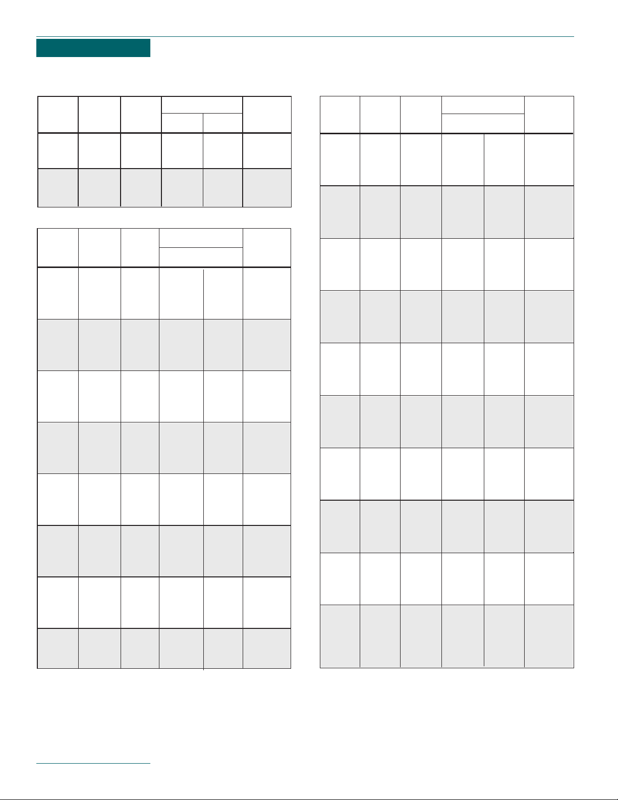
The Properties of Saturated Steam table
provides the relationship of temperature and
pressure. The table also provides Btu heat
values of steam and condensate at various
pressures and shows the specific volume of
steam at various pressures.
Saturated Steam:
Pure steam at the temperature corresponding
to the boiling point of water.
Pressure psig:
Gauge pressure expressed as Ibs./sq. in. The
pressure above that of atmosphere. It is pressure indicated on an ordinary pressure gauge.
Sensible Heat:
Heat which only increases the temperature of
objects as opposed to latent heat. In the saturation tables it is the Btu remaining in the
condensate at saturation temperature.
Latent Heat:
The amount of heat expressed in Btu required
to change 1 Ib. of water at saturation temperature into 1 Ib. of steam. This same amount
of heat must be given off to condense 1 Ib. of
steam back into 1 Ib. of water. The heat value
is different for every pressure temperature
combination shown.
Total Heat:
The sum of the sensible heat in the condensate and the latent heat. It is the total heat
above water at 32° F.
Specific Volume Cu. Ft. Per Lb.:
The volume of 1 Ib. of steam at the corresponding pressure.
See Properties of Saturated Steam table on
the following page.
Properties of
Saturated
Steam
13
Page 13
14
Properties of Saturated Steam
Specfic
Heat Content
Latent
Vacuum Saturated Volume
Btu per Ib.
Heat of
Inches of Temp Cu. ft. Saturated Saturated Vaporization
Mercury °F. per Ib. Liquid Vapor Btu per Ib.
29 79 657.0 47 1094 1047
27 115 231.9 83 1110 1027
25 134 143.0 102 1118 1017
20 161 74.8 129 1130 1001
15 179 51.2 147 1137 990
10 192 39.1 160 1142 982
5 203 31.8 171 1147 976
1 210 27.7 178 1150 971
BELOW ATMOSPHERIC PRESSURE
ABOVE ATMOSPHERIC PRESSURE (Cont.)
ABOVE ATMOSPHERIC PRESSURE
Specfic
Heat Content
Latent
Pressure Saturated Volume
Btu per Ib.
Heat of
PSI Temp Cu. ft. Saturated Saturated Vaporization
(Gauge) °F. per Ib. Liquid Vapor Btu per Ib.
0 212 26.8 180 1150 970
1 215 24.3 183 1151 967
2 218 23.0 186 1153 965
3 222 21.8 190 1154 963
4 224 20.7 193 1155 961
5 227 19.8 195 1156 959
6 230 18.9 198 1157 958
7 232 18.1 200 1158 956
8 235 17.4 203 1158 955
9 237 16.7 205 1159 953
10 239 16.1 208 1160 952
11 242 15.6 210 1161 950
12 244 15.0 212 1161 949
13 246 14.5 214 1162 947
14 248 14.0 216 1163 946
15 250 13.6 218 1164 945
16 252 13.2 220 1164 943
17 254 12.8 222 1165 942
18 255 12.5 224 1165 941
19 257 12.1 226 1166 940
20 259 11.1 227 1166 939
25 267 10.4 236 1169 933
30 274 9.4 243 1171 926
35 281 8.5 250 1173 923
40 287 7.74 256 1175 919
45 292 7.14 262 1177 914
50 298 6.62 267 1178 911
55 302 6.17 272 1179 907
60 307 5.79 277 1181 903
65 312 5.45 282 1182 900
70 316 5.14 286 1183 897
75 320 4.87 290 1184 893
80 324 4.64 294 1185 890
85 327 4.42 298 1186 888
90 331 4.24 301 1189 887
95 334 4.03 305 1190 884
100 338 3.88 308 1190 882
105 341 3.72 312 1189 877
110 343 3.62 314 1191 877
115 347 3.44 318 1191 872
120 350 3.34 321 1193 872
125 353 3.21 324 1193 867
130 355 3.12 327 1194 867
135 358 3.02 329 1194 864
140 361 2.92 332 1195 862
145 363 2.84 335 1196 860
Specfic
Heat Content
Latent
Pressure Saturated Volume
Btu per Ib.
Heat of
PSI Temp Cu. ft. Saturated Saturated Vaporization
(Gauge) °F. per Ib. Liquid Vapor Btu per Ib.
150 366 2.75 337 1196 858
155 368 2.67 340 1196 854
160 370 2.60 342 1196 854
165 373 2.53 345 1197 852
170 375 2.47 347 1197 850
175 378 2.40 350 1198 848
180 380 2.34 352 1198 846
185 382 2.29 355 1199 844
190 384 2.23 357 1199 842
195 386 2.18 359 1199 840
200 388 2.14 361 1199 838
210 392 2.05 365 1200 835
220 396 1.96 369 1200 831
230 399 1.88 373 1201 828
240 403 1.81 377 1201 824
250 406 1.75 380 1201 821
260 410 1.68 384 1201 817
270 413 1.63 387 1202 814
280 416 1.57 391 1202 811
290 419 1.52 394 1202 807
300 421 1.47 397 1202 805
325 429 1.37 405 1202 797
350 436 1.27 412 1202 790
375 442 1.19 419 1202 782
400 448 1.09 426 1202 774
425 454 1.06 432 1202 770
450 459 .972 438 1202 761
475 465 .948 444 1202 757
500 469 .873 449 1201 748
525 475 .850 455 1201 746
550 480 .820 461 1200 740
575 485 .784 466 1200 734
600 490 .733 472 1199 727
625 493 .721 476 1198 723
650 498 .692 481 1197 718
675 502 .645 485 1197 712
700 505 .642 490 1195 703
750 513 .598 498 1195 697
800 520 .555 514 1194 680
850 527 .521 523 1193 670
900 534 .489 532 1192 661
950 540 .462 540 1191 651
1000 548 .435 547 1189 642
1050 553 .413 550 1187 637
1100 558 .390 564 1185 621
1150 563 .372 572 1183 612
1200 567 .353 579 1182 603
1300 579 .322 593 1176 583
1400 588 .295 606 1172 565
1500 597 .271 619 1167 548
1570 604 .2548 624 1162 538
1670 613 .2354 636 1155 519
1770 621 .2179 648 1149 501
1870 628 .2021 660 1142 482
1970 636 .1878 672 1135 463
2170 649 .1625 695 1119 424
2370 662 .1407 718 1101 383
2570 674 .1213 743 1080 337
2770 685 .1035 770 1055 285
2970 695 .0858 801 1020 219
3170 705 .0580 872 934 62
Page 14
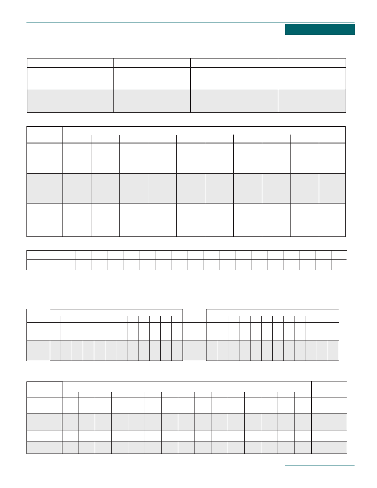
Steam Flow in Pipes
15
REASONABLE VELOCITIES for fluid flow through pipes
Pipe Size, Inches
1
⁄2
3
⁄4 111⁄4 11⁄2 221⁄2 331⁄2 441⁄2 5678910
Capacity Factor 2.0 3.5 5.5 10.0 13.5 22.5 31.5 48.5 65.0 84.0 105. 131.5 190. 255. 329. 430. 539.
COMPARATIVE CAPACITIES of different sizes of pipe
STEAM PRESSURE PSI (Gauge)
Pounds Condensed Per Hour, Per Lineal Foot of Pipe
12468102030405075100125150200
.11 .13 .14 .14 .15 .15 .16 .18 .20 .22 .26 .29 .32 .35 .40
.15 .15 .16 .16 .17 .18 .20 .23 .25 .27 .31 .35 .39 .42 .49
.21 .21 .22 .23 .23 .24 .28 .33 .36 .39 .45 .50 .55 .60 .69
.24 .25 .26 .27 .27 .29 .33 .38 .42 .46 .54 .61 .68 .74 .81
.30 .31 .32 .33 .34 .36 .41 .46 .51 .55 .65 .73 .81 .88 .97
.38 .39 .40 .41 .43 .44 .50 .56 .61 .66 .77 .86 .94 1.03 1.19
.46 .47 .48 .49 .51 .53 .61 .68 .76 .83 1.04 1.11 1.23 1.33 1.50
.55 .56 .59 .60 .62 .64 .74 .83 .91 1.00 1.24 1.32 1.46 1.59 1.81
.34 .35 .36 .37 .39 .41 .47 .53 .59 .65 .73 .81 .90 1.00 1.15
CONDENSATION RATES at 70°F. (for bare steel pipe with natural movement of air)
Pipe
Size
(Inches)
3
⁄4
1
1
1
⁄2
2
2
1
⁄2
3
4
5
Per Sq. Ft.
Heat. Surface
Sq. Ft. of
Surface =
to 1 Lineal
Ft. of Pipe
.275
.345
.497
.622
.752
.917
1.179
1.459
EXAMPLE: To get size of pipe to serve a
1
⁄2" and 3⁄4" pipe, add factors: 1⁄2" factor (2) + 3⁄4" factor (3.5) = 5.5 (1" factor).
Condensation in Pipes
Fluid Pressure PSI (Gauge) Service Velocities—FPM
SATURATED STEAM 0-15 Heating Mains 4000-6000
SATURATED STEAM 50-up Miscellaneous 6000-8000
SUPERHEATED STEAM 200-up Turbine and Boiler Leads 10000-15000
WATER 25-40 City Service 120-300
WATER 50-150 General Service 300-600
WATER 150 Boiler Feed 600
Pipe Size
PRESSURE PSI (GAUGE)
(Inches) 5 10 15 30 50 75 100 125 200 250
1
⁄2 30 40 45 60 90 120 150 180 270 330
3
⁄4 55 70 80 110 160 220 280 340 510 620
1 90 110 125 180 270 390 460 560 840 1020
11⁄4 160 200 225 325 480 650 820 990 1490 1830
11⁄2 220 270 300 450 650 900 1100 1300 2060 2550
2 370 455 520 750 1100 1500 1900 2300 3450 4200
2
1
⁄2 525 650 750 1050 1600 2175 2750 3300 4950 6050
3 800 950 1350 1600 2500 3350 4250 5150 7700 9450
31⁄2 1100 1350 1550 2200 3300 4550 5700 6900 10200 12700
4 1450 1800 2000 2900 4300 5850 7400 8900 13450 16400
5 2300 2800 3200 4600 6900 9300 11700 14100 21200 26000
6 3200 3900 4500 6400 9800 13200 16800 20300 30800 36900
8 5700 7000 8000 11400 17200 23300 29300 35400 53100 65200
10 9300 11400 13000 18900 28200 38000 48100 58100 87100 106500
12 13500 16600 18900 27000 40800 55300 69700 84200 126500 154700
SATURATED STEAM (lbs/hr) at 6000 ft/min (velocity) in iron or steel pipe
DIAMETER OF PIPE IN INCHES
3
⁄4 111⁄2 221⁄2 345681012
233445678111315
233445679111415
3344556710121417
3344557911131518
33455581012151821
34556791113162024
CONDENSATION (lbs/hr) per 100 ft. pipe with 2-in. thick 85% magnesia insulation
Pressure
PSI
(Gauge)
1
3
5
10
20
30
DIAMETER OF PIPE IN INCHES
3
⁄4 111⁄2 221⁄2 345681012
445679111316192428
4567810131518222732
5578912151820253137
5678913161922283541
66891014172124313845
67891115192428354451
Pressure
PSI
(Gauge)
50
70
100
125
150
200
Condensation in 3" and larger pipe are corrected for heat loss due to friction. Velocity taken at 8000 ft./min. Based on standard formulas.
Page 15

Flash Steam
Explanation
and
Calculation
Flash Steam
When hot condensate above the saturation
temperature under pressure, is released to
atmospheric pressure, the excess heat is
given off by reevaporation or what is commonly referred to as flash steam.
Flash steam is important because it contains
heat which can often be utilized for economy.
It is necessary to know how it is formed and
how much will be formed under given conditions.
The Btu values given in the Properties of
Saturated Steam tables provide the necessary data for calculating energy loss due to
flash steam.
Float and thermostatic traps, bucket traps,
and disc traps discharge condensate at
approximately saturation temperature.
Thermostatic traps discharge condensate 10°
to 30°F. below the saturation temperature.
Flash Steam Heat Loss Calculation
The form provided to the right will allow you to
easily calculate the flash steam loss and
associated energy cost.
Lines A, B, C, D, and E are based on the actual operating conditions. It may be necessary
to estimate the average conditions when
loads fluctuate.
Lines F, G, H and I can be filled in using the
values from the Properties of Saturated
Steam table.
The calculation for flash loss may now be
made with the annual loss determined.
The calculation of energy cost may now be
made to determine the flash loss and
required heating of make-up water to replace
the flash loss.
The amount of make-up water and water cost
can also be determined using this form.
How to Calculate Your Own Flash Steam
and Energy Loss
List Operating Conditions:
A. ____Initial Saturation Pressure.
B. ____Reduced Pressure.
C. ____System Load in Lbs. Per Hr..
D. ____Cost of Steam Per 1,000 Lbs.
E. ____Make-up Water Temperature ° F.
From Properties of Saturated Steam Table:
F. ____Btu/Lb. in Condensate at Initial
F. ____Pressure.
G. ____Btu/Lb. in Condensate at Reduced
G. ____Pressure.
H. ____Btu/Lb. Latent Heat in Steam at
H. ____Reduced Pressure.
I._____Btu/Lb. in Make-up Water.
Calculation of Flash Steam Loss
F – G
x 100 = % flash loss
______ x 100 = ______% of flash loss
C x % flash loss = lbs. per hr. loss
To obtain annual loss multiply Ibs. per hr.
Ioss x hr. per day x days per year process
operates = Ib. of flash steam annually.
Calculation of Energy Loss:
This calculation must take into consideration
that, not only are we reducing the temperature of the returns, but that the condensate
removed in the form of flash steam must be
replaced with cooler make-up water.
% of returns x system load Ibs./hr. x (F - G)
= Btu/hr. condensate cooling.
% of flash loss x system load Ibs./hr. x (F - I)
= Btu/hr. make-up water loss.
Btu condensate cooling + make-up loss
= Btu/hr. Ioss.
Btu/hr. Ioss x hr. per day x days per year
= annual Btu loss.
Btu annual loss ÷ H = equivalent Ib./yr. Ioss.
Lb./hr. Ioss ÷ 1,000 x D
= annual cost of flash steam loss.
Lb./Year Flash Loss ÷ 8.33
= Gallons per year make-up water.
16
H
Page 16

Steam Trap Operating Pressure Selection
A given size float and thermostatic trap or
bucket trap is offered with various orifice
sizes which determine the maximum pressure
rating. A Hoffman Specialty F & T trap for
example is offered with seats rated 15 psi,
30 psi, 75 psi, 125 psi and 175 psi. A low
pressure seat and pin has a larger orifice size
which provides a higher condensate rating
than a high pressure seat.
When actual operating pressure is higher than
the seat rating, the differential pressure
across the seat will prevent the trap from
opening. Thus, the trap must be selected for
the maximum differential pressure that will be
encountered. The trap capacity tables show
capacities at lower pressures to allow selection at various operating points.
A high pressure seat may be used at lower
differential pressures, however, the capacity
rating will be less than the same size trap
with a low pressure rated seat.
Operating
Pressure
Limits
17
Excessive Steam Pressure
Forces Trap Closed
ATMOSPHERIC
PRESSURE
WEIGHT OF
BUCKET
STEAM
PRESSURE
Page 17

Installation
and
Calculating
Differential
Pressure
Trap Installation
Steam traps should be installed in an accessible location at least 15 inches below the
condensate outlet of equipment or steam
mains being drained. A 15 inch static head at
the trap will provide approximately
1
⁄2 psi differ-
ential across the trap when it drains into a
vented gravity return system. During start-up,
before a positive steam pressure is achieved,
the static head is the only differential pressure across the trap. When the steam equipment is controlled by a temperature regulator,
the steam pressure will be reduced as the
valve modulates toward the closed position.
When the pressure drops to O psi, the static
head is the only differential pressure across
the trap. The differential pressure across the
trap can be increased by lowering the trap below the steam equipment.
A 2.4 ft. static head
will provide 1 psig. A greater differential pressure will reduce the size of the trap required.
Piping Details
A dirt pocket should be provided ahead of the
steam trap to collect scale and dirt. A shut-off
valve should be provided ahead of the trap to
permit service.
Strainers should be provided ahead of the
steam trap to prevent dirt from entering the
trap. Dirt entering the trap can deposit on the
seat and prevent tight closing. A blow-off valve
on the strainer will permit strainer screen
cleaning. Unions or flanges should be provided to allow removal of the trap for testing,
repair or replacement.
A test and relief valve installed after the trap
permits visual indication of the trap operation,
and assures that internal pressures are
relieved prior to servicing.
A shut-off valve in the trap outlet to the return
line isolates the trap from the return line for
service.
18
Trap Installation
Trap draining to open drain
Trap Installation
Trap draining to gravity return line
EQUIPMENT DRAIN POINT
STATIC
HEAD
SHUT-OFF VALVE
“Y”
STRAINER
DIRT
POCKET
TO DRAIN
TRAP
PRESSURE
TO RETURN LINE
TEST &
RELIEF
GRAVITY RETURN TO
VENTED RECEIVER
EQUIPMENT DRAIN POINT
STATIC
HEAD
SHUT-OFF VALVE
STRAINER
DIRT
POCKET
“Y”
TO DRAIN
TRAP
Page 18

The use of bypass piping around steam traps
is not recommended. Bypass valves, if
opened, may cause pressurization of condensate receivers and cause a safety hazard.
Where stand-by protection is desired the use
of a stand-by trap in parallel to the normal
trap is recommended.
Where the trap drains into a pressurized
return line or to an overhead return, a check
valve should be installed after the trap to prevent backflow through the trap when the
steam is off. The check valve also helps protect the trap from cavitation (water hammer)
that may occur when traps discharge high
temperature condensate into wet return lines.
Water hammer occurs when high temperature
condensate under pressure ahead of the trap
discharges into a lower pressure return line.
The high temperature condensate flashes,
causing steam pockets to form. When these
steam pockets give up their heat they implode
and cause water hammer.
Differential Pressure
The differential pressure across the trap will
be the sum of the minimum operating pressure, plus the positive static head at the trap
inlet minus any back-pressure in the return
line minus static head in the discharge piping.
Trap capacities should be calculated at the
minimum differential pressure to assure complete condensate drainage.
Lifts in the return piping should be avoided
wherever possible. High temperature condensate discharging from the trap may flash at
the lower return line pressure. The flashing
into a wet return line will cause steam pockets. As these steam pockets lose their latent
heat they implode, causing water hammer.
Water hammer can damage traps, pipe and
fittings.
Lifts in the discharge piping after a trap will
cause back-pressure. A 2.4 ft. Iift is equal to
a 1 psig pressure. This is especially important
on low pressure operation or where a modulating control valve is used to control the flow
of steam. Reduced flow will cause pressure
drops. A positive differential must be assured
under all possible conditions to assure complete condensate drainage.
19
Trap Installation
Trap draining to overhead return line or pressurized return line
Differential Pressure = P
1
minus P
2
P1(Inlet) P2(Outlet)
TRAP
EQUIPMENT DRAIN POINT
RETURN
STATIC
HEAD
SHUT-OFF
DIRT
POCKET
VALVE
“Y”
STRAINER
TO DRAIN
TRAP
CHECK
VALVE
TEST &
PRESSURE
RELIEF
SHUT-OFF
VALVE
LINE
STATIC
HEAD
AGAINST
DISCHARGE
1
/2 PSI/FT.
PRESSURIZED
RETURN LINE
Page 19

Drip Traps for
Distribution
Pipes
Drip Traps for Steam Distribution Piping
The steam distribution piping, often referred
to as steam mains, provides the link between
the boiler and the steam utilizing equipment.
The steam piping must be kept free of air and
condensate. This requirement is met with the
use of steam traps installed in the piping. The
traps used for draining the steam mains are
commonly referred to as drip traps. If the
steam mains are not adequately trapped the
results are often water hammer in the piping.
Water hammer is caused by slugs of condensate traveling at high speed in the steam
pipes, which can damage valves and piping.
Drip traps are installed in the steam mains at
all risers, ahead of all reducing valves, ahead
of all regulators, at the end of mains, throughout the piping at intervals at least every 500
feet, at expansion joints and at all steam
separators.
The size and type of drip traps used will
depend on the method used in heating the
steam mains to final pressure and temperature. The two methods commonly used are
automatic start-up and supervised start-up.
In systems using automatic start-up the
steam boiler is used to bring the mains up
to final pressure and temperature without
supervision. The drip traps must handle the
full condensing load during start-up of the
system.
In systems using supervised start-up the operator opens manual valves in the steam piping
before steam is admitted to the system.
When the system reaches normal pressure
and temperature, the manual valves are
closed. The drip traps for supervised start-up
are sized only for the running load.
The sizing of drip traps will depend on the
type of start-up used. During the initial startup of automatic startup systems, a large
amount of condensing occurs, bringing the
steam piping from ambient temperature up to
the final steam temperature.
When supervised start-up is used the drip trap
is sized only to handle the heat loss through
the steam piping.
20
Page 20

Calculation of the running load is figured
using the following formula:
Ibs./hr. running load heat loss =
L x U x ∆T x E
S x H
L = Length of steam line.
U = Heat transfer from curve in Figure 1.
T = Temperature difference between steam
temperature and minimum ambient in
degrees F.
E = 1- Efficiency of insulation (for 80% effi-
cient insulation use 1.80 = .2).
S = Linear feet of pipe to provide 1 sq. ft.
surface area.
H = Latent heat of steam in Btu/lb. (see
Properties of Saturated Steam Table).
Calculation for warm-up load at start-up:
Warm-up load Ib./hr. =
W x(T
1- T2)x.114 L
W = Weight of pipe (see table below for
weight per ft.).
T
1 = Steam temperature at saturation.
T
2 = Initial pipe temperature at ambient.
L = Latent heat of steam at final
operating pressure.
.114= Specific heat of steel or wrought
iron pipe.
21
S VALUE FT. OF PIPE PER
SQ. FT. OF SURFACE AREA
Pipe Size S Value
1" 2.904
1
1
⁄4" 2.301
1
1
⁄2" 2.010
2" 1.608
3" 1.091
4" 0.848
5" 0.686
6" 0.576
8" 0.442
10" 0.355
12" 0.299
14" 0.272
16" 0.238
18" 0.212
20" 0.191
24" 0.159
W VALUES
WEIGHT OF WELDED SEAMLESS STEEL PIPE
Schedule 40 Schedule 80
Nominal Wt. Lbs. Wt. Lbs.
Pipe Size Per Linear Ft. Per Linear Ft.
1
⁄2" .85 1.09
3
⁄4" 1.13 1.47
1" 1.68 2.17
1
1
⁄4" 2.27 3.0
1
1
⁄2" 2.72 3.63
2" 3.65 5.02
2
1
⁄2" 5.79 7.66
3" 7.58 10.25
4" 10.79 14.98
6" 18.97 28.57
8" 28.55 43.39
Page 21

Example: Assume a steam supply header to
feed tracer lines is 11/4” pipe size operating
at 30 psig and is 800 ft. Iong, insulated 75%
effect, minimum ambient at start-up is 10°F.
Calculate running load and warm-up load.
Step 1
Running load Ib./hr. =
L x U x ∆T x E
S x H
= 800 x 2.7 x (274 -10) x .25
2.301 x 926
= 66.9 Ib./hr.
Step 2
Calculate warm-up load:
C =
W x(T
1- T2) x.114
L
= (2.27 x 800) x (274 -10) x .114
926
= 59 Ibs. of steam
A warm-up time must be selected to compute
Ibs./hr. Assuming a warm-up of 15 minutes,
we must multiply 59 Ibs. x 4 = 236 Ibs./hr.
Thus, the trap must be sized for 236 Ibs./hr.
for a 15 minute start-up period, plus a safety
factor.
Step 3
We will size the trap for the large value (running load vs. warm-up load), which in almost
all instances will be the warm-up load.
Traps should be sized with a safety factor to
handle start-up and abnormal loads. Normal
practice is to size the trap at three times the
running load or two times the warm-up load.
The final sizing for our example would be to
size the trap for 236 x 2 = 472 Ibs./hr. condensate based on the differential pressure
between the header supply pressure and
return line pressure. Assuming a gravity return
line, this would be 30 psi.
Step 4
Select the trap.
Based on the previous description of traps, if
the trap from a steam header is not subject
to freezing conditions, the normal selection
would be an F & T or Bucket Trap.
If the trap is located in an area subject to
freezing, to assure complete condensate
drainage during shut-down, we should use
either a Thermostatic or Thermodisc Trap.
Based on the calculated condensate rate plus
the applied safety factor, we would go directly
to the trap manufacturer’s catalog and select
the trap.
The drip trap should be installed in a drip connection that is at least equal to the size of
the steam main for pipe size up to 4 inches.
Above 4 inch size the drip connection should
be at least 4 inches minimum or 1/2 the size
of the steam main, whichever is larger. The
height of the drip connections should be the
larger of 5 inches or 1
1
⁄2 times the diameter of
the pipe.
The static head will provide the differential
pressure across the trap during automatic
start-up until the steam pressure is above 0
psig. A 15 inch static head will provide 1/2
psi differential assuming the trap drains into a
gravity return line. A 2.4 ft. static head will
provide 1 psi differential pressure.
22
Installation at end of steam main drip trap
STATIC
HEAD
SHUT-OFF
VALVE
“Y” STRAINER
TRAP
SHUT-OFF
VALVE
Page 22

Trapping Ahead of Steam
Regulators
When steam pressure or temperature regulator valves are installed in a steam line, condensate may back up ahead of the valve
when it is off. When the valve opens with condensate backed up on the inlet side, the condensate will cause water hammer.
Where the branch connection to a control
valve is less than 10 ft., the branch line may
pitch toward the steam main to allow condensate to flow back into main.
When the branch line is over 10 ft., pitch the
branch line toward the control valve and
install a steam trap. The steam trap should
be as close to the control valve as possible.
23
Installation of drip trap ahead of riser or expansion joint
Installation of drip trap in long run of steam piping or ahead of control valves
STATIC
HEAD
SHUT-OFF
VALVE
“Y” STRAINER
TRAP
SHUT-OFF
VALVE
STATIC
HEAD
SHUT-OFF
VALVE
“Y” STRAINER
TRAP
SHUT-OFF
VALVE
10' OR LESS
PITCH TOWARD STEAM
MAIN 1/2" PER FOOT
STEAM
MAIN
OVER 10'
PITCH TOWARD
STEAM MAIN
1/2" PER FOOT
STEAM
MAIN
TRAP
Page 23

Selecting
Steam Traps
for Heat
Exchangers
Steam heating devices using a modulating
temperature regulator must operate over a
wide range of conditions. As the temperature
regulator controls the flow of steam, condesation causes a change in pressure. Thus, the
steam trap must be capable of handling a
wide range of capacities at varying pressures.
Selection of the trap for these conditions is
more involved than it would be for drip traps
or steam equipment operating at constant
pressure.
A heat exchanger is sized to heat a maximum
expected flow rate through the tubes, over the
maximum expected temperature rise with a
predetermined maximum steam operating
pressure.
When the tube side flow rate is reduced, or
the incoming fluid being heated requires less
of a temperature rise, the steam control valve
partially closes, reducing the flow of steam to
maintain a constant set temperature of the
fluid being heated. The condensing of the
steam under reduced load conditions results
in a lower steam pressure in the shell of the
heat exchanger.
During very low load conditions the condensing of the steam can create an induced vacuum in the shell of the heat exchanger. This
condition requires that a vacuum breaker be
installed to allow air to enter and relieve the
induced vacuum. Without a vacuum breaker,
the induced vacuum would cause a negative
pressure differential across the trap and the
condensate would not be drained from the
heat exchanger shell.
Complete condensate drainage under all varying pressure and condensing loads is essential to prevent tube damage due to water
hammer. The steam flow in the heat exchanger shell must pass around the tube support
sheets. If condensate builds up in the heat
exchanger shell, it will condense rapidly as
steam is mixed with it, causing water hammer. The water hammer is often evident by
indentations in the tubes and collapsed
tubes.
Thus, it becomes evident that the design condensing rate at design pressure is not the
only load the trap must handle. The condensing load of a heat exchanger designed for 15
psi may in fact be in excess of 90% at 0 psig.
When the heat exchanger is selected, a fouling factor is added to assure adequate tube
area as scale builds up on the tube walls.
Before this scale develops, the heat exchanger is in fact oversized which results in a lower
steam operating pressure.
A steam trap must then be selected to handle
the full condensing load with the heat
exchanger operating at 0 psig. The heat
exchanger may operate at a slight vacuum
due to the condensing of steam. A vacuum
breaker is required on a heat exchanger to
prevent induced vacuum. The differential
required to open the vacuum breaker is usually less than 0.25 psi.
Recommended practice is to install the trap
as far below the heat exchanger as possible.
The minimum distance should be 15 inches.
A 15 inch static head will develop approximately 0.5 psig at the trap inlet, less the differential required to open the vacuum
breaker. Assuming 0.25 psi to open the vacuum breaker, a properly sized trap must be
capable of draining the full rated condensing
load with 0.25 psi differential across the trap,
draining into an atmospheric gravity return
line. A static head of 2.4 feet will provide 1
psig. The differential required to open the vacuum breaker must be subtracted from the
static pressure to determine the differential
across the trap.
Selecting the type of trap becomes the next
step. Traps that operate in response to temperature should be avoided for heat exchanger operation. This eliminates thermostatic
traps from our selection. As described above,
the trap must be capable of responding to
varying condensing rates at various differential pressures. The two types of traps that can
meet these requirements are Float and
Thermostatic Traps and Bucket Traps. The
Float and Thermostatic Trap has the ability to
24
Chapter 3
Steam to Fluid Heat Exchanger
HEATED FLUID
OUT
FLUID TO BE
HEATED IN
VACUUM BREAKER
HEAT EXCHANGER
SHELL
TEMPERATURE
REGULATOR
STEAM LINE
TUBE SUPPORTS
HEAT EXCHANGER
TUBE BUNDLE
F&T TRAP
Page 24

modulate over a wide range of conditions, providing a drainage rate equal to the system
load. The Float and Thermostatic Trap also
has a separate thermostatic vent to provide
quick passage of air during start-up or during
a change of condition. The bucket trap will
completely drain the condensate but operates
in cycles between full open and close. The
bucket trap has a slower air venting rate
unless fitted with a separate thermostatic element. Return line sizing can be minimized
using the Float and Thermostatic Trap due to
its modulating feature which provides a continual flow equal to the condensing rate.
General practice in sizing traps is to allow a
safety factor in the selection. During start-up
when the heat exchanger shell is cold, the
steam piping is cold and the fluid to be heated may be at less than design temperature.
All these conditions will cause a higher steam
condensing rate. Float and Thermostatic Trap
safety factors are normally 1.5 to 2.5 times
rated load. Bucket Trap safety factors are normally 2 to 4 times rated load .
Guidelines for selecting traps for heat
exchangers using modulating steam temperature regulators are as follows:
—Select capacity based on maximum condensing load at minimum differential pressure
that can occur. The heat exchanger manufacturer can provide this information.
—No lifts should be installed in the return line
piping. The trap must drain into an atmospheric gravity return line.
—Install a vacuum breaker to prevent induced
vacuum in the heat exchanger from causing a
reverse in differential pressure across the
trap.
—Install the trap as far below the heat
exchanger as possible to develop a static
pressure to the trap inlet. The minimum
should be 15 inches.
—Select a trap that provides complete
drainage of condensate. Avoid use of temperature controlled traps.
—Allow an adequate safety factor for start-up
conditions.
25
Typical Heat Exchanger Installation
Float & Thermostatic Traps assure complete condensate drainage
at saturation temperature. They also modulate to handle varying
condensate loads associated with temperature regulators. The
thermostatic element provides rapid air venting during start-up.
PRESSURE
GAUGE
Y STRAINER
FLOAT AND
THERMOSTATIC
GATE
VALVE
CONDENSATE
RETURN
TRAP
THERMOSTATIC
FLOAT AND
TRAP
Y STRAINER
Y STRAINER
GATE
VALVE
BREAKER
VACUUM
GATE
VALVE
GLOBE
VALVE
TEMPERATURE
REGULATING VALVE
HEAT EXCHANGER
15" MINUMUM
RECOMMENDED
GATE
VALVE
PRESSURE
GAUGE
CONNECTION TO
HEAT EXCHANGER
HOT
WATER
THERMOMETER
COLD
WATER
CONDENSATE
RETURN
Page 25

Condensate Coolers
When heat exchangers are selected for operation above 2 psig, consideration should be
given to the addition of a condensate cooler.
The justification will vary depending on the
size of the heat exchanger and the actual
time the unit is in operation.
With a condensate cooler, the discharge from
the trap on the primary heat exchanger is
piped through a water-to-water heat exchanger.
This lowers the condensate temperature and
recovers wasted heat. A second trap is then
installed on the discharge of the condensate
cooler to maintain saturation pressure and
prevent flashing and water hammer in the
condensate cooler.
The water-to-water heat exchanger design differs from steam heat exchangers. The waterto-water heat exchanger has internal baffles
to direct the water flow across the tubes to
improve heat transfer. The water-to-water heat
exchangers are externally distinguishable
because the top and bottom shell openings
are both the same size. The steam-to-water
heat exchangers have a large opening in the
top for the steam inlet and a smaller bottom
outlet for the condensate drainage.
When a modulating steam regulator is used
on the steam-to-water heat exchanger, the
vacuum breaker will allow air to enter to prevent an induced vacuum from holding up condensate. The F & T Trap must be installed 15
inches below the heat exchanger to provide
condensate drainage when the internal pressure drops to O psig. A separate Thermostatic
Trap should be provided to allow the air to be
vented when the pressure increases above O
psig. This trap bypasses the condensate cooler to allow free passage of the air into the
gravity return line.
The fluid in the condensate cooler on the tube
side, may be the same fluid that is to be heated in the steam heat exchanger when the initial temperature is sufficiently low. When the
initial temperature of the fluid is too high to
cool the condensate below 212°F, other fluids
may be heated. Heating domestic hot water
or pre-heating boiler make-up water are two
possibilities.
26
Piping Detail of Condensate Cooler
When fluid being heated is too hot to cool condensate below 212°F., other heating
requirements may be circulated through the condensate cooler.
TEMPERATURE
REGULATOR
STEAM LINE
HEAT EXCHANGER
THERMOSTATIC
TRAP
F&T TRAP
HEAT EXCHANGER
CONDENSATE COOLER
TO RETURN
LINE
Page 26

Lock-out Traps For Draining Condensate
Under Low Pressure.
In the discussion of trap operation, we pointed out that if the differential pressure across
the trap seat exceeds the trap pressure rating, the trap will fail closed. This occurs when
the differential force across the seat and pin
exceeds the drop-away force created by the
weight of the float or bucket and linkage.
Under certain conditions we can use a trap
with a low differential pressure in a high pressure application to drain condensate during
start-up or operation at reduced pressure.
Low pressure F & T or Bucket Traps may be
used for lock-out applications.
Lock-out Trap Used to Drain
Underground Steam Main.
One application of a lock-out trap is to drain
condensate from underground steam lines
during start-up. The low pressure trap connected to an open drain or sump drains condensate during start-up. When the steam line
pressure exceeds the trap rating it will close
and remain closed. The differential pressure
will then allow the condensate to flow through
the high pressure drip trap and be recovered
through the return line.
This method may also be used where a modulating temperature regulator may reduce pressure ahead of the trap. When the regulator
reduces the flow of steam, the pressure in
the steam space drops due to the condensing
rate in relation to steam flow. The low pressure trap connected to a sump or drain will
then operate when the pressure drops approximately to the rated pressure of the trap.
Lock-Out
Traps for
Start-Up
Loads
27
Lock-out trap used to drain underground steam main
POWER
PLANT
UNDERGROUND WET
RETURN LINE
UNDERGROUND
STEAM LINE
LOCKOUT
TRAP TO DRAIN
HIGH PRESSURE
DRIP TRAP
Page 27

Draining
Condensate to
Overhead
Returns
Draining Condensate to Overhead
Returns or into Pressurized Return Lines
When a positive pressure is assured across
the steam trap, 1 psi will raise condensate
2 feet. When a positive pressure is not
assured, such as the case when using a
steam control valve, provision must be made
to drain condensate at reduced pressure
loads and during initial start-up. The use of a
second trap installed at a higher elevation
and connected to a drain may be used as
shown below. The normal trap is connected to
the overhead return line with a check valve to
prevent backflow. The second trap may be a
low pressure trap. When condensate backs
up 4 inches it will drain into the second trap
which will drain condensate into a floor drain
or sump.
When a trap drains into an overhead return
line or pressurized return line, water hammer
may occur due to high temperature condensate flashing as it drains through the trap into
a lower pressure. The check valve after the
trap protects it from the forces created by
water hammer. It also prevents backflow
through the trap when the steam is off.
28
Draining condensate to overhead return lines
TEMPERATURE
REGULATOR
OVERHEAD RETURN
STEAM LINE
TRAP
MAX. LIFT
2 FOOT
PER PSI
DRIP
TRAP
4" MIN.
TRAP
Page 28

Submerged Pipe Coils
Submerged pipe coils are sometimes gravity
drained, with the trap installed below the coil.
Figure 2 shows such an installation. Use a
safety factor of 2 for trap sizing.
When it is not practical to install the trap
below the tank level, a lift fitting or water seal
must be provided to bring the condensate to
the trap level over the heated tank. Figure 3
shows a water seal arrangement. Note that
the trap is installed below the siphon looped
over the top of the tank. Condensate collects
in the water seal and is elevated to the
siphon loop by the differential pressure. A
safety factor of 3 should be used.
Large diameter coils may require yet another
type of installation. Where the coil diameter is
larger than the trap inlet size, the installation
shown in Figure 4 should be used. A smaller
tube is placed inside the large tube and
insures that steam will not enter the trap until
all of the condensate has been drained from
the coil. The lift fitting tube is usually sized
one pipe size smaller than the trap inlet, but
never less than 1/2” pipe size.
The coils in Figures 2,3 and 4 are of the continuous type. Coils are often multi-circuited. A
safety factor of 4 is needed where this is the
case because of the higher warm-up load.
Embossed plate coils are piped in the same
fashion as ordinary pipe coils. Where the coil
is of the continuous type and gravity drained,
the safety factor is 2 to 1. Siphon drained
coils require a 3 to 1 safety factor. Multiple
header plate coils should have a safety factor
of 3 to 1 if they are gravity drained and 4 to 1
if siphon drained. Figure 5 illustrates these
coil types.
Draining
Submerged
Coils
29
Continuous coils–gravity drained
Figure 2
Continuous coils–siphon drained
Figure 3
Large diameter continuous coil
siphon drained
Figure 4
Typical embossed plate coil installations
Figure 5
Continuous coil–gravity drained Continuous coil–siphon drained
Multiple header coil
siphon drained
Multiple header coil
gravity drained
STEAM
TANK
STRAINER
STEAM
TANK
PLATE COIL
STEAM
TRAP
TANK
STRAINER
PLATE COIL
TANKTANK
TRAP
TRAP
PLATE COIL
SWING CHECK VALVE
PLATE COIL
TRAP
STRAINER
TRAP
SWING CHECK VALVE
TRAP
TANK TANK
TRAP
Page 29

Jacketed
Kettles
Jacketed Kettles
Kettles are often of the tilting type. These
require the use of a siphon drain. Siphon
drains may either be internal or external. The
Fig. 6 shows both types.
As shown in the illustration, external siphons
are surrounded by ambient air, while the internal siphon is surrounded by steam.
Flash steam tends to form in siphons and the
trap must be able to operate properly with a
certain amount of it present in the condensate. Figure 7 illustrates how this takes
place, and how a steam main is drained.
First, condensate drains into the water seal.
Steam in the siphon above the water seal
condenses, dropping the pressure.
Condensate rises in the siphon as this takes
place. The siphon may form and break several
times before it is established and condensate
enters the trap.
A check valve must be used to hold the
siphon while it is forming. This should be
installed after the strainer as shown. Once
the siphon is established, the drop in static
pressure as the elevation decreases causes
some of the hot condensate to “flash off.”
The presence of steam in the condensate
decreases its density and actually assists the
flow. An external type siphon loses some heat
by radiation to the ambient air and the condensate within it tends to cool. As a result,
the amount of flash steam is less than in an
internal siphon, which absorbs heat from the
steam surrounding it.
Air Handling Capability
The excellent air handling capability of
Thermostatic Traps makes them suitable for
trapping applications where quick air removal
is required. For example, batch processes
resulting in on-off operation of steam heating
equipment are prone to air problems. The
steam space becomes filled with air in
between heating cycles. Unless this air is
quickly removed with the condensate, slow
heating of the batch results. Thermostatic
Traps must be fitted with a cooling leg, when
used for this purpose, to minimize back up of
condensate into the equipment.
Figure 8 shows a steam kettle serviced by a
Thermostatic Trap. A cooling leg with a minimum length of 5 ft. is provided to insure
enough cooling of the condensate to open the
trap.
Notice the check valve provided at the trap
outlet. This prevents back drainage of the
condensate in the vertical line. A check valve
should always be provided at the trap outlet
where vertical lifts exists.
The safety factor for steam kettles is usually
3 times rated capacity. Siphon type kettles
may use either F & T or Bucket Traps.
Stationary kettles may use Thermostatic
Traps.
30
External and internal jacketed kettles
Figure 6
Principle of condensate line siphon
Figure 7
Steam kettle showing cooling leg
Figure 8
Stationary type
jacketed kettle with
internal siphon
Tilting type
jacketed kettle with
external siphon
STRAINER
CHECK VALVE
STRAINER
CHECK VALVE
TRAP
TRAP
STRAINER
STATIC PRESSURE
DROPS AND FLASH
STEAM FORMS
MAXIMUM STATIC
PRESSURE
SIPHON
WATER SEAL
CHECK VALVE
STEAM MAIN
TRAP
OVERHEAD
RETURN MAIN
THERMOSTATIC
TRAP
COOLING LEG
5 FT. MINIMUM
STRAINER
CHECK VALVE
Page 30

Cylinder Dryers
Cylinder dryers are widely used in the processing industry. Since they are usually rotating in
nature, siphon drainage of the condensate is
involved. Figure 9 shows a typical arrangement. Condensate is drained from the bottom
of the rotating cylinder by a typical siphon
arrangement.
Because of their large volume and surface
area, traps for this type of application should
be sized with a substantial safety factor. This
is required to eliminate the air and handle the
large warm-up load. It is not uncommon to
use safety factors of between 5 and 8 for
cylinder dryers.
Unit Heaters
Unit heaters may be selected to operate over
a wide range of pressures. Operation may
have maintained steam pressure in coils with
a thermostat to control the fan or steam control may be on-off as heat load is required.
Small low pressure unit heaters up to 15 psi
often use Thermostatic Traps. Large unit
heaters or those operating at higher pressure
may use F & T as first choice and Bucket
Traps as second choice.
When the ambient air may be below freezing
or when outside make-up air is used, a vacuum breaker is required to prevent an induced
vacuum from occurring when the steam is
turned off. Induced vacuum causes a reverse
differential pressure across the trap and
holds up condensate in the coils. This is the
major cause of coil freezeup. The trap must
also be able to drain by gravity to assure complete condensate removal.
The recommended safety factor for sizing
traps for unit heaters is 3 times rated
capacity. Low pressure traps may be sized
using SHEMA rating without any additional
safety factor.
Cylinder
Dryers, Unit
Heaters
31
Siphon drained cylinder dryer Figure 9
Unit heater
STRAINER
SWING CHECK VALVE
TRAP
VACUUM
BREAKER
UNIT HEATER
UNIT HEATER
TRAP
GRAVITY
RETURN
LINE
Page 31

Steam
Radiators
Radiators
Radiators normally use Thermostatic Traps to
drain condensate. The Thermostatic Trap is a
pressure balanced device that will open usually 10° to 30° F. below saturation temperature.
A Thermostatic Trap on a low pressure 3 psi
system will open at approximately 190° to
200°F. A 10° to 30° F. drop in condensate
temperature normally occurs in the return piping in a low pressure heating system. This
controls the return condensate at about
160°F. and simplifies the selection of condensate return units.
Low pressure Thermostatic Traps are normally
rated in sq. ft. E.D.R. heating load and have a
SHEMA rating which allows the proper safety
factor.
Thermostatic Traps are inexpensive in relation
to other types of traps. This makes them
attractive for heating systems where many
large numbers of traps are required.
Trap Damage from Water Hammer
When automatic temperature controlled supply valves are used, water hammer may occur
when the valve closes. This occurs due to the
condensing of steam in the radiator causing
an induced vacuum. The induced vacuum may
pull in flash steam from the return line. As
this steam enters the condensate in the bottom of the radiator, steam pockets form and
implode as they lose their heat. The forces of
water hammer (cavitation), can quickly
destroy bellows or diaphragm type radiator
traps. A solid fill Hoffman Specialty 17K is
designed to withstand this service.
Water hammer may also occur during start-up
when lifts are present in the discharge piping
after the trap.
32
SUPPLY MAIN
RETURN MAIN
SUPPLY VALVE
TRAP
SUPPLY VALVE
TRAP
RETURN MAIN
SUPPLY MAIN
Page 32

33
Typical Piping
for Steam
Heating
The piping and radiator connections shown in this section are
diagrammatic and illustrate the proper method of making piping
connections. They are not dimensional and cannot be scaled for
pipe size or product size.
DRY RETURN
SUPPLY MAIN
SUPPLY
VALVE
TRAP
DRY RETURN
TRAP
REDUCING TEE
SUPPLY MAIN
FULL SIZE OF
TAPPING
SUPPLY VALVE WITH CHAINPULL
SUPPLY MAIN
NO-PRESSURE WET RETURN
REDUCING ELL
NOT LESS THAN 24
"
WATERLINE OF BOILER
SUPPLY VALVE WITH CHAINPULL
TRAP
FULL SIZE
OF TAPPING
DRY RETURN MAIN
MINIMUM COOLING LEG 5'-0" LONG
SUPPLY VALVE
DOWN FEED RISERS
TRAP
Two pipe steam systems radiator connections
Dripping heel of
downfeed riser
into dry return
Connections to ceiling radiators with return bled into wet return
Connections to ceiling radiator located above supply & return
Connections to radiator wall panel
SUPPLY MAIN
RETURN MAIN
SUPPLY VALVE
TRAP
Radiator connections
taken from up or
downfeed risers
Page 33

34
Low pressure closed gravity system
High pressure system
Unit heater connections for two pipe gravity
or vacuum system
Unit heater connections for two pipe gravity or
vacuum system with supply branch dripped
through trap
Vacuum or low pressure open
gravity system
Piping connections for unit heaters (steam)
GRAVITY OR VACUUM DRY RETURN MAIN
GRAVITY OR VACUUM DRY RETURN MAIN
SUPPLY LINE
UNIT HEATER
SEDIMENT POCKET
UNIT HEATER
VENT VALVE
AT LEAST 12" RETURN
CHECK VALVE
SUPPLY LINE
UNIT HEATER
SEDIMENT POCKET
UNIT HEATER
VENT VALVE
STRAINER
BUCKET TRAP
SUPPLY LINE
UNIT HEATER
SEDIMENT
POCKET
STRAINER
GATE VALVE
SUPPLY MAIN
UNIT HEATER
SAME SIZE AS TRAP
FULL SIZE
OF
TAPPING
GRAVITY VACUUM DRY RETURN MAIN
MINIMUM COOLING LEG 5'-0" LONG
TRAP
SUPPLY MAIN
GATE VALVE
UNIT HEATER
TRAP
MINIMUM COOLING LEG 5'-0" LONG
FULL SIZE
OF
TAPPING
GRAVITY VACUUM DRY RETURN MAIN
SAME SIZE AS TRAP
TRAP
Page 34

35
Connections to header coils
having more than 8 pipes
Connections to header coils
of not over 8 pipes
Connections for upfeed risers
Method of reducing size of main
Dripping end of supply main into dry return
Dripping drop riser or end of main
into dry return
Two pipe steam systems
convector connections
Two pipe–
steam trap installations
Exposed pipe coils–
two pipe steam
TRAP
DRY RETURN
SUPPLY MAIN
RETURN RISER
HORIZONTAL BRANCH
45° ELBOWS
SUPPLY RISER
PIPES
BRANCH
ECCENTRIC REDUCER
DRY RETURN MAIN
SUPPLY MAIN
MINIMUM COOLING LEG 5'0" LONG
SAME SIZE AS TRAP
DROP RISER OR
END OF MAIN
MINIMUM COOLING LEG 5'0" LONG
SAME SIZE AS TRAP
TRAP
DRY RETURN
TRAP
SUPPLY
VALVE
OR UNION
SUPPLY
VALVE
OR UNION
SUPPLY
VALVE
OR UNION
SUPPLY
VALVE
OR UNION
PITCH DOWN
PITCH DOWN
PITCH DOWN
PITCH DOWN
VERTICAL
ANGLE
TRAP
ANGLE
TRAP
SWIVEL
TRAP
Distance from
center of
radiator tapping
to face of sill
must be given
Straight
extended stem
on supply valve
TRAP
DIRT POCKET
GATE VALVE
DIRT POCKET
TRAP
TRAP
TRAP
DIRT
POCKET
Page 35

36
WET RETURN
SUPPLY MAIN
PACKLESS
RADIATOR
VALVE
REDUCER
CAN BE
REDUCED
(Never Less
than 3/4 ")
NOT LESS
THAN 18"
WATER LINE OF BOILER
VENT
VALVE
DRY RETURN
SUPPLY MAIN
PACKLESS
RADIATOR
VALVE
VENT
VALVE
TRAP
MINIMUM COOLING LEG 5'-0" LONG
RISER
PITCH DOWN FROM HERE
PACKLESS
RADIATOR
VALVE
AIR VALVE
SUPPLY MAIN
PITCH DOWN FROM HERE
PACKLESS
RADIATOR
VALVE
AIR VALVE
Upfeed connection to radiator
Radiator connection taken
from up or downfeed riser
One pipe steam systems radiator connections
Downfeed connections with wet return
Downfeed connections dripping riser into condensation pump return
Page 36

37
AT LEAST 12"
One pipe steam systems convector connections
Venting concealed radiator
of header type–air vent
tapping in top
Dripping end of one pipe steam main where
same extends beyond wet return
Expansion joint made up of pipe
for horizontal pipes–dripped into
wet return
Expansion joint made up of pipe
for horizontal pipes–not dripped
WET
RETURN
STEAM MAIN
MAIN VENT
AT LEAST 18"
ABOVE W.L.
AT LEAST
24"
DRY BLEEDER
DIRT POCKET
AIR VALVE
PITCH DOWN
PACKLESS
RADIATOR
VALVE
PITCH DOWN
PITCH DOWN
AIR VALVE
AIR CHAMBER
AIR VALVE
AIR CHAMBER
SUPPLY
VALVE
OR UNION
SUPPLY
VALVE
OR UNION
Page 37

38
B Constant
11
1
⁄4° 5.126
22
1
⁄2° 2.613
30° 2.000
45° 1.414
60° 1.155
Upfeed branch connection
taken from main at 45°
Expansion joint made up of
pipe for risers
Drop riser branch taken
from top of main at 45°
Drop riser taken from
bottom of main
Riser branch taken from bottom of
main and dripped into wet return
Method of taking double radiator
branch connections from riser
Method of taking branches from mains
Looping main around beam
Looping dry return main around door
To find C—multiply A by
constant for angle B
NOTE:
Indicates direction of pitch
in piping connections
Method of reducing size of mains
RADIATOR
BRANCH
RISER
RISER
45°
ECCENTRIC REDUCER
FULL SIZE
AT
LEAST 1"
RISER
MAIN
AT
LEAST
1"
PLUG FOR
CLEANOUT
PREFERREDACCEPTABLE
RISER
ANCHOR
45° ELL
DRIP PIPE
DIRT POCKET
WET RETURN
B.
C.
A.
Page 38

Each individual steam tracer line requires a
separate trap to assure condensate drainage.
When more than one tracer line is manifolded
into a common trap, condensate can back up
in the line with the greatest pressure drop.
Individual tracer line trap selection guide:
1. Bucket Traps may be used for tracer lines
in areas not subject to freezing. The tracer
lines should be installed for gravity
drainage when Bucket Traps are used.
Condensate will drain at saturation temperature for maximum heat transfer. Bucket
Traps are normally too expensive for larger
tracer applications.
2. Thermodisc Traps were designed for tracer
line applications. The pulsation of the thermodisc opening will cause condensate collected at low points to move through the
tracer line. When installed according to
manufacturer’s instructions, Thermodisc
Traps completely drain all condensate from
the body when the steam is off, to prevent
freezing. Thermodisc Traps drain condensate at saturation temperature for maximum heat transfer. They are inexpensive
and the Hoffman 650 Series allow complete replacement of the seat and disc
without removing the trap body from the
line.
3. Thermostatic Traps open in response to
temperature, not condensate level. Use
where maximum heat transfer is not important. Thermostatic Traps normally open
10° to 30°F. below saturation temperature
to extract the maximum Btu’s from the
steam before draining condensate.
Applications using Thermostatic Traps
should be pitched to allow gravity condensate drainage. Thermostatic Traps selected for tracer lines should fail open. When
the steam is off, the thermostatic element
will open draining condensate to prevent
freezing.
4. F & T Traps should never be used for tracer line applications. They are subject to
freezing when located in low ambient conditions when the steam is off. They are
more expensive and normally fail in a
closed position.
Trapping
Steam Tracer
Lines
39
1. Each tracer line must have its own trap.
2.A common trap with manifold tracer lines may cause short circuiting through lines with lower pressure drop.
3. Longer lines will back-up condensate and will not provide adequate heat transfer.
CORRECT
WRONG
Page 39

Chapter 4
4-Step Method
for Sizing
Steam Lines
40
Based on Moody Friction Factor where flow of condensate does not inhibit the flow of steam.
Basic Chart for Weight-Flow Rate and Velocity of Steam in Schedule 40 Pipe
Based on Saturation Pressure of 0 PSIG
Figure 10
Reprinted by permission from ASHRAE 1972 Handbook of Fundamentals
Page 40

Velocity of Steam
General Heating Applications—
4,000 to 6,000 fpm.
Process Pipe—
6,000 to 12,000 fpm.
Sample Problem Using Steam Velocity
Charts (Fig. 10).
General Heating Application—2,000 Ibs./hr.
Required at 30 psi supply pressure.
Size Pipe and Determine Velocity and
Pressure Drop
Step 1
Correct 30 psi flow rate to O psi on basic
chart. This is done by entering bottom at
2,000 Ibs./hr. Follow this point vertically to
the 30 Ib. Iine, then follow slope to the 0 psi
line.
Step 2
Draw vertical line from 0 point into upper
curve. Stop at some point above 6,000 fpm.
Velocity shown is O psi steam and requires
correction.
Step 3
Try 3 inch pipe showing 10,000 fpm velocity
and pressure drop of approximately .9 psi
per 100 feet.
Step 4
Use velocity multiplier chart. Enter left column
at 10,000 fpm, follow sloping line to 30 psi.
Read corrected velocity of 6,000 fpm in right
column.
NOTE:
1. Use velocity chart to correct 6,000 fpm,
required velocity, to 10,000 fpm before using
basic chart.
2. Heat exchanger steam entrance nozzles
are normally sized at reduced velocities to
avoid impingement damage to the tube bundle. Check with heat exchange manufacturer
for nozzle size.
Example of Use of Basic and Velocity Multiplier Charts.
Given:
a. Weight-Flow Rate = 6700 Ib. per hr.
b. Initial Steam Pressure = 100 psig.
c. Pressure Drop = 11 psi per 100 ft.
Velocity Multiplier Chart
Figure 10 (continued)
Reprinted by permission from ASHRAE 1972
Handbook of Fundamentals
Find:
a. Size of Schedule 40 pipe required.
b. Velocity of steam in pipe.
Solution: The following steps are illustrated by the broken line on Fig. 10:
Step 1. Enter Fig. 10 at a weight-flow rate of 6700 Ib. per hr. and move
vertically to the horizontal line at 100 psig.
Step 2. Follow along inclined multiplier line (upward and to the left) to
horizontal 0 psig line. The equivalent weight flow at 0 psig is about
2500 Ib. per hr.
Step 3. Follow the 2500 Ib. per hr. Iine vertically until it intersects the horizontal line at 11 psi per 100 ft. pressure drop. The nominal pipe size is
1
⁄2 in. The equivalent steam velocity at 0 psig is about 32,700 fpm.
2
Step 4. To find the steam velocity at 100 psig, locate the value of
32,700 fpm on the ordinate of the velocity multiplier chart at 0 psig.
Step 5. Move along the inclined multiplier line (downward and to the right)
until it intersects the vertical 100 psig pressure line. The velocity as read
from the right (or left) scale is about 13,000 fpm.
NOTE: The preceding Steps 1 to 5 would be rearranged or reversed if
different data were given.
41
Page 41

42
Flow Rate Supply Pressure= 100 psig
(lbs./hr.) Return Pressure=0 psig
p/L, psi/100 ft.
Pipe
Size
(in.)
1
⁄
16
1
⁄
4
1
1
⁄2 28 62 133
3
⁄4 62 134 290
1 120 260 544
11⁄4 250 540 1130
11⁄2 380 810 1700
2 750 1590 a
21⁄2 1200 2550 a
3 2160 4550 a
4 4460 9340 a
6 13,200 a a
8 27,400 a a
Flow Rate Supply Pressure= 150 psig
(lbs./hr.) Return Pressure=0 psig
p/L, psi/100 ft.
Pipe
Size
(in.)
1
⁄
16
1
⁄
4
1
1
⁄2 23 51 109
3
⁄4 50 110 230
1 100 210 450
11⁄4 200 440 930
11⁄2 310 660 1400
2 610 1300 a
21⁄2 980 2100 a
3 1760 3710 a
4 3640 7630 a
6 10,800 a a
8 22,400 a a
Flow Rate Supply Pressure= 100 psig
(lbs./hr.) Return Pressure=15 psig
p/L, psi/100 ft.
Pipe
Size
(in.)
1
⁄
16
1
⁄
4
1
1
⁄2 56 120 1100
3
⁄4 120 260 2400
1 240 500 4540
11⁄4 500 1060 9500
11⁄2 750 1600 14,200
2 1470 3100 a
21⁄2 2370 5000 a
3 4230 8860 a
4 8730 18,200 a
6 25,900 53,600 a
8 53,400 110,300 a
Flow Rate Supply Pressure= 150 psig
(lbs./hr.) Return Pressure=15 psig
p/L, psi/100 ft.
Pipe
Size
(in.)
1
⁄
16
1
⁄
4
1
1
⁄2 43 93 200
3
⁄4 93 200 420
1 180 390 800
11⁄4 380 800 1680
11⁄2 570 1210 2500
2 1120 2350 4900
21⁄2 1800 3780 7800
3 3200 6710 a
4 6620 13,800 a
6 19,600 40,600 a
8 40,500 83,600 a
Flow Rate Supply Pressure= 30 psig
(lbs./hr.) Return Pressure=0 psig
p/L, psi/100 ft.
Pipe
Size
(in.)
1
⁄
16
1
⁄
4
1
1
⁄2 60 130 274
3
⁄4 130 280 590
1 250 530 1120
11⁄4 520 1110 2340
11⁄2 780 1670 3510
2 1540 3270 a
21⁄2 2480 5250 a
3 4440 9360 a
4 9180 19,200 a
6 27,300 a a
8 56,400 a a
Flow Rate Supply Pressure= 15 psig
(lbs./hr.) Return Pressure=0 psig
p/L, psi/100 ft.
Pipe
Size
(in.)
1
⁄
16
1
⁄
4
1
1
⁄2 95 210 450
3
⁄4 210 450 950
1 400 860 1820
11⁄4 840 1800 3800
11⁄2 1270 2720 5700
2 2500 5320 a
21⁄2 4030 8520 a
3 7200 15,200 a
4 14,900 31,300 a
6 44,300 a a
8 91,700 a a
Flow Rate Supply Pressure= 5 psig
(lbs./hr.) Return Pressure=0 psig
p/L, psi/100 ft.
Pipe
Size
(in.)
1
⁄
16
1
⁄
4
1
1
⁄2 240 520 1100
3
⁄4 510 1120 2400
1 1000 2150 4540
11⁄4 2100 4500 9500
11⁄2 3170 6780 14,200
2 6240 13,300 a
21⁄2 10,000 21,300 a
3 18,000 38,000 a
4 37,200 78,000 a
6 110,500 a a
8 228,600 a a
Condensate that collects ahead of a steam
trap is approximately at saturation
temperature and corresponds to the
operating pressure. As the condensate
(normally above 212°F.) drains into the
return line, it must flash to reach saturation
temperature at atmospheric pressure. The
excess Btu’s are released in the form of
flash steam in the return lines. The return
lines must be sized to handle the volume of
steam and condensate at reasonable
velocities to minimize any backpressure.
The volume of steam is normally several
times the volume of condensate and is
generally maintained at less than 7,000 feet
per minute.
The following tables are for horizontal return
lines draining to a return system. Return
lines should pitch 1
1
⁄2 in. per 10 ft. of
horizontal run. Select the return line size
ASHRAE
Method for
Sizing Return
Lines
based on the steam operating pressure and
the allowable p/L, psi/100 ft. Selections for
100 and 150 psig steam for either a vented
return system or a 15 psig pressurized return
system such as a flash tank, deaerator or closed
return system.
Example: A condensate return system has a
steam supply at 100 psig and the return line is
at 0 psig and not vented. The return line is
horizontal and must have a capacity of 2500
lbs./hr. What size pipe is required?
Solution: Since the system will be throttling
non-subcooled condensate from 100 psig to 0
psig there will be flash steam and the system
will be a dry-closed return with horizontal pipe.
Select a pressure drop of
1
⁄4 psi/100 ft. and
use a 2
1
⁄2 in. pipe for this system.
For these sizes and pressure losses, the velocity is above 7000 fpm.
Select another combination of sizes and pressure loss.
Reprinted by permission of the American Society of Heating, Refrigeration and Air-Conditioning
Engineers, Atlanta, Georgia, from the 1989 ASHRAE Handbook-Fundamentals
a
FLOW RATE (lbs./hr.) FOR DRY RETURN LINES
Flow Rate Supply Pressure= 50 psig
(lbs./hr.) Return Pressure=0 psig
p/L, psi/100 ft.
Pipe
Size
(in.)
1
⁄
16
1
⁄
4
1
1
⁄2 42 92 200
3
⁄4 91 200 420
1 180 380 800
11⁄4 370 800 1680
11⁄2 560 1200 2520
2 1110 2350 a
21⁄2 1780 3780 a
3 3190 6730 a
4 6660 13,800 a
6 19,600 a a
8 40,500 a a
Page 42

Where a test valve is installed in the trap discharge piping, visual inspection is the most
positive method of testing.
Thermostatic Traps, and F & T Traps modulate
in operation. The discharge should be steady.
Bucket Traps and Disc Traps cycle and the
discharge should be intermittent. The trap is
often discharging condensate above 212°F.
When this high temperature condensate discharges to atmosphere flash steam may be
present. Flash steam is normal and is not an
indication of trap failure. Flash steam is a low
velocity white colored discharge with a large
stream of condensate. If the trap is blowing
live steam it will be at high velocity—a clear
area will be present ahead of where the steam
begins to condense. Then, a bluish steam will
begin and there will be less condensate along
with the steam.
When no test valve is installed other methods
may be used.
When the piping ahead of the steam trap is
cold, this is an indication that the trap has
failed in a closed position.
Temperature measuring devices may be used
to test thermostatic traps. The temperature
immediately ahead of the trap should be
lower than the steam coil, radiator, etc.
Listening devices may be used to test traps
that cycle, these include Bucket Traps and
Disc Traps. As the linkage or disc opens, a
low pitch sound occurs as condensate discharges. The linkage or disc closing can then
be heard. No other sound should follow. A
trap blowing live steam will have a higher pitch
whistle as steam blows across the orifice.
F & T Traps modulate and discharge at saturation temperature. A fast response temperature scanner may be used to test operation.
You will be looking for two-phase flow in the
discharge line. Two-phase flow has steam in
the discharge line and will be over 212° F.
along the piping. Flash steam normally condenses in a short length of piping and will
drop in temperature along the pipe. Live
steam carried through the pipe will maintain a
near constant temperature.
Where several traps are used in similar applications make a comparison between different
trap discharge temperatures. You will soon be
able to pick out a defective trap. Both a listening device and a temperature scanner should
be available to spot trap problems.
Sight checkers provide a positive way to
check steam traps. A sight checker would be
installed in the outlet piping from the trap.
When the trap opens the ball check lifts off
the seat. It can be seen moving inside the
glass enclosure. When the trap closes the
ball should seat. If the trap is blowing live
steam the ball will move inside the housing.
Many independent trap survey companies will
do field testing of traps. Due to the high cost
of waste energy from defective steam traps, a
trap survey normally has a good payback.
Testing Steam
Traps
43
Chapter 5
START
HAS STEAM
SYSTEM
STABILIZED?
WAIT FOR
STABILIZATION
NO
IS TRAP
HOT?
IS STEAM
TURNED ON?
YES
TURN
STEAM
ON
PRESSURE
TO
TRAP?
A SYSTEM
PROBLEM
YES
FIND AND
CORRECT
WHAT
KIND OF
TRAP?
TRAP HAS
PROBABLY
FAILED CLOSED
OR IS AIRBOUND
NO NO
YES
YES
NO
Testing Steam Traps
Objective:
Determine if trap is performing properly & efficiently.
Types of Tests:
Temperature, pressure, flow.
How to Check:
Listening device, temperature device, visual.
Listening Devices:
Screwdriver, stethoscope, ultrasonic tester.
Temperature Devices:
Gloves, water gun, crayons, pyrometer, infrared.
Real Reason:
Hot-cold, Go/no go, Repair or replace.
Check list–step by step
Page 43

Trap Type
is a Factor
Thermostatic
• Modulates
• Discharges continuously.
• Sound test—rush of condensate, hiss of live steam.
• Visual—must distinguish between flash & live steam.
Float & Thermostatic
• Modulating device.
• Element passes air.
• More intense—for failed element passing
• steam.
• Orifice failure—erosion.
• Must distinguish between live steam &
• flash steam.
• Crushed ball—failure mode is closed.
44
THERMOSTATIC
TRAP
IS TRAP
CYCLING?
NO
IS RUSHING
STEAM
HEARD?
NO
YES
YES
TIGHT
CLOSURE
BETWEEN
CYCLES?
NO
TRAP IS
PROBABLY
LEAKING
REPLACE
OR
REPAIR
YES
GOOD
TRAP
FLOAT AND
THERMOSTATIC
TRAPS
IS RUSHING
STEAM
HEARD?
YES
DOES TRAP
APPEAR
TO LEAK
STEAM?
NO
NO
PROBABLY A
GOOD TRAP
PROBABLY A
GOOD TRAP
DOES TRAP
APPEAR
TO LEAK
STEAM?
YES
REPAIR
OR
REPLACE
NO
PROBABLY
A GOOD TRAP
YES
REPAIR
OR
REPLACE
Page 44

Bucket Trap
• Discharges full capacity then shuts off.
• Muffled rattle of bucket on outer chamber.
• Violent bucket rattle & sound of rushing steam—
• lost prime.
• Clogged air vent—fails closed.
• Discharge under loads
• —Modulates under light load
• —Continuous discharge at full capacity.
Disc
• Best test is sound.
• Trap cycling is audible.
• Disc slams against seat.
• Leaking seat—would be heard.
• Rapid cycle—excessive wear.
• Machine gunning—live steam.
45
INVERTED
BUCKET
TRAP
CHECK
SIZING
PROBABLY
LEAKING
DISC
TRAP
YES
HIGH
CYCLE
RATE
CAN TRAP
DISCHARGE
BE HEARD?
NO–
CONTINUOUS
DISCHARGE
CYCLE
YES
LOW
CYCLE
RATE
LEAK STEAM?
GOOD
TRAP
NO
DOES TRAP
APPEAR TO
YES
REPAIR
OR
REPLACE
CAN CYCLES
BE HEARD?
NO–
CONTINUOUS
DISCHARGE
APPROACHING
CAPACITY?
NO
IS RUSHING
STEAM SEEN
OR HEARD?
YES
REPLACE
LOAD
TRAP
REPAIR
OR
YES
YES
NO
SHUT
TIGHT
BETWEEN
DISCHARGES?
NO
IS RUSHING
STEAM HEARD
OR SEEN?
YES
PROBABLY
A GOOD
TRAP
GOOD TRAP—
BUCKET TRAPS CAN MODULATE
ON A SMALL % OF RATED CAPACITY
YES
NO
GOOD
TRAP
GOOD
TRAP
REPAIR
OR
REPLACE
DOES TRAP
APPEAR TO
LEAK STEAM?
YES
REPAIR
OR
REPLACE
NO
COULD BE
RESPONDING
TO HEAVY
CONDENSATE
LOAD
Page 45

Definition of
Heating Terms
The definitions given in this section are only
those applying to heating and particularly as
used in this book. Some do not define the terms
for all usages.
Absolute Humidity: The weight of water vapor in
grains actually contained in one cubic foot of the
mixture of air and moisture.
Absolute Pressure: The actual pressure above
zero. It is the atmospheric pressure added to the
gauge pressure. It is expressed as a unit pressure such as Ibs.per sq. in. absolute.
Absolute Temperature: The temperature of a
substance measured above absolute zero. To
express a temperature as absolute temperature
add 460° to the reading of a Fahrenheit thermometer or 273° to the reading of a Centigrade.
Absolute Zero: The temperature (-460°F.
approx.) at which all molecular motion of a substance ceases, and at which the substance contains no heat.
Air: An elastic gas. It is a mechanical mixture of
oxygen and nitrogen and slight traces of other
gases. It may also contain moisture known as
humidity. Dry air weighs 0.075 Ibs. per cu. ft.
One Btu will raise the temperature of 55 cu. ft.
of air one degree F.
Air expands or contracts approximately 1/490 of
its volume for each degree of rise or fall in temperature from 32° F.
Air Change: The number of times in an hour the
air in a room is changed either by mechanical
means or by the infiltration of outside air leaking
into the room through cracks around doors and
windows, etc.
Air Cleaner: A device designed for the purpose
of removing air-borne impurities such as dust,
fumes, and smokes. (Air cleaners include air
washers and air filters.)
Air Conditioning: The simultaneous control of
the temperature, humidity, air motion, and air
distribution within an enclosure. When human
comfort and health are involved, a reasonable
air purity with regard to dust, bacteria,and odors
is also included. The primary requirement of a
good air conditioning system is a good heating
system.
Air Infiltration: The leakage of air into a house
through cracks and crevices, doors, windows,
and other openings, caused by wind pressure
and/or temperature difference.
Air Valve: See Vent Valve.
Atmospheric Pressure: The weight of a column
of air, one square inch in cross section and
extending from the earth to the upper level of
the blanket of air surrounding the earth. This air
exerts a pressure of 14.7 pounds per square
inch at sea level, where water will boil at 212°F.
High altitudes have lower atmospheric pressure
with correspondingly lower boiling point temperatures.
Boiler: A closed vessel in which steam is generated or in which water is heated by fire.
Boiler Heating Surface: The area of the heat
transmitting surfaces in contact with the water
(or steam) in the boiler on one side and the fire
or hot gases on the other.
Boiler Horsepower: The equivalent evaporation
of 34.5 Ibs. of water per hour at 212° F. to
steam at 212° F. This is equal to a heat output
of 33,475 Btu per hour, which is equal to
approximately 140 sq. ft. of steam radiation
(EDR) .
British Thermal Unit (Btu): The quantity of heat
required to raise the temperature of 1 Ib. of
water 1°F. This is somewhat approximate but
sufficiently accurate for any work discussed in
this book.
Bucket Trap (Inverted): A float trap with an
open float. The float or bucket is open at the
bottom. When the air or steam in the bucket has
been replaced by condensate the bucket loses
its buoyancy and when it sinks it opens a valve
to permit condensate to be pushed into the
return.
Bucket Trap (Open): The bucket (float) is open
at the top. Water surrounding the bucket keeps
it floating and the pin is pressed against its
seat. Condensate from the system drains into
the bucket. When enough has drained into it so
that the bucket loses its buoyancy it sinks and
pulls the pin off its seat and steam pressure
forces the condensate out of the trap.
Calorie (Small): The quantity of heat required to
raise 1 gram of water 1°C (approx.).
Calorie (Large): The quantity of heat required to
raise 1 kilogram of water 1°C (approx.).
Centigrade: A thermometer scale at which the
freezing point of water is 0° and its boiling is
100°.
Central Fan System: A mechanical indirect system of heating, ventilating, or air conditioning
consisting of a central plant where the air is
heated and/or conditioned and then circulated
by fans or blowers through a system of distributing ducts.
Chimney Effect: The tendency in a duct or other
vertical air passage for air to rise when heated
due to its decrease in density.
46
Chapter 6
Page 46

Coefficient of Heat Transmission (Over-all)-U-:
The amount of heat (Btu) transmitted
from air to
air
in one hour per square foot of the wall, floor,
roof, or ceiling for a difference in temperature of
one degree Fahrenheit
between the air on the
inside and outside of the wall, floor, roof, or
ceiling.
Column Radiator: A type of direct radiator. This
radiator has not been sold by manufacturers
since 1926.
Comfort Line: The effective temperature at
which the largest percentage of adults feel comfortable.
Comfort Zone (Average): The range of effective
temperatures over which the majority of adults
feel comfortable.
Concealed Radiator: See Convector.
Condensate: Water formed by cooling steam.
The capacity of traps, pumps, etc., is sometimes expressed in Ibs. of condensate they will
handle per hour. One pound of condensate per
hour is equal to approximately 4 sq. ft. of steam
heating surface (240 Btu per hour per sq. ft.).
Conductance (Thermal)-C-: The amount of heat
(Btu) transmitted from surface to surface, in one
hour through one square foot of a material or
construction for the thickness or type under consideration for a difference in temperature of one
degree Fahrenheit between the two surfaces.
Conduction (Thermal): The transmission of heat
through and by means of matter.
Conductivity (Thermal)-k-: The amount of heat
(Btu) transmitted in one hour through one
square foot of a homogenous material one inch
thick for a difference in temperature of one
degree Fahrenheit between the two surfaces of
the material.
Conductor (Thermal): A material capable of readily transmitting heat by means of conduction.
Convection: The transmission of heat by the circulation (either natural or forced) of a liquid or a
gas such as air. If natural, it is caused by the
difference in weight of hotter and colder fluid.
Convector: A concealed radiator. An enclosed
heating unit located either within, adjacent to, or
exterior to the room or space to be heated, but
transferring heat to the room or space mainly by
the process of convection. A shielded heating
unit is also termed a convector. If the heating
unit is located exterior to the room or space to
be heated, the heat is transferred through one
or more ducts or pipes.
Convertor: A piece of equipment for heating
water with steam without mixing the two. It may
be used for supplying hot water for domestic
purposes or for a hot water heating system.
Cooling Leg: A length of uninsulated pipe
through which the condensate flows to a trap
and which has sufficient cooling surface to permit the condensate to dissipate enough heat to
prevent flashing when the trap opens. A thermostatic trap may require a cooling leg to permit
the condensate to drop enough in temperature
to permit the trap to open.
Degree-Day: (Standard) A unit which is the difference between 65° F. and the daily average temperature when it is below 65°F. The “degree
day” on any given day is equal to the number of
degrees F. that the average temperature for that
day is below 65° F.
Dew-Point Temperature: The air temperature
corresponding to saturation (100 percent relative humidity) for a given moisture content. It is
the lowest temperature at which air can retain
water vapor.
Direct-lndirect Heating Unit: A heating unit
located in the room or space to be heated which
is fully or partially closed. The enclosed portion
is used to heat air which enters from outside the
room.
Direct Radiator: Same as radiator.
Domestic Hot Water: Hot water used for purpos-
es other than house heating such as laundering,
dishwashing, bathing, etc.
Down-Feed One-Pipe Riser (Steam): A pipe
which carries steam downward to the heating
units and into which heating units drain
condensation.
Down-Feed System (Steam): A steam heating
system in which the supply mains are above the
level of the heating units which they serve.
Dry-Bulb Temperature: The temperature of the
air as determined by an ordinary thermometer.
Dry Return (Steam): A return pipe in a steam
heating system which carries both condensation
and air.
Dry Saturated Steam: Saturated steam containing no water in suspension.
Equivalent Direct Radiation (E.D.R.): See
Square Foot of Heating Surface.
Extended Heating Surface: Heating surface
consisting of ribs, fins, or extended surfaces
which receive heat by conduction from the
prime surface.
Extended Surface Heating Unit: A heating unit
having a relatively large amount of extended surface which may be integral with the core containing the heating medium or assembled over a
core, making good thermal contact by pressure,
or by being soldered to the core or by both pressure and soldering. An extended surface heating
unit is usually placed within an enclosure and
functions as a convector.
47
Page 47

Fahrenheit: A thermometer scale at which the
freezing point of water is 32° and its boiling
point is 212° above zero.
Flash (Steam): The rapid passing into steam of
water at a high temperature when the pressure
it is under is reduced so that its temperature is
above that of its boiling point for the reduced
pressure. For example: If hot condensate is discharged by a trap into a low pressure return or
into the atmosphere, a certain percentage of the
water will be immediately transformed into
steam. It is also called re-evaporation .
Float & Thermostatic Trap: A float trap with a
thermostatic element for permitting the escape
of air into the return line.
Float Trap: A steam trap which is operated by a
float. When enough condensate has drained (by
gravity) into the trap body the float is lifted. In
turn, the pin lifts off its seat. This permits the
condensate to flow into the return until the float
has been sufficiently lowered, to close the port.
Temperature does not affect the operation of a
float trap.
Furnace: That part of a boiler or warm air heating plant in which combustion takes place.
Complete heating unit of a warm air heating
system.
Gauge Pressure: The pressure above that of the
atmosphere. It is the pressure indicated on an
ordinary pressure gauge. It is expressed as a
unit pressure such as Ibs. per sq. in. gauge.
Head: Unit pressure usually expressed in ft. of
water or mil-inches of water.
Heat: That form of energy into which all other
forms may be changed. Heat always flows from a
body of higher temperature to a body of lower temperature. See also: Latent Heat, Sensible Heat,
Specific Heat, Total Heat, Heat of the Liquid.
Heat of the Liquid: The heat (Btu) contained in a
liquid due to its temperature. The heat of the liquid for water is zero at 32° F. and increases 1
Btu approximately for every degree rise in temperature.
Heat Unit: In the foot-pound-second system, the
British Thermal Unit (Btu) in the centimeter-gramsecond system, the calorie (cal.).
Heating Medium: A substance such as water,
steam, or air used to convey heat from the boiler, furnace, or other source of heat to the heating units from which the heat is dissipated.
Heating Surface: The exterior surface of a heating unit. See also Extended Heating Surface.
Heating Unit: Radiators, convectors, base
boards, finned tubing, coils embedded in floor,
wall, or ceiling, or any device which transmits
the heat from the heating system to the room
and its occupants.
Horsepower: A unit to indicate the time rate of
doing work equal to 550 ft.-lb. per second, or
33,000 ft.-lb. per minute. One horsepower
equals 2545 Btu per hour or 746 watts.
Hot Water Heating System: A heating system in
which water is used as the medium by which
heat is carried through pipes from the boiler to
the heating units.
Humidistat: An instrument which controls the
relative humidity of the air in a room.
Humidity: The water vapor mixed with air.
Insulation (Thermal): A material having a high
resistance to heat flow.
Latent Heat of Evaporation: The heat (Btu per
pound) necessary to change 1 pound of liquid
into vapor without raising its temperature. In
round numbers this is equal to 960 Btu per
pound of water.
Latent Heat of Fusion: The heat necessary to
melt one pound of a solid without raising the
temperature of the resulting liquid. The latent
heat of fusion of water (melting 1 pound of ice)
is 144 Btu.
Mechanical Equivalent of Heat: The mechanical
energy equivalent to 1 Btu which is equal to 778
ft.-lb.
Mil-lnch: One one-thousandth of an inch (0.001”).
One-Pipe Supply Riser (Steam): A pipe which
carries steam to a heating unit and which also
carries the condensation from the heating unit.
In an up feed riser steam travels upwards and
the condensate downward while in a down feed
both steam and condensate travel down.
One-Pipe System (Hot Water): A hot water heating system in which one pipe serves both as a
supply main and as a return main. The heating
units have separate supply and return pipes but
both are connected to the same maln.
One-Pipe System (Steam): A steam heating system consisting of a main circuit in which the
steam and condensate flow in the same pipe.
There is one connection to each heating unit
which serves as both the supply and the return.
Overhead System: Any steam or hot water system in which the supply main is above the heating units. With a steam system the return must
be below the heating units; with a water system,
the return may be above the heating units.
Panel Heating: A method of heating involving
the installation of the heating units (pipe coils)
in the walls, floor or ceiling of the room.
Panel Radiator: A heating unit placed on, or
flush with, a flat wall surface and intended to
function as a radiator. Do not confuse with panel
heating system.
48
Page 48

Pressure: Force per unit area such as Ib. per sq.
inch. Unless otherwise qualified, it refers to unit
static gauge pressure. See Static, Velocity, Total
Gauge and Absolute Pressures.
Pressure Reducing Valve: A device used to
decrease the pressure of a gas or liquid.
Prime Surface: A heating surface with the heating medium on one side and air (or extended
surface) on the other.
Radiant Heating: A heating system in which the
heating is by radiation only. Sometimes used in
a Panel Heating System.
Radiation: The transmission of heat in a straight
line through space.
Radiator: A heating unit located in the room to
be heated and exposed to view. A radiator transfers heat by radiation to objects “it can see” and
by conduction to the surrounding air which in
turn is circulated by natural convection.
Recessed Radiator: A heating unit recessed in
a wall but not enclosed.
Reducing Valve: See Pressure Reducing Valve.
Re-Evaporation: See Flash.
Refrigeration, Ton of: See Ton of Refrigeration.
Relative Humidity: The amount of moisture in a
given quantity of air compared with the maximum amount of moisture the same quantity of
air could hold at the same temperature. It is
expressed as a percentage.
Return Mains: The pipes which return the heating medium from the heating units to the source
of heat supply.
Reverse-Return System (Hot Water): A two-pipe
hot water heating system in which the water
from several heating units is returned along
paths so that all radiator circuits of the system
are of equal length .
Sensible Heat: Heat which increases the temperature of objects as opposed to latent heat.
Specific Heat: In the foot-pound-second system,
the amount of heat (Btu) required to raise one
pound of a substance one degree Fahrenheit. In
the centimeter-gram-second system, the amount
of heat (cal.) required to raise one gram of a
substance one degree C. The specific heat of
water is 1.
Split System: A system in which the heating is
accomplished by radiators or convectors and
ventilation by separate apparatus.
Square Foot of Heating Surface: Equivalent
direct radiation (EDR). By definition, that amount
of heating surface which will give off 240 Btu per
hour when filled with a heating medium at
215°F. and surrounded by air at 70° F. The
equivalent square foot of heating surface may
have no direct relation to the actual surface
area.
Static Pressure: The pressure at which a pipe
will burst. It is used to overcome the frictional
resistance to flow through the pipe. It is
expressed as a unit pressure and may be in
absolute or gauge pressure. It is frequently
expressed in feet of water column or in the case
of pipe friction in mil-inches of water column
per ft. of pipe.
Steam: Water in the vapor phase. The vapor
formed when water has been heated to its boiling point, corresponding to the pressure it is
under. See also Dry Saturated Steam, Wet
Saturated Steam, Superheated Steam.
Steam Heating System: A heating system in
which the heating units give up their heat to the
room by condensing the steam furnished to
them by a boiler or other source.
Steam Trap: A device for allowing the passage
of condensate and air but preventing the passage of steam. See Thermostatic, Float, Bucket
Trap.
Superheated Steam: Steam heated above the
temperature corresponding to its pressure.
Supply Mains: The pipes through which the heating medium flows from the boiler or source of
supply to the run-outs and risers leading to the
heating units.
Tank Regulator: See Temperature Regulator.
Temperature Regulator: A device for controlling
the admission of steam to a hot water or liquid
heating device in correct quantities so that the
temperature of the liquid will remain constant.
Thermostat: An instrument which responds to
changes in temperature and which directly or
indirectly controls the room temperature.
Thermostatic Trap: A steam trap which closes
when the steam reaches it and opens when the
temperature surrounding it drops. This occurs
when cold condensate or air reaches it. The temperature sensitive element is usually a sealed
bellows or series of diaphragm chambers containing a small quantity of volatile liquid.
Ton of Refrigeration: The heat which must be
extracted from one ton (2,000 Ibs.) of water at
32° F. to change it into ice at 32°F. in 24 hours.
It is equal to 288,000 Btu/24 hours, 12,000
Btu/hour, or 200 Btu/minute.
49
Page 49

Total Heat: The latent heat of vaporization
added to the heat of the liquid with which it is in
contact.
Total Pressure: The sum of the static and velocity pressures. It is also used as the total static
pressure over an entire area, that is, the unit
pressure multiplied by the area on which it acts.
Trap: See Steam Trap, Thermostatic Trap, Float
Trap, and Bucket Trap.
Two-Pipe System (Steam or Water): A heating
system in which one pipe is used for the supply
main and another for the return main. In a twopipe hot water system each heating unit
receives a direct supply of the heating medium.
Unit Heater: A heating unit consisting of a heat
transfer element, housing, fan with motor, and
outlet deflectors or diffusers. It is usually suspended from the ceiling and its heat output is
controlled by starting and stopping the fan by a
room thermostat. The circulation of the heating
medium (steam or hot water) is usually continuous. It is used primarily for industrial heating.
Unit Pressure: Pressure per unit area as Ibs. per
sq. in.
Up-Feed System (Hot Water or Steam): A heating system in which the supply mains are below
the level of the heating units which they serve.
Vacuum Heating System (Steam): A one- or
two-pipe heating system equipped with the necessary accessory apparatus to permit the pressure in the system to go below atmospheric.
Vapor: Any substance in the gaseous state.
Vapor Heating System (Steam): A two-pipe
heating system which operates at or near atmospheric pressure and returns the condensation
to the boiler or receiver by gravity.
Velocity Pressure: The pressure used to create
the velocity of flow in a pipe. It is expressed as a
unit pressure.
Ventilation: Air circulated through a room for
ventilating purposes. It may be mechanically
circulated with a blower system or through
circulation with an open window, etc.
Vent Valve (Steam): A device that permits air
to be forced out of a heating unit or pipe and
closes against water and steam.
Vent Valve (Water): A device that permits air
to be forced out of a heating unit or pipe and
closes against water.
Warm Air Heating System: A warm air heating
plant consists of a heating unit (fuel-burning furnace) enclosed in a casing, from which the heated air is distributed to the various rooms of the
building through ducts. If the motive head producing flow depends on the difference in weight
between the heated air leaving the casing and
the cooler air entering the bottom of the casing,
it is termed a gravity system. A booster fan may,
however, be used in conjunction with a gravitydesigned system. If a fan is used to produce circulation and the system is designed especially for
fan circulation, it is termed a fan furnace system
or a central fan furnace system. A fan furnace
system may include air washer, filters, etc.
Wet Bulb Temperature: The lowest temperature
which a water-wetted body will attain when
exposed to an air current.
Wet Return (Steam): That part of the return
main of a steam heating system which is completely filled with water of condensation.
Wet Saturated Steam: Saturated steam containing some water particles in suspension.
50
Page 50

Xylem |’zĪl m|
e
1) The tissue in plants that brings water upward from the roots;
2) a leading global water technology company.
We’re 12,500 people unied in a common purpose: creating innovative solutions
to meet our world’s water needs. Developing new technologies that will improve
the way water is used, conserved, and re-used in the future is central to our work.
We move, treat, analyze, and return water to the environment, and we help people
use water efciently, in their homes, buildings, factories and farms. In more than
150 countries, we have strong, long-standing relationships with customers who
know us for our powerful combination of leading product brands and applications
expertise, backed by a legacy of innovation.
For more information on how Xylem can help you,
go to www.xyleminc.com/brands/bellgossett
Xylem, Inc.
8200 N. Austin Avenue
Morton Grove, Illinois 60053
Phone: (847) 966-3700
Fax: (847) 965-8379
www.xyleminc.com/brands/bellgossett
Bell & Gossett is a trademark of Xylem, Inc. or one of its subsidiaries.
© 2012 Xylem, Inc. HS-203CA April 2000
 Loading...