

Page 1
INSTRUCTION MANUAL
G10047E
Bell & Gossett
®
Circuit Setter
Balance Valves
4” thru 12” sizes
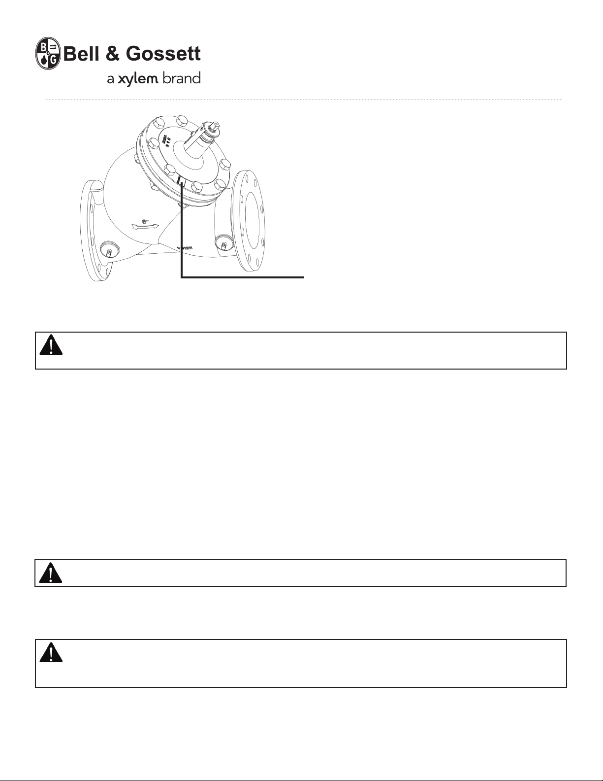
Warning Label Part Number V56846 Installed in this
location. If missing, it must be replaced.
INSTALLER: PLEASE LEAVE THIS MANUAL FOR THE OWNER’S USE.
SAFETY INSTRUCTIONS: This safety alert symbol will be used in this manual to draw attention to safety related
instructions. When used, the safety alert symbol means ATTENTION! BECOME ALERT! YOUR SAFETY IS
INVOLVED! FAILURE TO FOLLOW THESE INSTRUCTIONS MAY RESULT IN A SAFETY HAZARD!
Description
Bell & Gossett Circuit Setter Balance Valves are precision engineered valves which function as precise system balancing valves
and highly accurate flow meters. They will also function as a positive shutoff service valve. They are equipped with an easy
to operate memory stop feature which allows the circuit setter to be closed for system service and yet to be returned to the
previously determined setting.
Operational Limits
Maximum Operating Pressure - Flanged: 175 psig (1207 kPa), Maximum Operating Pressure - Grooved: 300 psig
(2068 kPa), Maximum Operating Temperature: 250°F (121°C)
Installation Instructions
1.To retain calibrated accuracy, a minimum length of unrestricted straight pipe equivalent to 5-pipe diameters up-stream and
2-pipe diameters downstream must be maintained immediately adjacent to the Circuit Setter Balance Valves.
2.Circuit Setter Balance Valves are unidirectional and must be installed with the arrow cast on body of valve pointing
indirection of flow. Bell & Gossett Circuit Setter Balance Valves may be installed either in vertical or horizontal pipe with valve
stem pointing up or down.
IMPORTANT: Bell &Gossett Circuit Setter Balance Valves are not recommended for use with meter connections
pointing down. Dirt will collect in the connections and foul up the readout valves and readout meters.
3.Circuit Setter Balance Valves are furnished with 125# ANSI cast iron flanges rated at 175 PSI (1207 kPa) or grooved
connectors rated at 300 PSI (2068 kPa) at 250° F (121° C). Companion ANSI flanges or grooved connectors should be selected
with suitable gaskets and bolting to withstand rated pressure and temperature. Bolts are to be properly torqued and
tightened in a crisscross pattern.
WARNING: The use of improper mating flanges, connectors, gaskets or bolting can cause flange or connector failure
resulting in the loss of hot or cold system fluid. Use only companion cast iron ANSI flanges or connectors with
appropriate gaskets and properly tightened bolts. Failure to follow this instruction can result in serious personal
injury and/or property damage.
4.Check connections for leaks and re torque if necessary.
Operating Instructions
How to Use Bell & Gossett Circuit Setter to Establish Required System Flow
1.Place a wrench on the wrench flats on top of the Circuit Setter stem and open the Circuit Setter to the 100% open position.
Circuit Setter position (amount Circuit Setter is open or closed) can be read by the position of the indicator ring through the
nameplate slot. See Figure 1.
Page 2
WARNING: Hot water leakage can occur from readout valve during probe insertion and during hook up of readout
kit. Follow the instruction manuals supplied with readout probes and readout kits for safe use. Failure to follow
these instructions could result in serious personal injury and/or property damage.
IMPORTANT: If the system contains a liquid with a specific gravity and/or viscosity higher or lower than that of water,
apply the appropriate correction factor noted in these instructions to obtain the actual GPM for the system liquid.
CAUTION: Avoid excessive pressure drop. Do not throttle Circuit Setter to pressure drops above 25 ft. of H2O (7.6m
of water). Failure to follow this instruction may result in valve noise and valve damage which can result in additional
property damage.
IMPORTANT: If balancing at less than 50% stem rise position is required, and this is the primary balance valve, Bell
& Gossett recommends that the impeller be sized to produce design flow. This will reduce electrical energy
consumption.
WARNING: Hot water leakage can occur from readout valve during probe insertion and during hook up of readout
kit. Follow the instruction manuals supplied with readout probes and readout kits for safe use. Failure to follow this
instruction could result in serious personal injury and/or property damage.
CAUTION: Avoid excessive pressure drop. Do not throttle Circut Setter to pressure drops above 25ft. of H2O (7.6m of
water). Failure to follow this instruction may result in valve noise and damage which can result in property damage.
IMPORTANT: If balancing at less than 50% stem rise position is required, and this is the primary balance valve, Bell &
Gossett recommends that the impeller be sized to produce design flow. This will reduce electrical energy consumption.
Fig. 1
2.Energize the zone, circuit and/or system pump(s) as applicable so that fluid is flowing through the Circuit Setter.
3.Using Bell & Gossett model RP-250B readout probes, attach a Bell & Gossett differential pressure readout kit to the readout
valves on Circuit Setter balance valve.
4.Read the differential pressure across the Circuit Setter.
5.Refer to the 100% open pressure drop curve in the Curve Booklet for the size Circuit Setter installed and read the flow
corresponding to the measured pressure drop. The Cv shown on the curve may also be used to calculate the flow or to read the
flow from scale 5 on the Bell & Gossett System Syzer.
6.If the GPM does not agree with the specified (required) GPM, close the Circuit Setter accordingly. Repeating steps 5 and 6
until the required results have been achieved.
How to use the Memory Stop Feature
1.After the final adjustment of the Circuit Setter has been made,
loosen the memory stop locking screw.
2.Position the memory stop so that it is as far up on the Circuit
Setter stem as it will go.
3.Tighten memory stop locking screw.
4.Circuit Setter can now be closed for system service and then
returned to its present position after service has been completed.
How to use Bell & Gossett Circuit Setters to Proportionally
Balance a System
1.Open fully all Circuit Setters on a single pump system.
2.If more than one branch circuit is used, start the balance
procedure by reading all of the flows to the units in a branch.
Each unit (coil) should have its own Circuit Setter for flow
balancing. Using Bell & Gossett PR-250B readout probes,
sequentially attach a Bell & Gossett differential pressure Readout
Kit to the Readout Valves on each Circuit Setter Balance Valve. Refer
to the Curve Booklet to obtain flow based on pressure drop.
3.Calculate the ratio of the actual flow to the design flow for each unit in the branch. This is the proportional flow rate.
(Actual flow divided by design flow).
4.Select the Circuit Setter with the lowest proportional flow. This Circuit Setter is left in the full open position. Every other
Circuit Setter in the branch is then reset to the same proportional flow.
5.If there are additional branches, repeat the steps in 3 and 4 above for each branch.
6.After all branches have been proportionately balanced, measure the full open flows on the Circuit Setter Balance Valves
installed on the risers. Calculate the proportional ratio of each riser Circuit Setter and select the one with the lowest
proportional ratio. This Circuit Setter is left fully open and the other riser Circuit Setters are adjusted to this same ratio.
7.Adjust pump flow so that circuits are receiving their design flow. This can be accomplished by adjusting a Circuit Setter
Balance Valve installed on the pump discharge or by changing the pump impeller size.
Page 3

How to Use Bell & Gossett Circuit Setter Balance Valve as an Isolation Valve
1.Place a wrench on the wrench flats located on top of the Circuit Setter stem and rotate the stem until indicator ring indicates
the stem has reached the closed position. Apply additional torque to the stem until firm resistance in felt indicating the Circuit
Setter is closed.
2.Close the Isolation Valve on the other side of the equipment to be serviced. Allow system temperature to cool below 100°F
(37°C).
3.Open the drain valve to drain the system between the Circuit Setter and second Isolation Valve.
WARNING: Check for proper sealing when using the Circuit Setter as an Isolation Valve. If the seat is not sealing
properly, liquid will continue to flow from drain valves. In this case the Circuit Setter must be isolated from the
system and repaired. Failure to do so could result in serious personal injury and/or property damage.
Service Instructions
Periodically inspect the Circuit Setter for signs of leakage or corrosion.
WARNING: Corrosion or leakage are indications that the Circuit Setter may be about to cause serious damage. The
Circuit Setter must be replaced or serviced. Failure to follow this instruction can result in serious personal injury and/
or property damage.
Stem Packing Nut Leakage
If leakage occurs at the stem packing nut, tighten nut until leaking stops. If tightening will not stop leakage, proceed as follows:
1.Note the set position of the Circuit Setter valve opening (% Stem Rise). Loosen the memory stop and slide stop down to the
indicator ring. Refer to Figure 1.
2.Open the Circuit Setter to the full open position until resistance is felt on the stem. This will backseat the stem, keeping any
leakage to a minimum during the servicing of the stem packing.
3.Loosen and fully remove the packing nut (located at the base of stem) by turning it counterclockwise.
4.Inspect packing for damage or debris that may be present. Remove any debris that may be there.
5.Refer to parts list for proper packing. Place one or two additional packing in the packing recess and replace and snugly
tighten the packing nut.
6.Close Circuit Setter part way and check for leakage with system pressurized.
7.If leakage is present, tighten packing nut until leakage stops.
8.Reposition the valve stem per observation in Step #1.
Leakage Through the Circuit Setter Seat
If the Circuit Setter leaks in the shut off or closed position, the rubber seat may be replaced as follows:
WARNING: System fluid under pressure and/or temperature can be very hazardous. Isolate the Circuit Setter from
the piping system. Allow system temperature to cool below 100°F (37°C). Open a drain and vent all pressure from
Circuit Setter. Failure to follow this instruction can result in serious injury or death and/or property damage.
1.Open Circuit Setter so that it is not in the closed position.
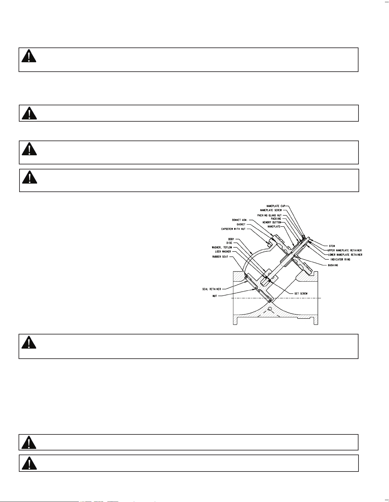
2.Remove the cap screws that hold the upper assembly to the Circuit Setter body. See Figure 1.
3.Lift the upper assembly out of the Circuit Setter body.
4.Inspect the seat pressed into the Circuit Setter body for damage. If damaged, Circuit Setter must be replaced. If it is not
damaged, proceed to step 5.
5.Remove the nut and washer that hold the rubber seat to the seat disc.
6.Remove the rubber seat and replace only with a genuine Bell & Gossett replacement.
CAUTION: Rubber materials other than those supplied by Bell &Gossett may fail prematurely. This could result in
personal injury and/or property damage when used as an isolation valve.
7.Replace the washer.
8.Add a drop of Loctite Grade 242 to threads and immediately install and securely tighten the retaining nut.
Size Nut Torque Requirements Size Nut Torque Requirements
4” 30 Ft. lbs. 8” 40 Ft. lbs.
5” 30 Ft. lbs. 10” 40 Ft. lbs.
6” 30 Ft. lbs. 12” 40 Ft. lbs.
9.Remove the gasket and thoroughly clean flange gasket surface at the body and cover.
10.Install new genuine Bell & Gossett gasket and replace the upper assembly into the Circuit Setter body.
CAUTION: Gasket materials other than those supplied by Bell & Gossett may fail prematurely. This could result in
personal injury and/or property damage.
11.Install the cap screws, securely tighten in a criss cross pattern.
12.Repressurize Circuit Setter and tighten cap screws as necessary if gasket leaks develop.
13.Return Circuit Setter stem to the preset position and return system to normal operation.
Lubrication of Stem Thread
Periodically lubricate the Circuit Setter stem threads with a good grade of grease such as Shell Alvania EP#2.
Page 4

B & G Circuit Setter Correction Factors for Viscosity and Specific Gravity
Xylem Inc.
8200 N. Austin Avenue
Morton Grove, Illinois 60053
Phone: (847) 966-3700
Fax: (847) 965-8379
www.xyleminc.com/brands/bellgossett
Bell & Gossett is a trademark of Xylem Inc. or one of its subsidiaries.
© 2012 Xylem Inc. G10047E April 2012
 Loading...