

Page 1
INSTRUCTION MANUAL
DN0412
REVISION C
Hoffman Specialty
®
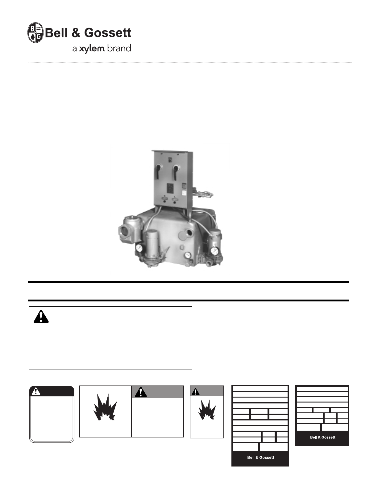
Vented Boiler Feed Units
Series HCM,™ HSM
HCM Boiler Feed Units
INSTALLER: PLEASE LEAVE THIS MANUAL FOR THE OWNER’S USE.
SAFETY
INSTRUCTIONS
This safety alert symbol will be used in this manual and on
the unit safety instruction decals to draw attention to safety
related instructions. When used, the safety alert symbol
means ATTENTION! BECOME ALERT! YOUR SAFETY IS
INVOLVED! FAILURE TO FOLLOW THESE INSTRUCTIONS
MAY RESULT IN A SAFETY HAZARD.
CAUTION
DO NOT RUN PUMP DRY,
SEAL DAMAGE MAY OCCUR.
INSPECT PUMP SEAL
REGULARLY FOR LEAKS,
REPLACE AS REQUIRED.
FOR LUBRICATION
REQUIREMENTS, CONSULT
SERVICE INSTRUCTIONS.
FAILURE TO FOLLOW
INSTRUCTIONS COULD
RESULT IN INJURY OR
PROPERTY DAMAGE.
P70644 ALL UNITS
P70644
EXPLOSIBLE
(2) All Units
DN0483 (Small) - DN0484 (Large)
WARNING
DO NOT PRESSURIZE TANK.
ISOLATE TANK DURING LEAK TEST.
DO NOT RESTRICT VENT.
DO NOT PLUG OVERFLOW.
OPEN INLET VALVES SLOWLY.
DO NOT USE AS A FLASH TANK.
FAILURE TO FOLLOW
INSTRUCTIONS COULD RESULT
IN SERIOUS INJURY OR DEATH.
If the decals as noted below are missing or are illegible contact your local B&G representative for a replacement.
1. Electrical connections to be made by qualified Electrician in
accordance with all National, State and Local codes.
2. Motor must have properly sized starter with properly sized
heaters to provide overload and undervoltage protection.
3. If pump, motor or piping are operating at extremely high or
low temperatures, guarding or insulation is required.
4. Operating personnel should be trained in the operation of
boiler feed units.
WARNING
EXPLOSIBLE
ISOLATE TANK
DURING LEAK TEST
(2) All Units
DN0485 (Small)
DN0486 (Large)
TM
SERIES
MODEL
SERIAL
GPM PSI PUMP
CFM IN HG. PUMP
DWGS
POWER V. PH. HZ60
CONTROL V. PH. 1 HZ60
TOTAL LARGEST MOTOR
F.L. AMP F.L. AMP
DN0016
TM
Morton Grove, Illinois 60053
SERIES
MODEL
SERIAL
GPM PSI PUMP
POWER V. PH. HZ60
CONTROL V. PH. 1 HZ60
TOTAL LARGEST MOTOR
F.L. AMP F.L. AMP
DN0019
UNITS LESS PANEL
TM
TM
Morton Grove, Illinois 60053
DN0019
DN0016
UNITS WITH PANEL
Page 2
Page 3
3
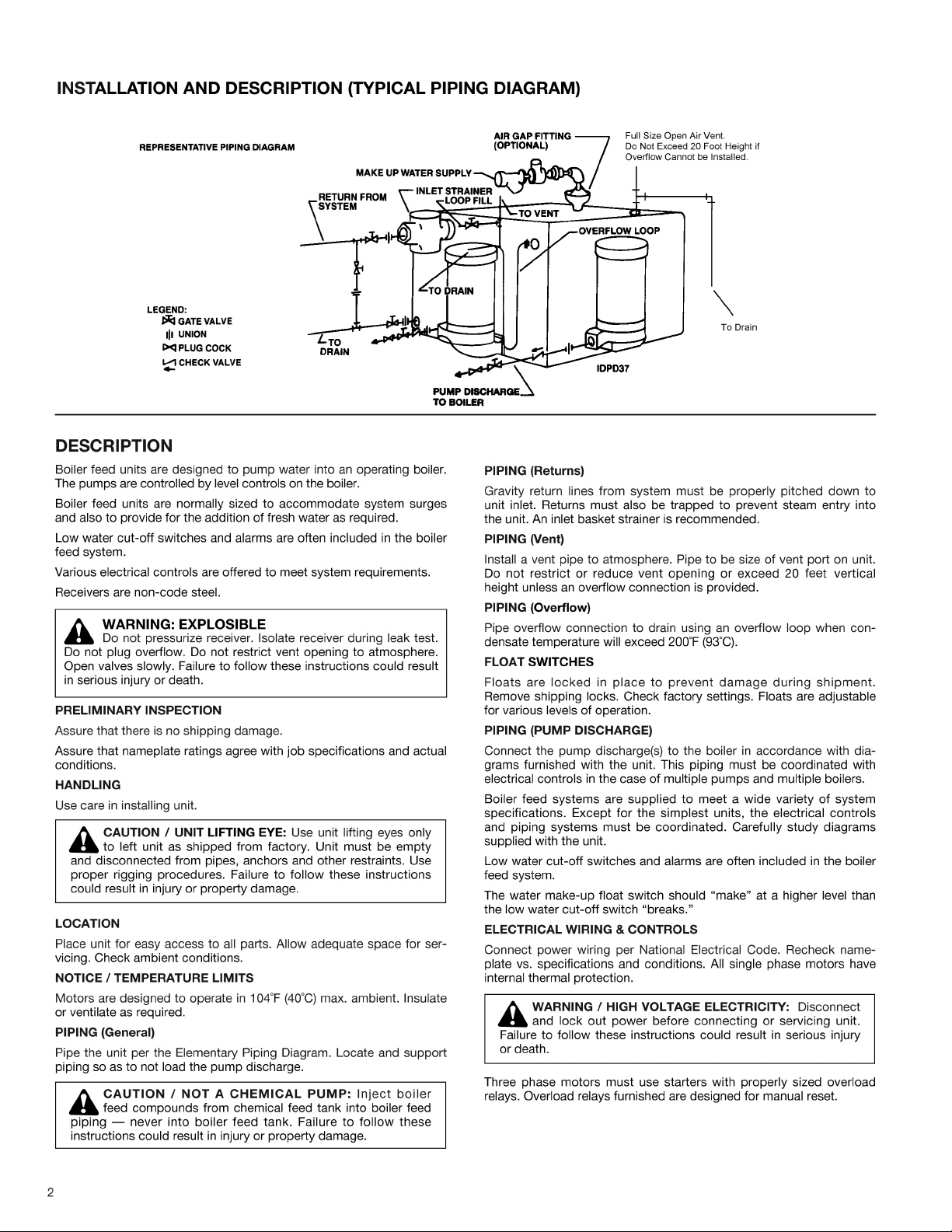
PUTTING THE UNIT INTO SERVICE
1. Assure that the unit is piped in accordance with instructions on
page 2.
2. Isolate tank before performing any system leak test. Do not pressurize the tank as part of the leak test. Failure to do this can result
in serious injury or death.
3. Check floats and alternators for free operation.
4. Check power leads in accordance with wiring diagram enclosed in
control cabinet (when furnished).
5. Install drain plugs.
6. Fill receiver half full of water to prime pump(s) and prevent possible damage to pump seals. Avoid freezing conditions after unit
receiver has been filled.
7. Check for proper rotation of all three phase motors. Rotation must
be clockwise looking down on the motor as indicated by directional arrow on pump casting. If pump runs backwards, interchange two wires (3 phase only).
8. Throttle plug cock in discharge line until pressure at pump (while
pump is discharging) approaches pump rated pressure. Tighten
plug nut to secure adjustment.
9. Connect the water make-up assembly to city water. Use piping at
least as large as the valve piping provided. Provide a manual fill
valve if not included on the unit.
10. Boiler Level Controls — Assure that the controls on and related to
the boiler match the control systems provided on the unit (see the
wiring diagram furnished) (applicable when electrical control panel
is furnished).
11. Check that the pump discharge pressure exceeds the maximum
operating pressure of the boiler.
12. Manually move the make-up water float indicator and assure that
the make-up solenoid admits water.
13. Manually move the low water cut-off float switch indicator to
check for pump shut-off.
14. Remove start-up label (below) from panel (if applicable) after complying with instructions.
15. If possible, observe operation thru several cycles.
OPERATION AND MAINTENANCE
Operators must be familiar with all sections of this manual to under-
stand the operation of the unit.
Hot water, steam and electricity can be hazardous.
Check motor nameplate for any lubrication requirements. Pumps
require no lubrication.
NOTICE / AUTO RESTART
Single phase motors will restart automatically after thermal overload
protector trips.
Overload thermal relays in starters must be reset manually.
A properly installed unit should function unattended for long periods
of time. Periodic checks to assure proper operation are highly recommended. Refer to trouble shooting section when necessary.
A variety of control options are available and are furnished in accordance with user specifications. Refer to wiring diagrams (when furnished) to determine control switch settings.
The inlet strainer (when furnished) is intended to protect the pump and
system. Periodic cleaning should be included in the maintenance
schedule. Check frequently in new systems.
WARNING / HIGH VOLTAGE: Disconnect and lock out
power before connecting or servicing unit. Failure to follow
these instructions could result in serious injury or death.
WARNING / MAINTAIN BOILER SAFETY FEATURES:
When connecting the boiler feed unit to the boiler, assure
that all boiler safety controls (burner cutoff, etc.) are and remain
operational. With certain control arrangements, dedicated boiler
controllers are required for the boiler feed pumps. Failure to follow these instructions could result in serious injury, death or
extensive property damage.
CAUTION: DO NOT RUN DRY.
SEAL DAMAGE MAY OCCUR.
Inspect pump seal regularly for leaks. Replace as required.
Failure to follow these instructions could result in injury or property damage.
CAUTION / DO NOT REVERSE: Reverse operation can
cause extensive damage to pumps. Jog the motor to test
from direction of rotation. Failure to follow these instructions
could result in injury or property damage.
WARNING / HIGH VOLTAGE: Disconnect and lock
out power before connecting or servicing unit. Failure to
follow these instructions could result in serious injury or death.
WARNING / EXPLOSIBLE: The installed boiler feed
unit becomes an integral part of the boiler system. Boiler
operation and maintenance requires specific skills and training
and may require licensing or certification. The boiler feed unit
must be operated and maintained so as not to jeopardize the
boiler operation. Failure to follow these instructions could result
in serious injury, death or extensive property damage.
SAFETY INSTRUCTIONS
SEE COVER OF THIS MANUAL.
CAUTION / SUBSEQUENT DAMAGE: A unit showing
symptoms of possible problems (overflow, noise, leaks,
vibrations, continual operation, etc.) must be corrected immediately. Failure to follow this instruction may result in full liability for
subsequent injury or property damage.
WARNING: EXPLOSIBLE
Do not pressurize receiver. Isolate receiver during leak test.
Do not plug overflow. Do not restrict vent opening to atmosphere.
Open valves slowly. Failure to follow these instructions could result
in serious injury or death.
WARNING: EXPLOSIBLE
Do not pressurize receiver. Isolate receiver during leak test.
Do not plug overflow. Do not restrict vent opening to atmosphere.
Open valves slowly. Failure to follow these instructions could result
in serious injury or death.
ELECTRICIAN/INSTALLER/OPERATOR
REMOVE AND DESTROY THIS TAG AFTER —
1. ASSURING THAT ALL PUMPS ROTATE CLOCKWISE PER ARROWS CAST ON VOLUTES. (JOG
PUMP MOMENTARILY TO TEST – INTERCHANGE ANY TWO MOTOR POWER WIRES TO
REVERSE 3PH MOTORS.)
2. ASSURING THAT SHIPPING LOCKS HAVE BEEN REMOVED FROM ALL FLOAT SWITCHES.
Page 4

4
TROUBLE SHOOTING PROCEDURES
All units are thoroughly tested at the factory before shipment. They
should operate satisfactorily without further adjustment if properly
installed and provided they have not been damaged by rough handling
in transit. If system or unit performance is not satisfactory, refer to the
following check list.
Pump Will Not Start
1. The power supply has been interrupted, disconnect switch is open
or selector switch is improperly positioned.
2. Incorrect voltage for motor. Check voltage and wiring with motor
characteristics.
3. Incorrect starter coil for power supply.
4. The overload relays and the starter have tripped out and must be
reset. Ambient temperature may be too high.
5. Check pump controls or other controls for proper operation.
6. Wiring to control cabinet is incorrect or connections are loose.
7. The basket strainer is dirty thus restricting flow into the receiver.
Clean periodically.
8. Boiler is full or boiler control switch is defective.
9. The low water cut-off float switch is open due to low water, incorrect adjustment or failure.
Pumps Runs Continuously
1. Pump is running backward. Rotation of three phase motors may be
corrected by interchanging any two of the three wires. Rotation
should be clockwise looking down on motor.
2. Steam traps are blowing through causing condensate to return at
excessive temperatures. This may reduce the capacity of pump
below its rating. Traps should be repaired or replaced.
3. Pump discharge pressure is less than operating pressure of the
boiler.
4. The total required pressure at the pump discharge is greater than
the pressure for which the pump was designed. Check the total
pressure which includes atmospheric pressure, the friction head
and the static head.
5. A valve in the discharge line is closed or throttled too tightly. Check
valve is installed backwards.
6. The impeller eye is clogged.
7. Pump is too small for system.
Boiler Feed Pump is Noisy
1. The pump is working against a lower pressure than designed for.
While pump is discharging, adjust plug cock in discharge line until
pressure at pump approaches pump rated pressure.
2. Excessive condensate temperature. Correct system conditions. However, this applies to certain units only; others are designed to handle
boiling water.
3. Magnetic hum or bearing noise in motor. Consult motor manufacturer's authorized serviced station nearest unit location.
4. Starter chatters. Trouble is caused by low line voltage, poor connections, defective starter coil, or burned contacts.
5. Pump is running backward.
The System is Noisy
1. Banging in the steam mains is usually caused by steam “imploding”
in condensate lying in low points in lines. These problems can be
eliminated by dripping low points, properly supporting the pipe, or
by increasing the pitch of the lines.
2. Improper dripping of the steam mains and risers; where there is a
rise in the steam main, or where it branches off into a riser, a drip
trap must be installed in the drain line.
3. The piping is too small to drain properly.
4. A defective steam trap is holding condensate in steam supply line.
5. Defective check valve permits steam, to vent thru pump into the
boiler feed tank.
6. A priming boiler is discharging water with the steam. Consult boiler
manufacturer.
Excessive Water Overflow From Unit
1. Receiver sized too small to accommodate system surges.
2. Water make-up valve open or float set too high.
3. Water make-up valve leaks.
Morton Grove, Illinois 60053
TM
SERIES HCM
MODEL
SERIAL
GPM PSI PUMP
CFM IN HG. PUMP
DWGS
POWER V. PH. HZ 60
CONTROL V. PH. 1 HZ 60
TOTAL LARGEST MOTOR
F.L. AMP F.L. AMP
DN0016
DEALER SERVICING
If trouble occurs that cannot be rectified, contact your local B&G rep-
resentative. He will need the following information in order to give you
assistance.
1. Complete nameplate data of pump and motor. SEE RATING
NAMEPLATE.
2. Suction and discharge pipe pressure gauge readings.
3. Ampere draw of the motor.
4. A sketch of the pump hook-up and piping.
5. Provide complete information on boiler control switches and any
motorized or solenoid valves in the boiler feed piping.
HOFFMAN SPECIALTY
®
Page 5

5
These close coupled vertical centrifugal pumps are equipped with
mechanical seals. If system has not been properly cleaned prior to
installation of pump, foreign matter such as dirt, pipe scale, core sand,
etc. may clog the impeller and damage the seal. A strainer is recommended in return line to pump.
Pump must not be operated dry. Seals
may be damaged if operated without water present.
1. Close inlet line gate valve and operate pump momentarily to
remove as much liquid as possible from pump. Close discharge
line gate valve.
2. Shut-off and lock-out power.
3. Disconnect wiring to motor.
4. Make sure unit is cool enough that pump can be handled safely.
Open receiver drain to remove remaining liquid.
5. Loosen the motor to pump volute fasteners. Assure that pressure
is relieved per caution note.
6. Remove four capscrews (7) holding pump case to motor and lift
motor and impeller out of pump case.
7. Remove pump/motor assembly and place on work bench.
8. Hold top end of motor shaft with large screwdriver via screwdriver
slot in shaft and back off impeller (counter clockwise) with a rectangular bar or other flat tool inserted between the vanesof the
impeller.
9. Remove the rotating part of the mechanical seal from the end of
the shaft.
10. Remove seal holder (2) with stationary ceramic part of mechanical
seal and cup rubber from the end of the shaft.
11. Remove stationary ceramic part of mechanical seal and cup rubber from recess in seal holder.
12. To install new seal, proceed as follows: Clean recess in seal
holder thoroughly. Orient motor so that conduit opening on motor
is to the left when looking at the motor shaft. Replace seal holder
on the face of the motor maintaining concentricity with motor
face. Place new ceramic part of seal in the cup rubber over motor
shaft and press firmly into recess of seal holder by hand, making
certain both parts bottom evenly. If assembly cannot be bottomed
with fingers place a wooden or cardboard tube over shaft onto
ceramic and push into place. Using a clean, lint-free cloth, wipe
the mating surfaces of the seal clean of any foreign matter.
Moisten the carbon section of the rotating part of the seal and
place onto shaft to seat against the ceramic. Place seal spring
onto shaft.
13. Hold motor shaft as described in #8 and replace the impeller on
the shaft (clockwise rotation) making sure it is tight.
14. Orient motor for pump reassembly with conduit opening to the
left. When mounting the pump case, discharge should be 90˚ to
the right of the conduit opening on motor. Use care to insure tight
gasket fit to prevent water leakage.
15. Replace four capscrews (7). Tighten down capscrews evenly to
avoid damage.
16. Reconnect pump bleed line (where applicable) and motor wiring.
17. Close drain and slowly open inlet valves. See warning.
18. Jog to check motor rotation. See caution.
19. Observe operation thru several cycles.
PUMP SERVICE INSTRUCTIONS FOR 609PF CENTRIFUGAL PUMPS
WARNING / HIGH VOLTAGE: Disconnect and lock out
power before connecting or servicing unit. Failure to follow
these instructions could result in serious injury or death.
CAUTION / HOT SURFACES: Surfaces are hot when
system is in operation. Do not touch hot receiver, let unit
cool before servicing. Failure to follow these instructions could
result in injury or property damage.
CAUTION / PRESSURIZED SYSTEM: Operating system
may contain very hot water under pressure. Close inlet and
open drains before servicing. When servicing, loosen screws and
move components to assure pressure is relieved before remov-
ing screws. Keep drains open during servicing. Failure to follow
these instructions could result in injury or property damage.
1. Motor
2. Seal Holder
3. Seal
4. Impeller
5. Gasket
6. Case
7. Capscrew
(motor to
volute)
8. Wear Ring
9. Pipe Plug
10. Slinger
1
10
7
3
4
8
6
9
5
2
CAUTION: DO NOT RUN DRY.
SEAL DAMAGE MAY OCCUR.
Inspect pump seal regularly for leaks. Replace as required. Failure
to follow these instructions could result in injury or property
damage.
CAUTION / DO NOT REVERSE: Reverse operation can
cause extensive damage to pumps. Jog the motor to test
for direction of rotation. Failure to follow these instructions could
result in injury or property damage.
WARNING: EXPLOSIBLE
Do not pressurize receiver. Isolate receiver during leak test.
Do not plug overflow. Do not restrict vent opening to atmosphere.
Open valves slowly. Failure to follow these instructions could result
in serious injury or death.
Page 6

Close coupled centrifugal pumps are designed for years of trouble
free service. Units have mechanical shaft seals.
1. Close inlet gate valve and operate pump momentarily to remove
as much liquid as possible from pump. Close discharge line gate
valve.
2. Shut-off and lock out power.
3. Make sure unit is cool enough that pump can be handled safely.
Open drain to remove remaining liquid.
4. Carefully remove pump drain plug and bleed line. Wait for complete drainage.
5. Loosen the motor bracket to pump volute capscrews. Assure that
the pressure is relieved per caution note.
6. Complete the removal of the hardware. Remove pump/motor
assembly and place on work bench.
7. Remove self locking stainless steel capscrews and stainless steel
washer (or self locking brass cap nut and washer) that secure the
impeller in place.
8. To remove impeller from motor shaft proceed as follows:
(1) Keyed Shafts. Remove impeller with gear puller or other
means which will not damage impeller or bend motor shaft.
(2) Threaded Shafts. Hold end of motor shaft opposite pump with
large screwdriver or other suitable tool and back impeller off
with a rectangular bar or other flat tool inserted between the
vanes of the impeller.
9. Remove rotating part of seal from shaft, being careful not break
carbon face.
10. Remove capscrews holding motor bracket to motor and remove
bracket.
11. Remove stationary part of seal assembly, being careful not to chip
or break ceramic seal.
12. To install seal proceed as follows:
(1) Clean recess in bracket thoroughly. Coat recess and “rubber”
portion of seat with soap solution. Press seat into recess firmly
by hand making certain both parts bottom evenly. If seal cannot be bottomed with fingers place cardboard shipping disc
on ceramic and force into place with flat tool.
(2) Carefully place bracket in position on motor shaft without
displacing ceramic seat and secure bracket to motor with
capscrews.
(3) Place motor vertically with pump end up. Do not attempt
assembly of seal and impeller with shaft horizontal.
(4) The “carbon” of rotating part of seal should not be loose. If it
is, hold in place with grease, Using clean, lint free cloth, wipe
mating surfaces perfectly clean. Soap shaft and push seal
onto shaft so that carbon will contact ceramic seal. If spacer is
required, use grease to cause spacer to adhere to bottom of
seal after seal has been put on shaft, Be sure spacer is on
larger diameter of shaft so that will not catch between shoulder and impeller.
13. Replace impeller on shaft. Replace stainless steel washer and
secure impeller with capscrew or cap nut.
14. Place new gasket on pump volute and reassemble motor and
pump subassembly on pump volute.
15. Reconnect pump bleed line and motor wiring.
16. Close drain and slowly open inlet valves. See warning.
17. Jog to check motor rotation. See caution.
18. Observe operation thru several cycles.
6
PUMP SERVICE INSTRUCTIONS FOR CENTRIFUGAL PUMPS (EXCEPT ‘B’ OR 609)
Vertical mounting puts motor above floor direct and water
CAUTION: PRESSURIZED SYSTEM
Operating system may contain very hot water. Close inlet
and open drains before servicing. When servicing,
loosen screws
and move components to assure pressure is relieved before
removing screws. Keep drains open during servicing. Failure to fol-
low these instructions could result in injury or death.
CAUTION: HOT SURFACE
Surfaces are hot when system is in operation. Do not touch
hot receiver, let unit cool before servicing. Failure to follow these
instructions could result in serious injury or death.
WARNING: HIGH VOLTAGE
Disconnect and lock out power before connecting servicing
unit. Failure to follow these instructions could result in serious
injury or death.
WARNING: EXPLOSIBLE
Do not pressurize receiver. Isolate receiver during leak test.
Do not plug overflow. Do not restrict vent opening to atmosphere.
Open valves slowly. Failure to follow these instructions could result
in serious injury or death.
CAUTION: DO NOT REVERSE
Reverse operation can cause extensive damage to pumps.
Jog the motor to test for direction of rotation. Failure to follow
these instructions could result in injury or property damage.
CAUTION: DO NOT RUN DRY.
SEAL DAMAGE MAY OCCUR.
Inspect pump seal regularly for leaks. Replace as required. Failure
to follow these instructions could result in injury or property
damage.
VOLUTE
IMPELLER
THREADED
IMPELLER
WATER
SLINGER
MECHANICAL
SEAL
MOTOR BRACKET
WEAR RING
VIEW OF
2DPF03
Page 7

7
NOTES:
Page 8

Xylem
1) The tissue in plants that brings water upward from the roots;
2) a leading global water technology company.
We’re 12,700 people unied in a common purpose: creating innovative solutions
to meet our world’s water needs. Developing new technologies that will improve
the way water is used, conserved, and re-used in the future is central to our work.
We move, treat, analyze, and return water to the environment, and we help people
use water efciently, in their homes, buildings, factories and farms. In more than
150 countries, we have strong, long-standing relationships with customers who
know us for our powerful combination of leading product brands and applications
expertise, backed by a legacy of innovation.
For more information on how Xylem can help you, go to www.xyleminc.com
Xylem Inc.
8200 N. Austin Avenue
Morton Grove, Illinois 60053
Phone: (847) 966-3700
Fax: (847) 965-8379
www.bellgossett.com
Bell & Gossett is a trademark of Xylem Inc. or one of its subsidiaries.
© 2013 Xylem Inc. DN0412C April 2013
 Loading...