

Page 1
INSTRUCTION MANUAL
63/4
(171)
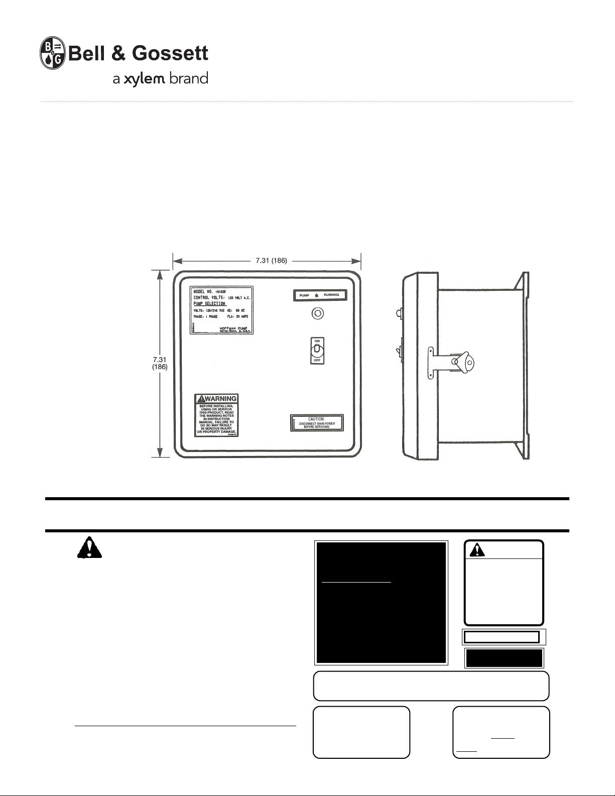
NEMA 4 ENCLOSURE
6x6x4.03
(152x152x110)
Dimensions in Inches (mm)
4 (102)
5
/
16 (8) Mounting Hole
(4 Places)
DN0178
REVISION B
Hoffman Specialty
®
Single Phase Simplex
Control Panel
B&G
Dimensions in Inches (mm)
INSTALLER:
PLEASE LEAVE THIS MANUAL FOR THE OWNER’S USE.
SAFETY
INSTRUCTIONS
This safety alert symbol will be used in this manual and on
the unit safety instruction decals to draw attention to safety
related instructions. When used, the safety alert symbol means
ATTENTION! BECOME ALERT! YOUR SAFETY IS INVOLVED!
FAILURE TO FOLLOW THE INSTRUCTIONS MAY RESULT IN
A SAFETY HAZARD.
If the decals as noted to the right are missing or are illegible contact your local Hoffman Pump representative for a
replacement.
1. Electrical connections to be made by a qualified Electrician
in accordance with National, State or Local codes.
2. Motor must be sized in accordance with contactor rating
and have internal overload and undervoltage protection.
MODEL NO. 161029
CONTROL VOLTS: 120 VOLT A.C.
PUMP SELECTION
VOLTS: 120/240 VAC HZ: 60 HZ
PHASE: 1 PHASE FLA: 20 AMPS
Bell & Gossett
M Illinois 60053orton Grove,
DN0444
USE COPPER WIRE ONLY
6 0°C INSULATION R ATING F OR A MPACITIES LESS T H A N 1 0 0 A
S80379
7 5°C INSULATION RATI NG FO R AMPACITIES GR EA TER T H A N 1 0 0 A
DNO442
WARNING
BEFORE INSTALLING,
USING OR SERVICING
THIS PRODUCT, READ
THE WARNING NOTES
AND INSTRUCTIONS
IN INSTRUCTION
MANUAL. FAILURE TO
DO SO MAY RESULT
IN SERIOUS INJURY
OR PROPERTY DAMAGE.
PUMP ✽ RUNNING
CAUTION:
DISCONNECT MAIN POWER
DN0445
BEFORE SERVICING
DNO443
CAUTION
G R D
US E TYPE FUSE
AMP
V56846
DN0430
Page 2
DESCRIPTION
The Hoffman Single Phase Simplex Electrical Control
Panel is designed to provide a reliable means of controlling
one 120 volt or 230 volt (3 wire) single phase pump installation that does not exceed a FLA of 20 amps
.
OPERATION AND MAINTENANCE
Operators must be familiar with all sections of this manual
to understand the operation of the unit.
Hot Water, steam and electricity can be hazardous.
PRELIMINARY INSPECTION
Assure that there is no shipping damage.
Assure that the nameplate ratings agree with the job spec-
ifications and actual conditions.
Assure all connections are secure and made per NEC
requirements.
HANDLING
Use care in installing unit.
LOCATION
Place unit for easy access.
Allow adequate space for servicing. Check ambient
conditions.
Notice: Insulation temperature limits. Ventilate as required.
ELECTRICAL WIRING AND CONTROLS
Connect power wiring per NEC. Recheck nameplate vs.
specifications and conditions.
WARNING: HIGH VOLTAGE ELECTRICITY
Disconnect and lock out power before connecting or
servicing unit. Failure to follow these instructions could
result in serious injury or death.
PUTTING THE UNIT INTO SERVICE
Assure that the main power has been disconnected.
SAFETY INSTRUCTIONS
See Cover of this Manual.
WARNING: HIGH VOLTAGE ELECTRICITY
Disconnect and lock out power before connecting or
servicing unit. Failure to follow these instructions could
result in serious injury or death.
NOTICE / AUTO RESTART
Single phase motors will restart automatically after thermal
overload protector trips.
A properly installed unit should function unattended for
long periods of time. Periodic checks to assure proper
operation are highly recommended. Refer to trouble shooting section when necessary.
Refer to wiring diagrams to determine control switch
settings.
CAUTION: SUBSEQUENT DAMAGE
A unit showing symptoms of possible problems must
be corrected immediately. Failure to follow these instruc-
tions could result in full liability for subsequent injury or
property damage.
UNIT WIRING
WARNING: HIGH VOLTAGE ELECTRICITY
Disconnect and lock out power before connecting or
servicing unit. Failure to follow these instructions could
result in serious injury or death.
WARNING: HIGH VOLTAGE ELECTRICITY
Disconnect and lock out power before connecting or
servicing unit. Failure to follow these instructions could
result in serious injury or death.
Wire unit per National Electrical Code. See representative
wiring diagrams.
Observe operation of unit through several cycles.
Select the required configuration for the control panel to fit
the application. CAUTION: Verify that the incoming voltage
and the motor voltage correspond to the configuration of
the panel. Rewire jumper terminals if necessary.
Disconnect all power.
Identify incoming power and motor voltage configuration
from the Selection Chart below.
SELECTION CHART
Incoming Motor Connect Power Connect Pump Motor Jumper Connect Float Control
Voltage Voltage to Terminals to Terminals Terminals to Terminals
230/1/60 230/1/60 N, L2, L1 T1, T2 — L1, 2
115/1/60 115/1/60 L2, L1 T1, T2 N, L2 L1, 2
2
Page 3

ELEMENTARY DIAGRAM
SINGLE PHASE SIMPLEX CONTROL PANEL
WIRING / CONNECTIONS
WARNING: HIGH VOLTAGE ELECTRICITY
Panel remains fully energized at all times, unless
incoming power is disconnected. Disconnect and lock out
power before connecting or servicing unit. Failure to follow
these instructions could result in serious injury or death.
Wire incoming power to the terminals identified in the
Selection Chart on page 2.
Connect electrical ground wire to ground lug.
Wire the float switch.
Wire pump motor to the terminals identified in the
Selection Chart. Connect all necessary ground wires to the
ground lug. Connect ground lug to a good earth ground.
Check pump motor before installation for proper rotation.
Re-wire motor is necessary. Re-connect incoming power.
TYPICAL SEQUENCE OF OPERATION
1. When the float control “makes,” incoming electrical power
is supplied to the pump “ON-OFF” selector switch.
2. With the selector switch in the “ON” position the contactor
coil and the “Pump Run” pilot light will be energized.
3. When the contactor coil is energized, electrical power is
fed to the pump motor.
3
Page 4

TROUBLE SHOOTING
SYMPTOM PROBLEM SOLUTION
Pump will not start Incoming power not connected. Connect incoming Power.
Float control not “Made”. Operate system to “Make” Float Control.
Pump “ON-OFF” Switch not ON. Turn ON switch.
Fuse Blown. Replace fuse per label in enclosure.
Pump runs but light doesn’t light Blown pilot light. Replace pilot light.
DEALER SERVICING
If trouble occurs that cannot be rectified, contact your local
B&G representative. He will need the following information
in order to give you assistance.
1. Complete nameplate data of panel.
2. Voltage, phase, and FLA of motor.
3. Actual ampere draw of motor.
Xylem Inc.
8200 N. Austin Avenue
Morton Grove, Illinois 60053
Phone: (847) 966-3700
Fax: (847) 965-8379
www.xyleminc.com/brands/bellgossett
Bell & Gossett is a trademark of Xylem Inc. or one of its subsidiaries.
© 2013 Xylem Inc. DN0178B July 2013
 Loading...