

Page 1
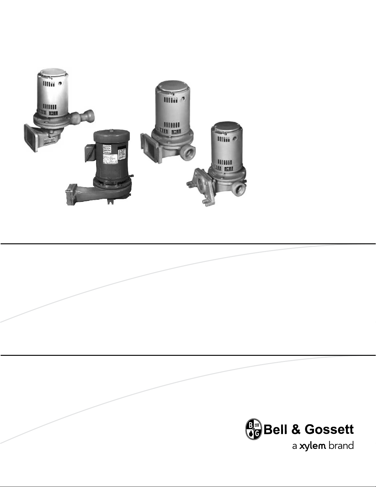
Serie B35
Installation,
Operation, and
Maintenance Manual
Serie C35
Serie C17
Domestic® Pump Centrifugal Pumps
Series B35, C17, C35
Page 2

Page 3

Table of Contents
Introduction and Safety.........................................................................................................................3
Introduction..........................................................................................................................................3
Safety.....................................................................................................................................................3
Safety terminology and symbols....................................................................................................3
User safety.........................................................................................................................................4
Environmental safety........................................................................................................................5
Product warranty.................................................................................................................................6
Transportation and Storage..................................................................................................................7
Inspect the delivery.............................................................................................................................7
Inspect the package.........................................................................................................................7
Inspect the unit..................................................................................................................................7
Lifting....................................................................................................................................................7
Long-term storage...............................................................................................................................7
Product Description...............................................................................................................................8
General description............................................................................................................................8
Operational specifications.................................................................................................................8
Nameplate information.......................................................................................................................9
Table of Contents
Installation.............................................................................................................................................10
Preinstallation....................................................................................................................................10
Pump location guidelines..............................................................................................................10
Piping checklist...............................................................................................................................10
System conditions..........................................................................................................................11
Connect the wiring............................................................................................................................11
Commissioning, Startup, Operation, and Shutdown......................................................................12
Prepare for startup............................................................................................................................12
Start the pump...................................................................................................................................12
Pump operation precautions...........................................................................................................13
Shut down the pump........................................................................................................................13
Maintenance.........................................................................................................................................14
General maintenance guidelines....................................................................................................14
Disassembly.......................................................................................................................................14
Disassembly precautions...............................................................................................................14
Drain the pump...............................................................................................................................15
Disassemble the Series B35 pump..............................................................................................15
Disassemble the Series C17 and C35 pump (except model 609)...........................................16
Disassemble the Series C35 model 609PF.................................................................................17
Reassembly........................................................................................................................................17
Install the mechanical seal (except Series C35 model 609)......................................................17
Install the mechanical seal (Series C35 model 609PF)..............................................................17
Assemble the Series B35 pump...................................................................................................18
Assemble the Series C17 and C35 pump...................................................................................19
Assemble the Series C35 model 609PF pump...........................................................................21
Complete the reassembly.............................................................................................................21
Troubleshooting...................................................................................................................................23
The pump does not start..................................................................................................................23
Pump capacity is reduced................................................................................................................23
Domestic® Pumps Centrifugal Pumps Series B35, C17, C35 Installation, Operation, and Maintenance Manual 1
Page 4

Table of Contents
The pump makes noise....................................................................................................................24
Dealer servicing.................................................................................................................................24
2 Domestic® Pumps Centrifugal Pumps Series B35, C17, C35 Installation, Operation, and Maintenance Manual
Page 5
Introduction and Safety
Introduction
Purpose of this manual
The purpose of this manual is to provide necessary information for:
• Installation
• Operation
• Maintenance
CAUTION:
Read this manual carefully before installing and using the product. Improper use of the
product can cause personal injury and damage to property, and may void the warranty.
NOTICE:
Save this manual for future reference, and keep it readily available at the location of the
unit.
Introduction and Safety
Safety
WARNING:
•
The operator must be aware of safety precautions to prevent physical injury.
• Any pressure-containing device can explode, rupture, or discharge its contents if it is
over-pressurized. Take all necessary measures to avoid over-pressurization.
• Operating, installing, or maintaining the unit in any way that is not covered in this manual
could cause death, serious personal injury, or damage to the equipment. This includes
any modification to the equipment or use of parts not provided by Xylem. If there is a
question regarding the intended use of the equipment, please contact a Xylem
representative before proceeding.
• This manual clearly identifies accepted methods for disassembling units. These methods
must be adhered to. Trapped liquid can rapidly expand and result in a violent explosion
and injury. Never apply heat to impellers, propellers, or their retaining devices to aid in
their removal.
• Do not change the service application without the approval of an authorized Xylem
representative.
CAUTION:
You must observe the instructions contained in this manual. Failure to do so could result in
physical injury, damage, or delays.
Safety terminology and symbols
About safety messages
It is extremely important that you read, understand, and follow the safety messages and
regulations carefully before handling the product. They are published to help prevent
these hazards:
• Personal accidents and health problems
• Damage to the product
• Product malfunction
Domestic® Pumps Centrifugal Pumps Series B35, C17, C35 Installation, Operation, and Maintenance Manual 3
Page 6
Introduction and Safety
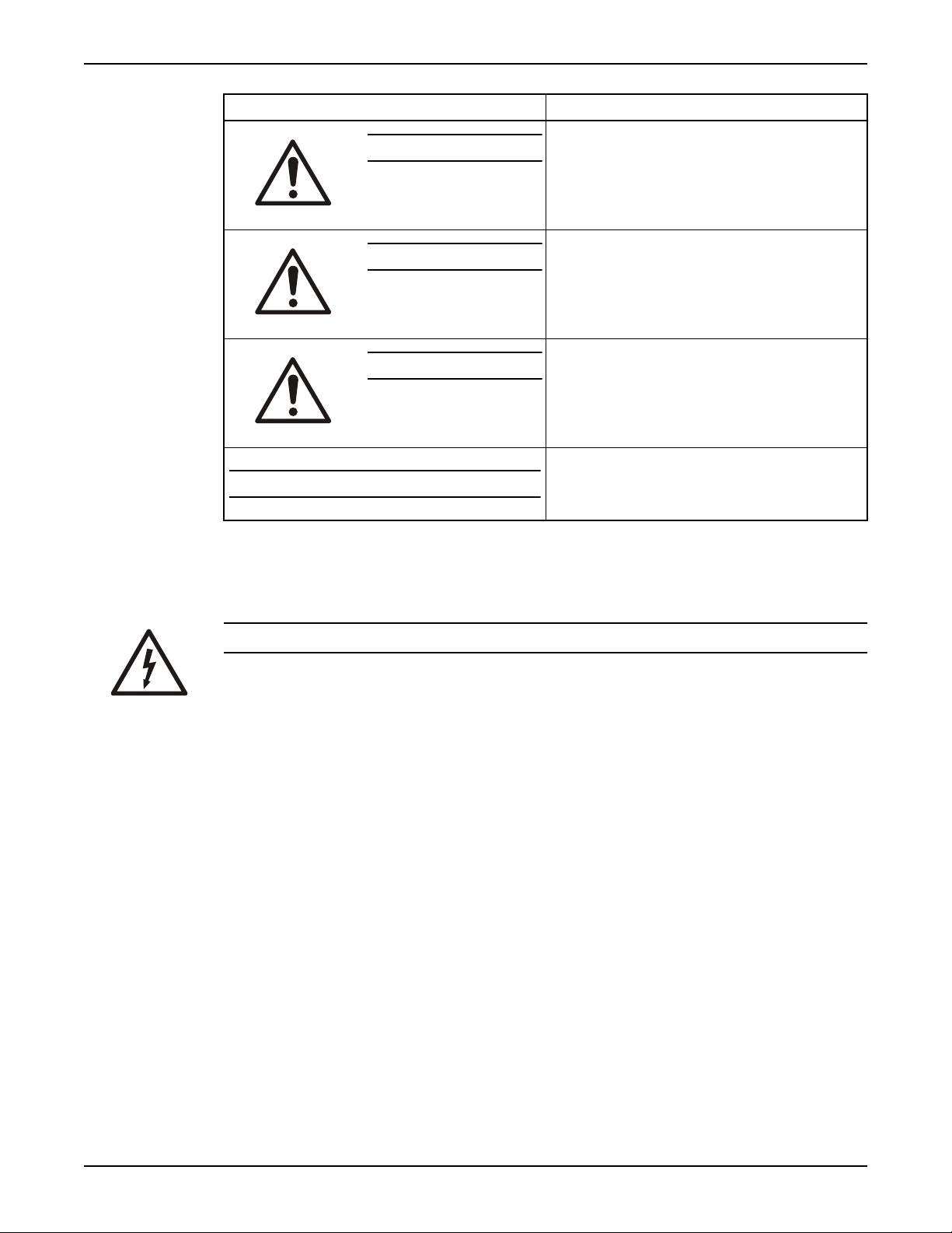
Hazard levels
Hazard level Indication
Hazard categories
DANGER:
WARNING:
CAUTION:
NOTICE:
Hazard categories can either fall under hazard levels or let specific symbols replace the
ordinary hazard level symbols.
Electrical hazards are indicated by the following specific symbol:
A hazardous situation which, if not avoided, will result in
death or serious injury
A hazardous situation which, if not avoided, could result
in death or serious injury
A hazardous situation which, if not avoided, could result
in minor or moderate injury
• A potential situation which, if not avoided, could
result in undesirable conditions
A practice not related to personal injury
•
User safety
General safety rules
Safety equipment
Electrical Hazard:
These are examples of other categories that can occur. They fall under the ordinary hazard
levels and may use complementing symbols:
•
Crush hazard
• Cutting hazard
• Arc flash hazard
These safety rules apply:
• Always keep the work area clean.
• Pay attention to the risks presented by gas and vapors in the work area.
• Avoid all electrical dangers. Pay attention to the risks of electric shock or arc flash
hazards.
• Always bear in mind the risk of drowning, electrical accidents, and burn injuries.
Use safety equipment according to the company regulations. Use this safety equipment
within the work area:
• Hard hat
• Safety goggles, preferably with side shields
• Protective shoes
4 Domestic® Pumps Centrifugal Pumps Series B35, C17, C35 Installation, Operation, and Maintenance Manual
Page 7

• Protective gloves
• Gas mask
• Hearing protection
• First-aid kit
• Safety devices
Electrical connections
Electrical connections must be made by certified electricians in compliance with all
international, national, state, and local regulations. For more information about
requirements, see sections dealing specifically with electrical connections.
Precautions before work
Observe these safety precautions before you work with the product or are in connection
with the product:
• Provide a suitable barrier around the work area, for example, a guard rail.
• Make sure that all safety guards are in place and secure.
• Make sure that you have a clear path of retreat.
• Make sure that the product cannot roll or fall over and injure people or damage
• Make sure that the lifting equipment is in good condition.
• Use a lifting harness, a safety line, and a breathing device as required.
• Allow all system and pump components to cool before you handle them.
• Make sure that the product has been thoroughly cleaned.
• Disconnect and lock out power before you service the pump.
• Check the explosion risk before you weld or use electric hand tools.
Introduction and Safety
NOTICE:
Never operate a unit unless safety devices are installed. Also see specific information
about safety devices in other chapters of this manual.
property.
Environmental safety
The work area
Always keep the station clean to avoid and/or discover emissions.
Waste and emissions regulations
Observe these safety regulations regarding waste and emissions:
• Appropriately dispose of all waste.
• Handle and dispose of the processed liquid in compliance with applicable
environmental regulations.
• Clean up all spills in accordance with safety and environmental procedures.
• Report all environmental emissions to the appropriate authorities.
WARNING:
Do NOT send the product to the Xylem manufacturer if it has been contaminated by any
nuclear radiation. Inform Xylem so that accurate actions can take place.
Electrical installation
For electrical installation recycling requirements, consult your local electric utility.
Domestic® Pumps Centrifugal Pumps Series B35, C17, C35 Installation, Operation, and Maintenance Manual 5
Page 8

Introduction and Safety
Product warranty
Coverage
Xylem undertakes to remedy defects in products from Xylem under these conditions:
• The faults are due to defects in design, materials, or workmanship.
• The faults are reported to an local sales and service representative within the warranty
period.
• The product is used only under the conditions described in this manual.
• The monitoring equipment incorporated in the product is correctly connected and in
use.
• All service and repair work is done by Xylem authorized personnel.
• Genuine Xylem parts are used.
• Only Ex-approved spare parts and accessories authorized by an EX-approved Xylem
representative are used in Ex-approved products.
Limitations
The warranty does not cover defects caused by these situations:
• Deficient maintenance
• Improper installation
• Modifications or changes to the product and installation made without consulting an
Xylem authorized representative
• Incorrectly executed repair work
• Normal wear and tear
Xylem assumes no liability for these situations:
• Bodily injuries
• Material damages
• Economic losses
Warranty claim
Xylem products are high-quality products with expected reliable operation and long life.
However, should the need arise for a warranty claim, then contact your local sales and
service representative.
6 Domestic® Pumps Centrifugal Pumps Series B35, C17, C35 Installation, Operation, and Maintenance Manual
Page 9
Transportation and Storage
Inspect the delivery
Inspect the package
1. Inspect the package for damaged or missing items upon delivery.
2. Note any damaged or missing items on the receipt and freight bill.
3. File a claim with the shipping company if anything is out of order.
If the product has been picked up at a distributor, make a claim directly to the
distributor.
Inspect the unit
1. Remove packing materials from the product.
Dispose of all packing materials in accordance with local regulations.
2. Inspect the product to determine if any parts have been damaged or are missing.
3. If applicable, unfasten the product by removing any screws, bolts, or straps.
For your personal safety, be careful when you handle nails and straps.
4. Contact your sales representative if anything is out of order.
Transportation and Storage
Lifting
WARNING:
Any lifting eyes supplied are for lifting the pump only. Failure to do so could result in death
or serious injury.
Use care in handling the unit.
Long-term storage
If the unit is stored for more than 6 months, these requirements apply:
Store in a covered and dry location.
•
• Store the unit free from heat, dirt, and vibrations.
• Rotate the shaft by hand several times at least every three months.
Treat bearing and machined surfaces so that they are well preserved. Refer to the drive
unit and coupling manufacturers for their long-term storage procedures.
For questions about possible long-term storage treatment services, please contact your
local sales and service representative.
Domestic® Pumps Centrifugal Pumps Series B35, C17, C35 Installation, Operation, and Maintenance Manual 7
Page 10

Product Description
Product Description
General description
Features
The Series B35, C17, and C35 are bronze-fitted, centrifugal pumps with these features:
• Vertical mounting, which protects the motor from moisture and dirt
• Heavy-duty ball bearing motor
• Stainless steel shaft
• Low NPSH, enclosed impeller
• Additional axial flow booster impeller for 2 ft. (0.6 m) NPSHR in Series B35 pumps
• Large impeller eyes and generously sized suction pipes and passages to facilitate the
pumping of hot water in condensate and boiler feed applications
• 35 psi suction pressure
• Suction flange for mounting pump directly on a tank or receiver
• Available feet for free-standing operation
Applications
WARNING:
California Proposition 65 warning! This product contains chemicals known to the state of
California to cause cancer and birth defects or other reproductive harm.
The pumps are basic components in condensate-handling equipment and are also
suitable for these types of service:
•
Hot water heating
• Irrigation
• Evaporative condensers
• Cooling towers
• Air-conditioning units
• Milk coolers
• Booster service
Operational specifications
Pressure limits
WARNING:
Explosion hazard. Do not pressurize the volute beyond its pressure rating, which is 35 psi,
unless otherwise specified.
Temperature limits
Motors are designed to operate in 104°F (40°C) maximum ambient temperature. Insulate
or ventilate the pump as required.
Pumped fluids
CAUTION:
Always inject the boiler compounds from the chemical feed tank into the boiler feed
piping, and never ahead of the pump.
8 Domestic® Pumps Centrifugal Pumps Series B35, C17, C35 Installation, Operation, and Maintenance Manual
Page 11

Nameplate information
DOMESTIC
®
PUMPS
Bell & Gossett
SERIES GPM
SERIAL PSI
TM
DN0024
DOMESTIC® PUMPS
SERIES
MODEL
SERIAL
GPM PSI PUMP
POWER V.
CONTROL V.
PH.
PH. 1
HZ 60
HZ 60
TOTAL
F
.L. AMP
LARGEST MOTOR
F.L. AMP
Bell & Gossett
DN0019
Every pump not installed on an assembled condensate unit has a nameplate that provides
information about the pump. Make sure that the nameplate ratings agree with the job
specifications and actual conditions.
Figure 1: Nameplate used on pumps not installed on an assembled condensate unit
When you order spare parts, identify this pump information:
• Model
• Size
• Serial number
If the pump is installed on an assembled condensate unit, the pump information is
included on the nameplate of the unit. See the condensate unit manual for pump
information.
Product Description
Figure 2: Nameplate on an assembled condensate unit with pump information included
If these nameplates are missing or not readable, contact your local sales and service
representative for a replacement.
Domestic® Pumps Centrifugal Pumps Series B35, C17, C35 Installation, Operation, and Maintenance Manual 9
Page 12

Installation
Installation
Preinstallation
Pump location guidelines
Follow these guidelines for locating the unit:
• Position the unit for easy access to all parts.
• Allow adequate space for servicing.
• Check ambient conditions.
Piping checklist
WARNING:
• The heating of water and other fluids causes volumetric expansion. The associated forces
can cause the failure of system components and the release of high-temperature fluids.
In order to prevent this, install properly sized and located compression tanks and
pressure-relief valves. Failure to follow these instructions can result in serious personal
injury or death, or property damage.
• Avoid serious personal injury and property damage. Make sure that the flange bolts are
adequately torqued.
• Never force piping to make a connection with a pump.
Check Explanation/comment Checked
Check that a section of straight pipe, with a length that
is five times its diameter, is installed between the
suction side of the pump and the first elbow, or that a
suction diffuser is installed.
Check that the suction and discharge pipes are
supported independently by use of pipe hangers near
the pump .
Check that there is a strong, rigid support for the
suction and discharge lines.
For pumps with flanges, check that the bolt holes in
the pump flanges match the bolt holes in the pipe
flanges.
Check that the suction or discharge lines are not
forced into position.
Check that fittings for absorbing expansion are
installed in the system when considerable
temperature changes are expected.
Check that a triple duty valve is installed in the
discharge line.
This reduces suction turbulence by
straightening the flow of liquid before it enters
the pump.
This eliminates pipe strain on the pump .
As a rule, ordinary wire or band hangers are not
adequate to maintain proper alignment.
—
—
This helps to avoid strain on the pump.
This valve serves as a check valve that protects
the pump from water hammer, and serves as
an isolation valve for servicing and for
throttling.
Check that the pipeline has isolation valves around
the pump and has a drain valve in the suction pipe.
Use PTFE tape sealer or a high quality thread sealant
when you install the suction and discharge
connections to a threaded pump housing.
10 Domestic® Pumps Centrifugal Pumps Series B35, C17, C35 Installation, Operation, and Maintenance Manual
—
—
Page 13

Check Explanation/comment Checked
Check that gauge ports are installed in the suction
and discharge pipes.
A vent is provided. When appropriate, a 3/16 in. (4.76 mm) tube can be run up to a tank on
the suction side of the pump for automatic air venting.
System conditions
Make sure that the system has been properly cleaned before you install the pump. Foreign
matter such as dirt, pipe scale, or core sand may clog the impeller and damage the
mechanical seal.
It is recommended that you install a strainer in the return line to the pump.
For operation at extremely high or low temperatures, you must install guarding or
insulation.
Connect the wiring
WARNING:
Disconnect and lock out electrical power before installing or servicing the pump.
Installation
—
Motors must have properly sized starters with properly sized heaters in order to provide
overload and undervoltage protection.
All single-phase motors have internal thermal protection.
Three-phase motors must use starters with properly sized overload relays. The furnished
overload relays are designed for manual reset.
1. Connect the power wiring in accordance with all local, state, national, and international
regulations.
2. Recheck the nameplate information against job specifications and actual conditions.
Domestic® Pumps Centrifugal Pumps Series B35, C17, C35 Installation, Operation, and Maintenance Manual 11
Page 14

Commissioning, Startup, Operation, and Shutdown
Commissioning, Startup, Operation,
and Shutdown
Prepare for startup
WARNING:
• Explosion hazard. Do not pressurize the volute beyond its pressure rating, which is 35
psi, unless otherwise specified.
• Disconnect and lock out electrical power before installing or servicing the pump.
CAUTION:
Operating the pump in reverse rotation can result in the contact of metal parts, heat
generation, and breach of containment.
1. Make sure that the unit is piped in accordance with the system design.
Check the power leads in accordance with the wiring diagram. Check the motor wiring
2.
against the available voltage.
3. Install the drain plugs.
4. Prime the pump to prevent possible damage to the pump seals.
Avoid freezing conditions after the unit receiver has been filled.
5. Check for proper rotation of all three-phase motors.
Rotation must be clockwise looking down on the motor, as indicated by the directional
arrow on the pump casing. If the pump runs backwards, interchange two wires (threephase only).
Start the pump
CAUTION:
Never operate the pump without liquid supplied to mechanical seal. If you run a
mechanical seal dry, even for a few seconds, this can cause seal damage. Physical injury
can occur if a mechanical seal fails.
1. Throttle the plug cock or triple duty valve in the discharge line until the pressure at the
2.
3. If the pump is used as a boiler feed pump, observe the following warning:
4. Bleed all air from the volute.
5.
pump, while the pump is discharging, approaches the rated pressure for the pump.
Tighten the plug nut to secure the adjustment.
WARNING:
Maintain boiler safety features. When you connect the boiler feed unit
to the boiler, make sure that all boiler safety controls (burner cutoff,
etc.) are always operational. With certain control arrangements,
dedicated boiler controllers are required for the boiler feed pumps.
Failure to follow these instructions could result in serious injury, death,
or extensive property damage.
Where appropriate, use an air bleed line to a tank ahead of the pump.
Remove the start-up label, if applicable, after you have complied with the instructions
on the label.
12 Domestic® Pumps Centrifugal Pumps Series B35, C17, C35 Installation, Operation, and Maintenance Manual
Page 15

6. If possible, observe the operation through several cycles.
Pump operation precautions
WARNING:
The installed boiler feed pump becomes an integral part of the boiler system. Boiler
operation and maintenance require specific skills and training and may require licensing or
certification. The boiler feed unit must be operated and maintained so as not to jeopardize
the boiler operation.
CAUTION:
A unit that shows symptoms of possible problems, such as overflow, noise, leaks,
vibrations, or continual operation, must be corrected immediately.
Shut down the pump
Commissioning, Startup, Operation, and Shutdown
1. Slowly close the discharge valve.
Shut down and lock the driver to prevent accidental rotation.
2.
Domestic® Pumps Centrifugal Pumps Series B35, C17, C35 Installation, Operation, and Maintenance Manual 13
Page 16

Maintenance
Maintenance
General maintenance guidelines
Lubrication requirements
The pumps require no lubrication.
Check the motor nameplate for motor lubrication requirements.
Auto restart
Single-phase motors will restart automatically after the thermal overload protector trips.
You must manually reset overload thermal relays in starters.
Periodic checks
A properly installed unit should function unattended for long periods of time. Periodic
checks to assure proper operation are highly recommended. Refer to the Troubleshooting
section when necessary.
WARNING:
The installed boiler feed pump becomes an integral part of the boiler system. Boiler
operation and maintenance require specific skills and training and may require licensing or
certification. The boiler feed unit must be operated and maintained so as not to jeopardize
the boiler operation.
CAUTION:
A unit that shows symptoms of possible problems, such as overflow, noise, leaks,
vibrations, or continual operation, must be corrected immediately.
Disassembly
Disassembly precautions
WARNING:
• This manual clearly identifies accepted methods for disassembling units. These methods
must be adhered to. Trapped liquid can rapidly expand and result in a violent explosion
and injury. Never apply heat to impellers, propellers, or their retaining devices to aid in
their removal.
Make sure that the pump is isolated from the system and that pressure is relieved before
•
you disassemble the pump, remove plugs, open vent or drain valves, or disconnect the
piping.
• Always disconnect and lock out power to the driver before you perform any installation
or maintenance tasks. Failure to disconnect and lock out driver power will result in
serious physical injury.
• Crush hazard. The unit and the components can be heavy. Use proper lifting methods
and wear steel-toed shoes at all times.
NOTICE:
Make sure that all replacement parts are available before you disassemble the pump for
overhaul.
14 Domestic® Pumps Centrifugal Pumps Series B35, C17, C35 Installation, Operation, and Maintenance Manual
Page 17

Drain the pump
Maintenance
WARNING:
Always disconnect and lock out power to the driver before you perform any installation or
maintenance tasks. Failure to disconnect and lock out driver power will result in serious
physical injury.
CAUTION:
Allow all system and pump components to cool before you handle them to prevent
physical injury.
1. Close the pump isolation valve or system return line valve or inlet line gate valve.
Operate the pump momentarily in order to discharge as much water as possible.
2.
3. Close the pump discharge valve or discharge line gate valve.
4. Shut off and lock out the power.
5. If the pump is a Series C35 model 609PF, disconnect the wiring to the motor.
6. Make sure that the unit is cool enough so that the pump can be handled safely.
7. Open the drain in order to remove the remaining liquid.
8. Carefully remove the pump drain plug and the bleed line.
Do not proceed with the disassembly until the pump has completely drained.
Disassemble the Series B35 pump
CAUTION:
Pressurized device. The system may contain very hot water. Close the inlet and open the
drains before servicing the unit. Loosen screws and move components in order to make
sure that pressure is relieved before you remove the screws. Keep the drains open while
you service the unit.
1. Loosen both the discharge connection and the fasteners that hold the suction housing
to the pump volute.
Make sure that the pressure has been relieved before proceeding.
2.
3. Remove the loosened hardware.
4. Remove the pump and motor assembly and place it on a workbench.
5. Remove the suction housing capscrews and separate the pump and motor assembly
from the suction housing.
Note that the diffuser should separate from the suction housing in order to allow
removal of the pump and motor assembly.
6. Remove the propeller, propeller stem, and diffuser from the assembly:
If... Then...
The motor shaft is
threaded
1. Remove the propeller locknut.
2. Remove the propeller and propeller stem as an assembly with the diffuser.
3. If you are installing a new propeller, remove the propeller setscrews and
separate the propeller from the stem.
The motor shaft is
keyed
7. Remove the capscrews that hold the motor bracket and pump volute together.
Domestic® Pumps Centrifugal Pumps Series B35, C17, C35 Installation, Operation, and Maintenance Manual 15
1. Remove the propeller setscrews.
2. Remove the propeller.
3. Remove the diffuser.
4. Unscrew the propeller stem.
Page 18

Maintenance
8. Remove the motor and bracket assembly from the volute by lifting straight away from
the volute.
9. Remove the impeller from the motor shaft:
If... Then...
The motor shaft is
threaded
The motor shaft is
keyed
10. Remove the rotating part of the seal from the shaft.
Take care not to break the carbon face.
11. Remove the capscrews that hold the motor bracket to the motor and remove the
bracket.
12. Remove the stationary part of the seal assembly.
Take care not to chip or break the ceramic seal.
Hold the end of the motor shaft that is opposite the pump with a large screwdriver
or other suitable tool and back off the impeller with a rectangular bar or other flat
tool inserted between the vanes of the impeller.
Remove the impeller with a gear puller or other means that will not damage the
impeller or bend the motor shaft.
Disassemble the Series C17 and C35 pump (except model 609)
CAUTION:
Pressurized device. The system may contain very hot water. Close the inlet and open the
drains before servicing the unit. Loosen screws and move components in order to make
sure that pressure is relieved before you remove the screws. Keep the drains open while
you service the unit.
1. Loosen the capscrews that hold the motor bracket to the pump volute.
2. Make sure that the pressure has been relieved before proceeding.
3. Remove the loosened hardware.
4. Remove the pump and motor assembly and place it on a workbench.
5. Remove the self-locking stainless steel capscrews and the stainless steel washer, or the
self-locking brass cap nut and washer, that secure the impeller in place.
6. Remove the impeller from the motor shaft:
If... Then...
The motor shaft is
threaded
The motor shaft is
keyed
7. Remove the rotating part of the seal from the shaft.
Take care not to break the carbon face.
8. Remove the capscrews that hold the motor bracket to the motor and remove the
bracket.
9. Remove the stationary part of the seal assembly.
Take care not to chip or break the ceramic seal.
16 Domestic® Pumps Centrifugal Pumps Series B35, C17, C35 Installation, Operation, and Maintenance Manual
Hold the end of the motor shaft that is opposite the pump with a large screwdriver
or other suitable tool and back off the impeller with a rectangular bar or other flat
tool inserted between the vanes of the impeller.
Remove the impeller with a gear puller or other means that will not damage the
impeller or bend the motor shaft.
Page 19

Disassemble the Series C35 model 609PF
CAUTION:
Pressurized device. The system may contain very hot water. Close the inlet and open the
drains before servicing the unit. Loosen screws and move components in order to make
sure that pressure is relieved before you remove the screws. Keep the drains open while
you service the unit.
1. Loosen the fasteners that hold the motor to the pump volute.
2. Make sure that the pressure has been relieved before proceeding.
3. Remove the four capscrews that hold the pump casing to the motor and lift the motor
and impeller out of the pump casing.
4. Remove the pump and motor assembly and place it on a workbench.
5. Hold the top end of the motor shaft with a large screwdriver inserted in the screwdriver
slot in the shaft, and back off the impeller, counter-clockwise, with a rectangular bar or
other flat tool inserted between the vanes of the impeller.
6. Remove the rotating part of the mechanical seal from the end of the shaft.
7. Remove the seal holder with the stationary ceramic part of the mechanical seal and the
cup rubber from the end of the shaft.
8. Remove the stationary ceramic part of the mechanical seal and the cup rubber from
the recess in the seal holder.
Maintenance
Reassembly
Install the mechanical seal (except Series C35 model 609)
1. Thoroughly clean the recess in the bracket.
2. Coat the recess and the rubber portion of the seal with a soap solution.
3. Firmly press the seal into the recess by hand.
Make certain that both parts bottom evenly. If the seal cannot be bottomed with the
fingers, then place a cardboard shipping disc on the ceramic and force the seal into
place with a flat tool.
4. Carefully place the bracket in position on the motor shaft without displacing the
ceramic seal.
5. Secure the bracket to the motor with capscrews.
6. Position the motor vertically with the pump end up.
Do not attempt to assemble the seal and impeller with the shaft in a horizontal
position.
7. Make sure that the carbon of the rotating part of the seal is not loose.
If the carbon is loose, do the following:
a) Hold the carbon in place with grease.
b) Wipe the mating surfaces perfectly clean with a clean, lint-free cloth.
c) Soap the shaft.
d) Push the seal onto the shaft so that the carbon contacts the ceramic seal.
e) If a spacer is required, use grease to adhere the spacer to the bottom of the seal
after the seal has been put on the shaft.
Make sure that the spacer is on the larger diameter of the shaft so that it will not
catch between the shoulder and the impeller.
Install the mechanical seal (Series C35 model 609PF)
1. Thoroughly clean the recess in the seal holder.
Domestic® Pumps Centrifugal Pumps Series B35, C17, C35 Installation, Operation, and Maintenance Manual 17
Page 20

1
2
3
4
5
8
6
9
10
11
7
Maintenance
2. Orient the motor so that the conduit opening on the motor is to the left when looking
at the motor shaft.
3. Orient the wire spacer eye to the left, midway between the motor lugs.
4. Replace the seal holder over the wire spacer on the face of the motor, maintaining
concentricity with the motor face.
5. Place the new ceramic part of the seal in the cup rubber over the motor shaft and press
firmly into the recess of the seal holder by hand.
Make sure that both parts bottom evenly. If the assembly cannot be bottomed with the
fingers, then place a wooden or cardboard tube over the shaft onto the ceramic and
push it into place.
6. Wipe the mating surfaces of the seal clean with a clean, lint-free cloth.
7. Moisten the carbon section of the rotating part of the seal and place it onto the shaft to
seat against the ceramic.
8. Place the seal spring onto the shaft.
Assemble the Series B35 pump
1. Heavy-duty, ball bearing motor
2. Water slinger
3. Mechanical seal
4. Stainless steel shaft
5. Motor bracket
6. Pump volute with wear ring
7. Impeller
8. Suction housing
9. Propeller setscrew
10. Axial flow propeller
11. Diffuser
1. Place the impeller on the shaft.
Make sure the impeller is seated properly.
2. Reassemble the volute to the bracket.
18 Domestic® Pumps Centrifugal Pumps Series B35, C17, C35 Installation, Operation, and Maintenance Manual
Page 21

3. Install the stem over the drive pin in the impeller eye and tighten the locknut.
1
2
3
4
5
67
8
4. Set the stem to 0.004 in. (0.1 mm) TIR.
5. Install the diffuser.
6. Install the propeller and tighten the setscrews.
7. Use a new gasket and note the alignment pin when you install the assembly on the
suction housing.
8. Install the suction housing and discharge fasteners, and tighten.
Assemble the Series C17 and C35 pump
Maintenance
1. Motor
2. Water slinger
3. Shaft
4. Mechanical seal
5. Impeller
6. Wear ring
7. Volute
8. Motor bracket
Figure 3: Series C17
Domestic® Pumps Centrifugal Pumps Series B35, C17, C35 Installation, Operation, and Maintenance Manual 19
Page 22

2
3
4
56
7
1
Maintenance
1. Motor
2. Water slinger
3. Mechanical seal
4. Motor bracket
5. Impeller
6. Volute
7. Wear ring
Figure 4: Series C35
1. Place the impeller on the shaft.
2. Reinstall the stainless steel washer and secure the impeller with the capscrew or cap
nut.
3. Place a new gasket on the pump volute.
4. Reassemble the motor and pump subassembly on the pump volute.
20 Domestic® Pumps Centrifugal Pumps Series B35, C17, C35 Installation, Operation, and Maintenance Manual
Page 23

Assemble the Series C35 model 609PF pump
1
2
3
4
5
6
7
8
9
10
11
Maintenance
1. Motor
2. Seal holder
3. Gasket
4. Seal
5. Impeller
6. Wear ring
7. Casing
8. Pipe plug
9. Capscrew, motor to volute
10. Wire spacer
11. Slinger
1. Hold the top end of the motor shaft with a large screwdriver inserted in the screwdriver
slot in the shaft and install the impeller on the shaft (clockwise rotation).
Make sure that the impeller is tight.
2. Orient the motor for pump reassembly with the conduit opening to the left.
3. Mount the pump casing with the discharge positioned 90° to the right of the wire
spacer eye and conduit opening on the motor.
Ensure a tight gasket fit in order to prevent water leaks. Also make sure that the wire
spacer eye is seated in the notch in the pump casing. If this does not occur, then
inspect for proper alignment and reassemble the unit.
4. Replace the four capscrews and tighten them evenly to avoid damage.
Complete the reassembly
1. Reconnect the pump bleed line.
2. Reconnect the motor wiring.
3. Close the drain and slowly open the inlet valves.
Never operate the pump without liquid supplied to mechanical seal. If
you run a mechanical seal dry, even for a few seconds, this can cause
seal damage. Physical injury can occur if a mechanical seal fails.
CAUTION:
Domestic® Pumps Centrifugal Pumps Series B35, C17, C35 Installation, Operation, and Maintenance Manual 21
Page 24

Maintenance
WARNING:
Explosion hazard. Do not pressurize the receiver. Do not plug the
overflow. Pipe the vent opening to the atmosphere. Do not restrict.
Open valves slowly.
4. Jog the motor to check the rotation. If the pump runs backwards, interchange two
wires (three-phase only).
NOTICE:
Reverse operation can cause extensive damage to pumps. Do not reverse. Jog the
motor to test for direction of rotation.
5. Observe the operation through several cycles.
22 Domestic® Pumps Centrifugal Pumps Series B35, C17, C35 Installation, Operation, and Maintenance Manual
Page 25

Troubleshooting
The pump does not start
Cause Remedy
Troubleshooting
The power supply has been interrupted, the disconnect
switch is open, or the control switch is improperly
positioned.
The voltage is not correct for the motor. Check the voltage and wiring against the motor
The starter coil is not correct for the power supply. —
The overload relays in the starter have tripped out.
The ambient temperature may be too high.
The wiring to the control is incorrect, or the connections
are loose.
The control signals are for the pump to be "off." —
Pump capacity is reduced
Cause Remedy
The pump is running backwards. Rotation should be clockwise looking down on the motor
Adjust the relevant switch.
nameplate data.
Reset the overload relays.
Adjust the wiring or tighten the connections.
toward the pump.
Rotation of three-phase motors can be corrected by
interchanging any two of the three wires.
NOTICE:
Any electrical service should be performed by a qualified
electrician.
The total pressure at the pump discharge is too high. Check the pressure requirement. This includes system
back pressure, friction, and static head.
There is excessive suction lift or the piping is incorrect. —
A valve in the pump discharge line or suction line is
closed or throttled too tightly.
A check valve is installed backwards.
The impeller eye is clogged with trash. Clean out the impeller eye.
The pump is too small for the system. —
A strainer is dirty and is retarding the flow. Clean out the strainer.
The pump has lost its prime. Release the trapped air in the pump and reprime.
Steam traps are blowing through. This causes condensate
to return at excessive temperatures. This may reduce the
capacity of the pump below its rating, depending on the
unit and type of pump furnished.
Excessive temperatures can reduce the capacity of the
pump below its rating.
Domestic® Pumps Centrifugal Pumps Series B35, C17, C35 Installation, Operation, and Maintenance Manual 23
—
Repair or replace the traps.
Use Series B35 pumps for low NPSH conditions.
Page 26

Troubleshooting
The pump makes noise
Cause Remedy
The pump is running backwards. Rotation should be clockwise looking down on the motor
toward the pump.
Rotation of three-phase motors can be corrected by
interchanging any two of the three wires.
NOTICE:
Any electrical service should be performed by a qualified
electrician.
The pump is working at a pressure that is lower than that
for which it was designed.
There is a magnetic hum or bearing noise in the motor. Consult an authorized service station of the motor
The starter chatters. Check and correct possible low line voltage, poor
Temperature is excessive. Correct system conditions.
Air is trapped in the system. Release the trapped air.
Dealer servicing
If trouble occurs that cannot be rectified, contact your local sales and service
representative and be prepared to provide this information:
• Complete nameplate data of the pump and motor
• Suction and discharge pipe pressure gauge readings
• Ampere draw of the motor
• A sketch of the pump hookup and piping
Install a square-headed plug cock or a 3D valve in the
discharge line and throttle until the operating pressure at
the pump approaches the rated pressure of the pump.
Secure the adjustment of the plug cock by tightening the
locknut.
manufacturer.
connections, defective starter coil, or burned contacts.
24 Domestic® Pumps Centrifugal Pumps Series B35, C17, C35 Installation, Operation, and Maintenance Manual
Page 27

Page 28

Xylem |’zīləm|
1) The tissue in plants that brings water upward from the roots
2) A leading global water technology company
We're 12,500 people unified in a common purpose: creating
innovative solutions to meet our world's water needs. Developing new
technologies that will improve the way water is used, conserved, and
re-used in the future is central to our work. We move, treat, analyze,
and return water to the environment, and we help people use water
efficiently, in their homes, buildings, factories and farms. In more than
150 countries, we have strong, long-standing relationships with
customers who know us for our powerful combination of leading
product brands and applications expertise, backed by a legacy of
innovation.
For more information on how Xylem can help you, go to xyleminc.com
Xylem Inc.
8200 N. Austin Avenue
Morton Grove, IL 60053
Tel. 1-847-966-3700
Fax 1-847-965-8379
www.xyleminc.com/brands/
bellgossett
DN0177_B_en-US_2012-10_IOM_B35_C17_C35
Visit our Web site for the latest version of this
document and more information
The original instruction is in English. All nonEnglish instructions are translations of the original
instruction.
©
2012 Xylem Inc.
Bell & Gossett is a trademark of Xylem Inc or one
of its subsidiaries.
 Loading...