

Page 1
INSTRUCTION MANUAL
WARNING
DN0162
REVISION F
Hoffman Specialty
®
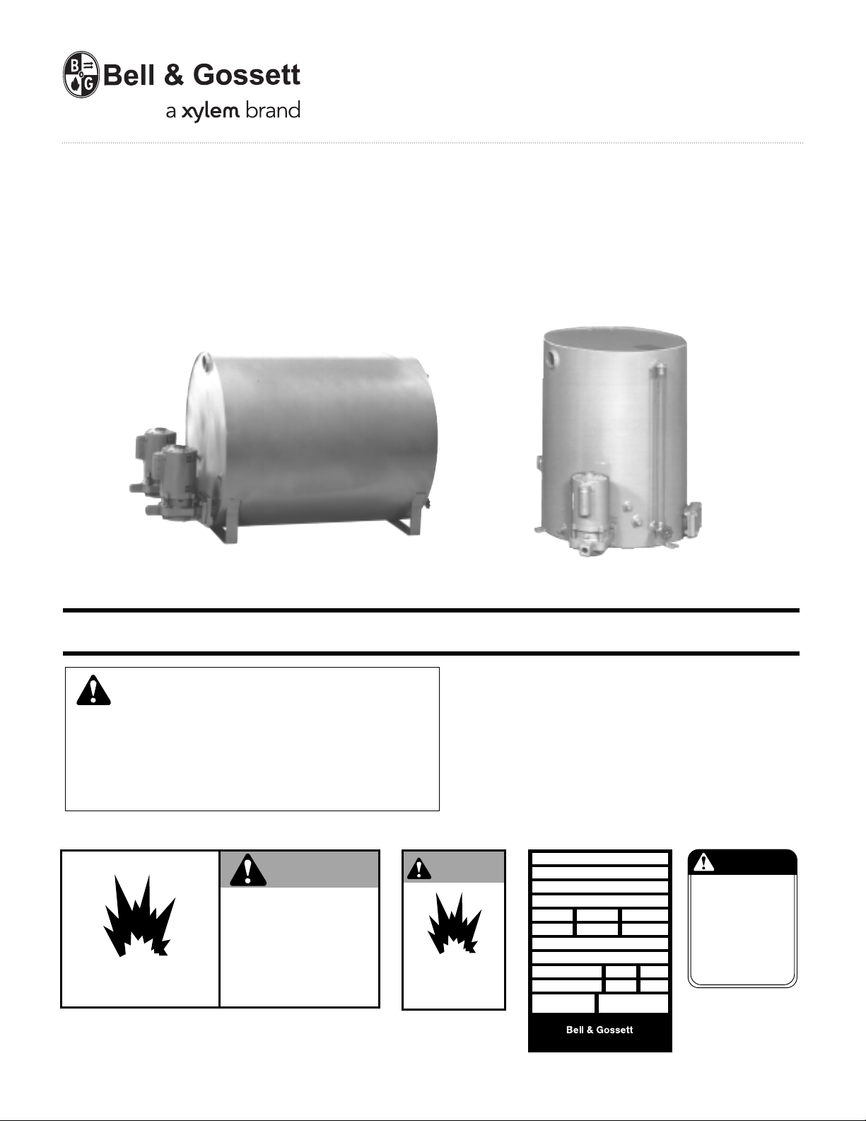
Vented Boiler Feed Units
Series HBF and VBF
Series HBF Model 50VBF-D
Duplex, 50 gallon receiver
Series VBF, Model 50VBF-S
Simplex, 50 gallon receiver
INSTALLER: PLEASE LEAVE THIS MANUAL FOR THE OWNER’S USE.
SAFETY
INSTRUCTIONS
This safety alert symbol will be used in this manual and on
the unit safety instruction decals to draw attention to safety
related instructions. When used, the safety alert symbol
means ATTENTION! BECOME ALERT! YOUR SAFETY IS
INVOLVED! FAILURE TO FOLLOW THESE INSTRUCTIONS
MAY RESULT IN A SAFETY HAZARD.
DO NOT PRESSURIZE TANK.
ISOLATE TANK DURING LEAK TEST.
DO NOT RESTRICT VENT.
DO NOT PLUG OVERFLOW.
OPEN INLET VALVES SLOWLY.
DO NOT USE AS A FLASH TANK.
FAILURE TO FOLLOW
EXPLOSIBLE
(2) All Units
DN0483 (Small) - DN0484 (Large)
INSTRUCTIONS COULD RESULT
IN SERIOUS INJURY OR DEATH.
DURING LEAK TEST
If the decals as noted below are missing or are illegible contact your local B&G representative for a replacement.
1. Electrical connections to be made by qualified Electrician in
accordance with all National, State and Local codes.
2. If pump, motor or piping are operating at extremely high or
low temperatures, guarding or insulation is required.
3. Operating personnel should be trained in the operation of
pumps and associated systems (condensate, boiler feed
units).
®
DO NOT RUN PUMP DRY,
SEAL DAMAGE MAY OCCUR.
INSPECT PUMP SEAL
REGULARLY FOR LEAKS,
REPLACE AS REQUIRED.
FOR LUBRICATION
REQUIREMENTS, CONSULT
SERVICE INSTRUCTIONS.
FAILURE TO FOLLOW
INSTRUCTIONS COULD
RESULT IN INJURY OR
PROPERTY DAMAGE.
P70644 All Units
WARNING
EXPLOSIBLE
ISOLATE TANK
(2) All Units
DN0485 (Small)
DN0486 (Large)
HOFFMAN SPECIALTY
SERIES HV
MODEL
SERIAL
GPM PSI PUMP
CFM IN HG. PUMP
DWGS
POWER V. PH. HZ 60
CONTROL V. PH. 1 HZ 60
TOTAL LARGEST MOTOR
F.L. AMP F.L. AMP
DN0016
DN0116 Units with Panel
TM
Morton Grove, Illinois 60053
CAUTION
P70644
Page 2
DESCRIPTION
Boiler feed units are designed to pump water into an operating
boiler. The pumps are controlled by level controls on the boiler.
Boiler feed units are normally sized to accommodate system
surges and also to provide for the addition of fresh water as
required.
Series VBF and HBF units are standardized feed units intended
for application to low pressure boilers. Pump discharge pressures are 20 psi (1.4 bar), 25 psi (1.7 bar) and 30 psi (2 bar) depending upon model specified. Receivers are heavy gauge, noncode steel. HBF receivers are provided with the Hoffguard™
corrosion resistant coating for longer life.
Receivers are non-code steel.
PRELIMINARY INSPECTION
Assure that there is no shipping damage.
Assure that nameplate ratings agree with job specifications
and actual conditions.
Remove all plastic shipping plugs from receiver and pumps.
HANDLING
Use care in installing unit.
LOCATION
Place unit for easy access to all parts. Allow adequate space
for servicing. Check ambient conditions.
NOTICE / TEMPERATURE LIMITS
Motors are designed to operate in 104˚F (40˚C) max. ambient.
Insulate or ventilate as required.
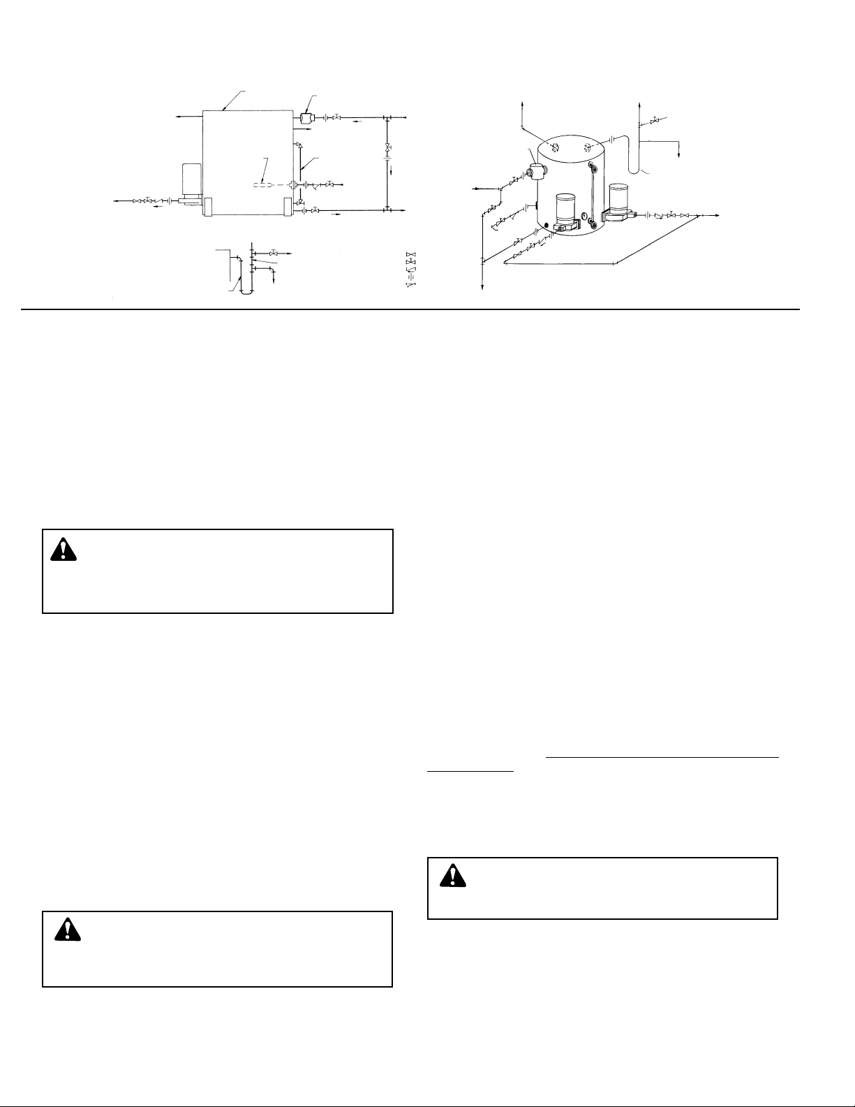
PIPING (General)
Pipe the unit per the above Piping Diagram. Locate and support piping so as to not load the pump discharge.
PIPING (Returns)
Gravity return lines from system must be properly pitched
down to unit inlet. Returns must also be trapped to prevent steam entry into the unit. An inlet basket strainer is
recommended.
PIPING (Vent)
Install a vent pipe to atmosphere. Pipe to be size of vent port
on unit. Do not restrict or reduce vent opening or exceed 20
feet vertical height unless an overflow connection is provided.
PIPING (Overflow)
Pipe overflow connection to drain. When condensate temperature exceeds 200˚F (93˚C) an overflow loop must be used.
PIPING (PUMP DISCHARGE)
Connect the pump discharge(s) to the boiler in accordance
with the above diagram. This piping must be coordinated with
electrical controls in the case of multiple pumps and multiple
boilers.
Boiler feed systems are supplied to meet a wide variety of system specifications. The electrical controls and piping systems
must be coordinated.
WATER MAKE-UP
A mechanical valve is furnished for water make-up. A “Y”
strainer is recommended ahead of this valve. See page 5 for
detailed information. The inlet water pressure must not exceed
30 psi (2.0 bar).
ELECTRICAL WIRING & CONTROLS
Connect power wiring per National Electrical Code. Recheck
nameplate vs. specifications and conditions. All single phase
motors have internal thermal protection.
All series VBF units are furnished with 115/230V 1 Phase,
60Hz motors. Factory motor wiring is for 115V. To convert
motor to 230 volt, follow motor manufacturers instructions.
CAUTION / NOT A CHEMICAL PUMP: Inject boiler
feed compounds from chemical feed tank into boiler
feed piping — never into boiler feed tank. Failure to follow these instructions could result in injury or property
damage.
WARNING / HIGH VOLTAGE ELECTRICITY: Dis-
connect and lock out power before connecting or
servicing unit. Failure to follow these instructions could
result in serious injury or death.
INSTALLATION AND DESCRIPTION (TYPICAL PIPING DIAGRAM)
WARNING: EXPLOSIBLE
Do not pressurize receiver. Isolate receiver during
leak test. Do not plug overflow. Do not restrict vent opening
to atmosphere. Open valves slowly. Failure to follow these
instructions could result in serious injury or death.
2
Pump
Discharge
SERIES VBF
SERIES HBF
Full Size Air Vent
To Atmosphere
Boiler Feed
Receiver
Basket Strainer
Overflow
(See Detail)
Condensate Return
From System
Gauge
Glass
Make-Up
Water
Supply
(See Note 1)
NOTE:
1. Inlet water pressure
should not exceed 30
psi (2.0 bar). For water
systems in excess of 30
psi (2.0 bar), use a Bell
& Gossett #6 Pressure
Reducing Valve, set at
30 psi (2.0 bar).
Boiler
Feed Pump
Receiver
Overflow Loop
To Drain
Vent
OVERFLOW LOOP DETAIL
Loop Fill
Syphon Breaker
Vent To Atmosphere
Vent
Loop Fill
To Drain
Overflow Loop
To Drain
Water
Make-Up
Inlet Strainer
Plug Cock
Gate Valve
Check Valve
Union
Y-Strainer
Return From
System
Mechanical
Make-Up Valve
To
Drain
Page 3
3
PUTTING THE UNIT INTO SERVICE
1. Assure that the unit is piped in accordance with instructions on page 2.
2. Isolate tank before performing any system leak test. Do
not pressurize the tank as part of the leak test. Failure to
do this can result in serious injury or death.
3. Check power leads in accordance with wiring diagram (by
others).
4. Install drain plugs.
5. Fill receiver half full of water to prime pump(s) and prevent
possible damage to pump seals. Avoid freezing conditions
after unit receiver has been filled.
6. Throttle plug cock in discharge line until pressure at pump
(while pump is discharging) approaches pump rated pressure. Tighten plug nut to secure adjustment.
7. Connect the water make-up assembly to city water. Use
piping as least as large as the valve piping provided. A
manual fill valve is also recommended. If city water pressure exceeds 30 psi (2.0 bar), install pressure reducing
valve.
8. Boiler Level Controls — Assure that the controls on and
related to the boiler match the control systems provided
on the unit.
9. Check that the pump discharge pressure exceeds the
maximum operating pressure of the boiler.
10. Assure that the make-up valve admits water.
11. If possible, observe operation thru several cycles.
OPERATION AND MAINTENANCE
Operators must be familiar with all sections of this manual to
understand the operation of the unit.
Hot water, steam and electricity can be hazardous.
Check motor nameplate for any lubrication requirements.
Pumps require no lubrication.
NOTICE / AUTO RESTART
Single phase motors will restart automatically after thermal
overload protector trips.
A properly installed unit should function unattended for long
periods of time. Periodic checks to assure proper operation
are highly recommended. Refer to trouble shooting section
when necessary.
The inlet strainer (when furnished) is intended to protect the
pump and system. Periodic cleaning should be included in the
maintenance schedule. Check frequently in new systems.
WARNING / HIGH VOLTAGE: Disconnect and lock
out power before connecting or servicing unit.
Failure to follow these instructions could result in serious
injury or death.
WARNING / MAINTAIN BOILER SAFETY FEATURES:
When connecting the boiler feed unit to the
boiler, assure that all boiler safety controls (burner cutoff,
etc.) are and remain operational. With certain control
arrangements, dedicated boiler controllers are required
for the boiler feed pumps. Failure to follow these instructions could result in serious injury, death or extensive
property damage.
CAUTION / DO NOT RUN DRY. SEAL DAMAGE
MAY OCCUR:
Inspect pump seal regularly for
leaks. Replace as required. Failure to follow these
instructions could result in serious injury, death or extensive property damage.
WARNING / HIGH VOLTAGE: Disconnect and lock
out power before connecting or servicing unit.
Failure to follow these instructions could result in serious
injury or death.
WARNING / EXPLOSIBLE: The installed boiler feed
unit becomes an integral part of the boiler system.
Boiler operation and maintenance requires specific skills
and training and may require licensing or certification.
The boiler feed unit must be operated and maintained so
as not to jeopardize the boiler operation. Failure to follow
these instructions could result in serious injury, death or
extensive property damage.
SAFETY INSTRUCTIONS: SEE COVER OF THIS
MANUAL.
CAUTION / SUBSEQUENT DAMAGE: A unit show
ing symptoms of possible problems (overflow,
noise, leaks, vibrations, continual operation, etc.) must be
corrected immediately. Failure to follow this instruction
may result in full liability for subsequent injury or property
damage.
WARNING: EXPLOSIBLE
Do not pressurize receiver. Isolate receiver during
leak test. Do not plug overflow. Do not restrict vent opening
to atmosphere. Open valves slowly. Failure to follow these
instructions could result in serious injury or death.
WARNING: EXPLOSIBLE
Do not pressurize receiver. Isolate receiver during
leak test. Do not plug overflow. Do not restrict vent opening
to atmosphere. Open valves slowly. Failure to follow these
instructions could result in serious injury or death.
Page 4

4
TROUBLE SHOOTING PROCEDURES
All units are thoroughly tested at the factory before shipment.
They should operate satisfactorily without further adjustment if
properly installed and provided they have not been damaged
by rough handling in transit. If system or unit performance is
not satisfactory, refer to the following check list.
Pump Will Not Start
1. The power supply has been interrupted, disconnect switch
is open or selector switch is improperly positioned.
2. Incorrect voltage for motor. Check voltage and wiring with
motor characteristics.
3. Incorrect starter coil for power supply.
4. The overload relays and the starter have tripped out and
must be reset. Ambient temperature may be too high.
5. Check pump controls or other controls for proper operation.
6. Wiring to control cabinet is incorrect or connections are loose.
7. The basket strainer is dirty thus restricting flow into the
receiver. Clean periodically.
8. Boiler is full or boiler control switch is defective.
Pumps Runs Continuously
1. Steam traps are blowing through causing condensate to return at excessive temperatures. This may reduce the capacity
of pump below its rating. Traps should be repaired or replaced.
2. Pump discharge pressure is less than operating pressure of
the boiler.
3. The total required pressure at the pump discharge is greater
than the pressure for which the pump was designed. Check
the total pressure which includes atmospheric pressure, the
friction head and the static head.
4. A valve in the discharge line is closed or throttled too tightly.
5. Check valve is installed backwards.
6. The impeller eye is clogged.
7. Pump is too small for system.
8. Pump is running backwards.
Boiler Feed Pump is Noisy
1. The pump is working against a lower pressure than
designed for. While pump is discharging, adjust plug cock
in discharge line until pressure at pump approaches pump
rated pressure.
2. Excessive condensate temperature. Correct system conditions.
3. Magnetic hum or bearing noise in motor. Consult motor
manufacturer's authorized serviced station nearest unit
location.
4. Starter chatters. Trouble is caused by low line voltage, poor
connections, defective starter coil, or burned contacts.
5. Pump is running backward.
The System is Noisy
1. Banging in the steam mains is usually caused by steam
passing by condensate that has collected in low lying points
in the line. These problems can be eliminated by dripping
low points, properly supporting the pipe, or by increasing
the pitch of the lines.
2. Improper dripping of the steam mains and risers; where
there is a rise in the steam main, or where it branches off
into a riser, a drip trap must be installed in the drain line.
3. The piping is too small to drain properly.
4. A defective steam trap is holding condensate in steam supply line.
5. Defective check valve permits steam, to vent thru pump into
the boiler feed tank.
6. A priming boiler is discharging water with the steam. Consult boiler manufacturer.
Excessive Water Overflow From Unit
1. Receiver sized too small to accommodate system surges.
2. Water make-up valve open or float set too high.
3. Water make-up valve leaks.
4. Supply water pressure exceeds 30 psi (2.0 bar). Install
Pressure Reducing Valve.
Bell & Gossett
Morton Grove, IL, U.S.A.
DEALER SERVICING
If trouble occurs that cannot be rectified, contact your local
B&G representative. He will need the following information in
order to give you assistance.
1. Complete nameplate data of pump and motor. SEE RATING
NAMEPLATE.
2. Suction and discharge pipe pressure gauge readings.
3. Ampere draw of the motor.
4. A sketch of the pump hook-up and piping.
5. Provide complete information on boiler control switches and
any motorized or solenoid valves in the boiler feed piping.
HOFFMAN SPECIALTY
SERIES
MODEL
SERIAL
GPM PSI PUMP
CFM IN. HG. PUMP
DWGS
POWER V
CONTROL V. PH. 1 HZ 60
TOTAL
F.L. AMP.
DN0016
.
115
PH. HZ 60
LARGEST MOTOR
F.L. AMP.
®
Page 5

5
MAKE-UP WATER VALVE
INSTRUCTIONS
Item No. Part
Number Description Req’d. No.
1, 2, 3 & 4 Float Valve Assembly 1 DL1634
3 Float 1 DA0164
2 & 4 Float Valve Only 1 DV1024
(Less float and
adapter)
1 Adapter 1 DL1750
Adjustment — The make-up water valve is factory set to main-
tain receiver water level at approximately
1
/2 full. When systems
require a large percentage of make up water, the float setting
should be raised to utilize full receiver capacity. When large percentages of returns from the system are available the float setting
may be lowered to not less than 4" (101 mm) above the top of the
pump suction opening.
A float arm pivot allows the float setting to be raised or lowered.
The valve must be removed to change float setting. This adjustment can be accomplished by loosening the screw on the float
arm pivot and setting the arm position to the level desired. When
the desired setting is attained interlock the toothed pivot and
tighten the screw to secure the setting. Reinstall valve in the
receiver.
Maintenance — The “Y” strainer should be cleaned periodically.
During the first few weeks of operation the strainer screen should
be checked and cleaned every week. The screen can be removed
for cleaning through the strainer’s branch connection. The valve
should be observed for tight closing and proper level on a periodical basis.
Pressure Limitation — Inlet water pressure to the make up valve
should not exceed 30 psi (2.0 bar). For water systems in excess
of 30 psi (2.0 bar), installation of a Bell & Gossett #6 pressure
reducing valve to reduce make up water pressure below 30 psi
(2.0 bar) is recommended.
Mounting — The valve is mounted on a 21/2" (64 mm) NPT pipe
plug located on the side of the receiver. The entire assembly may
be removed through the tapped opening. The “B” stamped on
the valve mounting bushing should always be at the bottom of
the installed plug to assure proper alignment.
Make-up Water Valve
This unit is equipped with an internal water make-up
valve pre-set at the factory.
The valve may be readjusted to add make-up water at
other water levels. Remove assembly to readjust level.
NOTICE: PRESSURE LIMITATION.
Inlet water pressure should not exceed 30 psi. For water
systems in excess of 30 psi use a Bell & Gossett #6
Pressure Reducing Valve adjusted to 30 psi.
NOTICE: ALIGNMENT REQUIRED.
The “B” stamped on the valve mounting bushing should
always be at the bottom of the installed valve.
MAKE-UP WATER CONNECTION
NOTE:
INSTALL “B” (BOTTOM)
IN LINE WITH
WATER DISCHARGE
IDL001
DN0122
DSK-978 Fig. 2
STAMP “B”
WATER
DISCHARGE
Page 6

6
These close coupled vertical centrifugal pumps are equipped
with mechanical seals. If system has not been properly
cleaned prior to installation of pump, foreign matter such as
dirt, pipe scale, core sand, etc. may clog the impeller and
damage the seal. A strainer is recommended in return line to
pump.
Pump must not be operated dry. Seals may be dam-
aged if operated without water present.
1. Close inlet line gate valve and operate pump momentarily
to remove as much liquid as possible from pump. Close
discharge line gate valve.
2. Shut-off and lock-out power.
3. Disconnect wiring to motor.
4. Make sure unit is cool enough that pump can be handled
safely. Open receiver drain to remove remaining liquid.
5. Loosen the four capscrews (4) holding pump case to
motor. Assure that pressure is relieved per caution note.
6. Remove four capscrews (4) holding pump case to motor
and lift motor and impeller out of pump case.
7. Remove pump/motor assembly and place on work bench.
8. Prevent the motor shaft from turning by inserting a large
screwdriver into the screwdriver slot located under the
plug on the rear motor endbell. Back the impeller off
(counter clockwise) using a rectangular bar or other flat
tool inserted between the impeller vanes.
9. Remove the rotating part of the mechanical seal from the
end of the shaft.
10. Remove seal holder (13) with stationary ceramic part of
mechanical seal and cup rubber from the end of the shaft.
11. Remove stationary ceramic part of mechanical seal and
cup rubber from recess in seal holder.
12. To install new seal, proceed as follows: Clean recess in
seal holder thoroughly. Insert new ceramic seat (grooved
face first) into the rubber seat cup. Lubricate the outside of
the cup and seal holder recess with soapy water. Install
the ceramic/cup assembly into the seal holder, making
sure the assembly bottoms evenly. When repairing "B"
style pumps manufactured between 1983 through 2001,
orient wire spacer eye to the left midway between motor
lugs. Replace seal holder over wire spacer on the face of
the motor, maintaining concentricity with motor face.
Pumps manufactured in 2002 or later, are manufactured
with DP1966 seal holder and do not require the wire
spacer. Pumps using DP1966 should orient the seal holder
tab to the left, midway between motor lugs. Using a clean,
lint-free cloth, wipe the mating surfaces of the seal clean
of any foreign matter. Moisten the carbon section of the
rotating part of the seal and lubricate the I.D. with soapy
water. Place onto shaft to seat against the ceramic.
13. Hold motor shaft as described in #8 and replace the impeller on the shaft (clockwise rotation) making sure it is tight.
14. Orient motor for pump reassembly with conduit opening to
the left. When mounting the pump case, discharge should
be 90˚ to the right of the wire spacer eye or (90˚ to the tabs
on DP1966) and conduit opening on motor. Use care to
insure tight gasket fit to prevent water leakage. When
replacing pump case, the wire spacer eye or the tabs on
DP1966 should seat in pump case notch. If this does not
occur inspect for proper alignment and reassemble.
15. Replace four capscrews (4). Tighten down capscrews
evenly to avoid damage.
16. Reconnect pump bleed line (where applicable) and motor
wiring.
PUMP SERVICE INSTRUCTIONS FOR WATCHMAN CENTRIFUGAL PUMPS
WARNING / HIGH VOLTAGE: Disconnect and lock
out power before connecting or servicing unit.
Failure to follow these instructions could result in serious
injury or death.
CAUTION / HOT SURFACES: Surfaces are hot
when system is in operation. Do not touch hot receiver, let unit cool before servicing. Failure to follow
these instructions could result in injury or property damage.
CAUTION / PRESSURIZED SYSTEM: Operating
system may contain very hot water under pressure.
Close inlet and open drains before servicing. When servicing,
loosen screws and move components to assure
pressure is relieved before
removing screws. Keep drains
open during servicing. Failure to follow these instructions
could result in injury or property damage.
Item No. Part
Number Description Req'd. No.
1 Motor 1/3 hp, 1 ph. 3500 rpm 1 180096
2 Seal Holder 1 DP1966
3 Seal* 1 —
4 Impeller 1 DP0321
5 Head Gasket* 1 DG0092
6 Pump Case with
wearing ring 1 DP1665
7 Capscrew 1 DJ0083
8 Wear Ring 1 DP0482
9 Pipe Plug 1/4" (6 mm) 1 P39040
10 Water Slinger 1 DP0848
Seal kit including
mechanical seal, head
* gasket, & case to
receiver gasket 1 180013
Complete pump and
motor assembly 1 180001
Order Replacement Parts by Description and Part No.
Specify Serial No. shown on nameplate.
1
2
5
9
6
8
10
7
3
4
Page 7

7
17. Close drain and slowly open inlet valves. See warning.
18. Jog to check motor rotation. See caution.
19. Observe operation thru several cycles.
Close coupled centrifugal pumps are designed for years of
trouble free service. Units have mechanical shaft seals.
1. Close inlet line gate valve and operate pump momentarily
to remove as much liquid as possible from pump. Close
discharge line gate valve.
2. Shut-off and lock out power.
3. Make sure unit is cool enough that pump can be handled
safely. Open drain to remove remaining liquid.
4. Carefully remove pump drain plug and bleed line. Wait for
complete drainage.
5. Loosen the motor bracket to pump volute capscrews.
Assure that pressure is relieved per caution note.
6. Complete the removal of the above hardware. Remove
pump/motor assembly and place on work bench.
7. Remove self locking stainless steel capscrews and stainless steel washer (or self locking brass cap nut and washer)
that secure the impeller in place.
8. To remove impeller from motor shaft proceed as follows:
(1) Keyed Shafts. Remove impeller with gear puller or
other means which will not damage impeller or bend
motor shaft.
(2) Threaded Shafts. Hold end of motor shaft opposite
pump with large screwdriver or other suitable tool and
back impeller with a rectangular bar or other flat tool
inserted between the vanes of the impeller.
9. Remove rotating part of seal from shaft, being careful not
to break carbon face.
10. Remove capscrews holding motor bracket to motor and
remove bracket.
11. Remove stationary part of seal assembly, being careful not
to chip or break ceramic seal.
12. To install new seal proceed as follows:
(1) Clean recess in bracket thoroughly. Coat recess and
“rubber” portion of seat with soap solution. Press seat
into recess firmly by hand making certain both parts
bottom evenly. If seal cannot be bottomed with fingers
place cardboard shipping disc on ceramic and force
into place with flat tool.
(2) Carefully place bracket in position on motor shaft with
out displacing ceramic seat and secure bracket to
motor with capscrews.
(3) Place motor vertically with pump end up. Do not
attempt assembly of seal and impeller with shaft
horizontal.
PUMP SERVICE INSTRUCTIONS FOR CENTRIFUGAL PUMPS
Vertical mounting puts motor above floor dirt and water
CAUTION / DO NOT RUN DRY. SEAL DAMAGE
MAY OCCUR:
Inspect pump seal regularly for
leaks. Replace as required. Failure to follow these
instructions could result in injury or property damage.
WARNING / HIGH VOLTAGE: Disconnect and lock
out power before connecting or servicing unit.
Failure to follow these instructions could result in serious
injury or death.
CAUTION / HOT SURFACES: Surfaces are hot
when system is in operation. Do not touch hot receiver, let unit cool before servicing. Failure to follow
these instructions could result in injury or property damage.
CAUTION / PRESSURIZED SYSTEM: Operating
system may contain very hot water under pressure.
Close inlet and open drains before servicing. When servicing,
loosen screws and move components to assure
pressure is relieved before
removing screws. Keep drains
open during servicing. Failure to follow these instructions
could result in injury or property damage.
CAUTION / DO NOT REVERSE: Reverse operation
can cause extensive damage to pumps. Jog the
motor to test for direction of rotation. Failure to follow
these instructions could result in injury or property damage.
WARNING: EXPLOSIBLE
Do not pressurize receiver. Isolate receiver during
leak test. Do not plug overflow. Do not restrict vent opening
to atmosphere. Open valves slowly. Failure to follow these
instructions could result in serious injury or death.
Page 8

Item No. Part
Number Description Req’d. No.
1 Motor — Order by Description 1 Consult Factory
2 Impeller 1 Consult Factory
3 Pump Head 1 DP0208
4 Case with Wear Ring 1 DP1603
5 Wearing Ring 1 DP0482
8 Impeller Capscrew 1 DJ0213
9 Impeller Washer 1 DJ0267
10 Capscrews 8 DJ0066
18 Water Slinger 1 DP0848
Seal Kit Including Mech
6,7
Seal, Head Gasket
Complete Pump and
Motor Assembly
Case to Rec. Gasket 1 DG0060
Order Replacement Parts by Description and Part No.
Specify Serial No. shown on nameplate.
1 180014
1 Consult Factory
(4) The carbon ring of the rotating seal part should not be
loose in the seal head. If it is, apply a small amount of
grease to the rubber bellows underneath the carbon
ring to hold the ring in place. Using clean, lint free
cloth, wipe mating surfaces perfectly clean. Soap shaft
and push seal onto shaft so that carbon will contact
ceramic seal. If spacer is required, use grease to cause
spacer to adhere to bottom of seal after seal has been
put on shaft. Be sure spacer is on larger diameter of
shaft so that it will not catch between shoulder and
impeller.
13. Replace impeller on shaft. Replace stainless steel washer
and secure impeller with capscrew or cap nut.
14. Place new gasket on pump volute and reassemble motor
and pump subassembly on pump volute.
15. Reconnect pump bleed line and motor wiring.
CAUTION / DO NOT RUN DRY. SEAL DAMAGE
MAY OCCUR: Inspect pump seal regularly for
leaks. Replace as required. Failure to follow these
instructions could result in injury or property damage.
16. Close drain and slowly open inlet valves. See warning.
WARNING: EXPLOSIBLE
Do not pressurize receiver. Isolate receiver during
leak test. Do not plug overflow. Do not restrict vent opening
to atmosphere. Open valves slowly. Failure to follow these
instructions could result in serious injury or death.
17. Jog to check motor rotation. See caution.
CAUTION / DO NOT REVERSE: Reverse operation
can cause extensive damage to pumps. Jog the
motor to test for direction of rotation. Failure to follow
these instructions could result in injury or property damage.
18. Observe operation thru several cycles.
Xylem Inc.
8200 N. Austin Avenue
Morton Grove, Illinois 60053
Phone: (847) 966-3700
Fax: (847) 965-8379
www.xyleminc.com/brands/bellgossett
Bell & Gossett is a trademark of Xylem Inc. or one of its subsidiaries.
© 2012 Xylem Inc. DN0162F November 2012
 Loading...