

Page 1
INSTRUCTION MANUAL
WARNING
DN0147
REVISION D
Hoffman Specialty
®
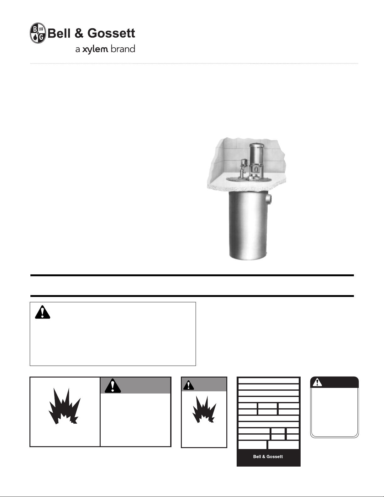
Underground Condensate
and Boiler Feed Units
Series UH, UHM
INSTALLER: PLEASE LEAVE THIS MANUAL FOR THE OWNER’S USE.
SAFETY
INSTRUCTIONS
This safety alert symbol will be used in this manual and on
the unit safety instruction decals to draw attention to safety
related instructions. When used, the safety alert symbol
means ATTENTION! BECOME ALERT! YOUR SAFETY IS
INVOLVED! FAILURE TO FOLLOW THESE INSTRUCTIONS
MAY RESULT IN A SAFETY HAZARD.
DO NOT PRESSURIZE TANK.
ISOLATE TANK DURING LEAK TEST.
DO NOT RESTRICT VENT.
DO NOT PLUG OVERFLOW.
OPEN INLET VALVES SLOWLY.
DO NOT USE AS A FLASH TANK.
FAILURE TO FOLLOW
EXPLOSIBLE
(2) All Units
DN0483 (Small) - DN0484 (Large)
INSTRUCTIONS COULD RESULT
IN SERIOUS INJURY OR DEATH.
If the decals as noted below are missing or are illegible con-
tact your local B&G representative for a replacement.
1. Electrical connections to be made by qualified Electrician in
accordance with all National, State and Local codes.
2. Motor must have properly sized starter with properly sized
heaters to provide overload and undervoltage protection.
3. If pump, motor or piping are operating at extremely high or
low temperatures, guarding or insulation is required.
4. Operating personnel should be trained in the operation of
Condensate and/or Boiler Feed Units.
WARNING
EXPLOSIBLE
ISOLATE TANK
DURING LEAK TEST
(2) All Units
DN0485 (Small)
DN0486 (Large)
HOFFMAN SPECIALTY
SERIES UH
MODEL
SERIAL
GPM PSI PUMP
CFM IN HG. PUMP
DWGS
POWER V. PH. HZ 60
CONTROL V. PH. 1 HZ 60
TOTAL LARGEST MOTOR
F.L. AMP F.L. AMP
DN0016
DN0116 Units with Panel
TM
Morton Grove, Illinois 60053
®
CAUTION
DO NOT RUN PUMP DRY,
SEAL DAMAGE MAY OCCUR.
INSPECT PUMP SEAL
REGULARLY FOR LEAKS,
REPLACE AS REQUIRED.
FOR LUBRICATION
REQUIREMENTS, CONSULT
SERVICE INSTRUCTIONS.
FAILURE TO FOLLOW
INSTRUCTIONS COULD
RESULT IN INJURY OR
PROPERTY DAMAGE.
P70644 All Units
P70644
Page 2
2
DESCRIPTION
Series UH condensate units have one (simplex) or two (duplex)
pumps which are controlled by float(s) switch or mechanical
alternator switch in the receiver.
These pump return accumulated condensate to the boiler feed
system.
Series UHM boiler feed units have one (simplex) or two
(duplex) pumps which are controlled by boiler system controllers. Series UHM receivers are sized to provide for accumulating system surges of condensate. Water makeup valves
are also included to insure that water is always available to
meet boiler demands.
Receivers are non-code cast iron.
PRELIMINARY INSPECTION
Assure that there is no shipping damage.
Assure that nameplate ratings agree with job specifications
and actual conditions.
HANDLING
Use care in installing unit.
LOCATION
Place unit for easy access to all parts. Allow adequate space
for servicing. Check ambient conditions.
NOTICE / TEMPERATURE LIMITS
Motors are designed to operate in 104ºF max. ambient.
Insulate or ventilate as required.
PIPING (General)
Pipe the unit per the Elementary Piping Diagram. Locate and
support piping so as not to load the pump discharge.
PIPING (Returns)
Gravity return lines from the system must be properly pitched
down to unit inlet. Returns must also be trapped to prevent
steam entry into the unit. An inlet basket strainer is recommended.
PIPING (Vent)
Install a vent pipe to atmosphere. Pipe to be size of vent port
on unit. Do not restrict or reduce vent opening or exceed 20
inch vertical height unless an overflow connection is provided.
FLOAT SWITCHES AND MECHANICAL ALTERNATORS
The floats which operate these switches are factory set but
can be field readjusted as required.
Adjustment is made by removing the float switch as an
assembly and readjusting the stop collars on the float rod.
Setting should utilize as much of the tank volume as practical.
Settings should avoid “short cycling” of the pump. See page 3
for detailed instructions.
ELECTRICAL WIRING & CONTROLS
Connect power wiring per NEC. Recheck nameplate vs. speci-
fications and conditions. All single phase motors have internal
thermal protection.
Three phase motors must use starters with properly sized
overload relays. Overload relays furnished are designed for
manual reset.
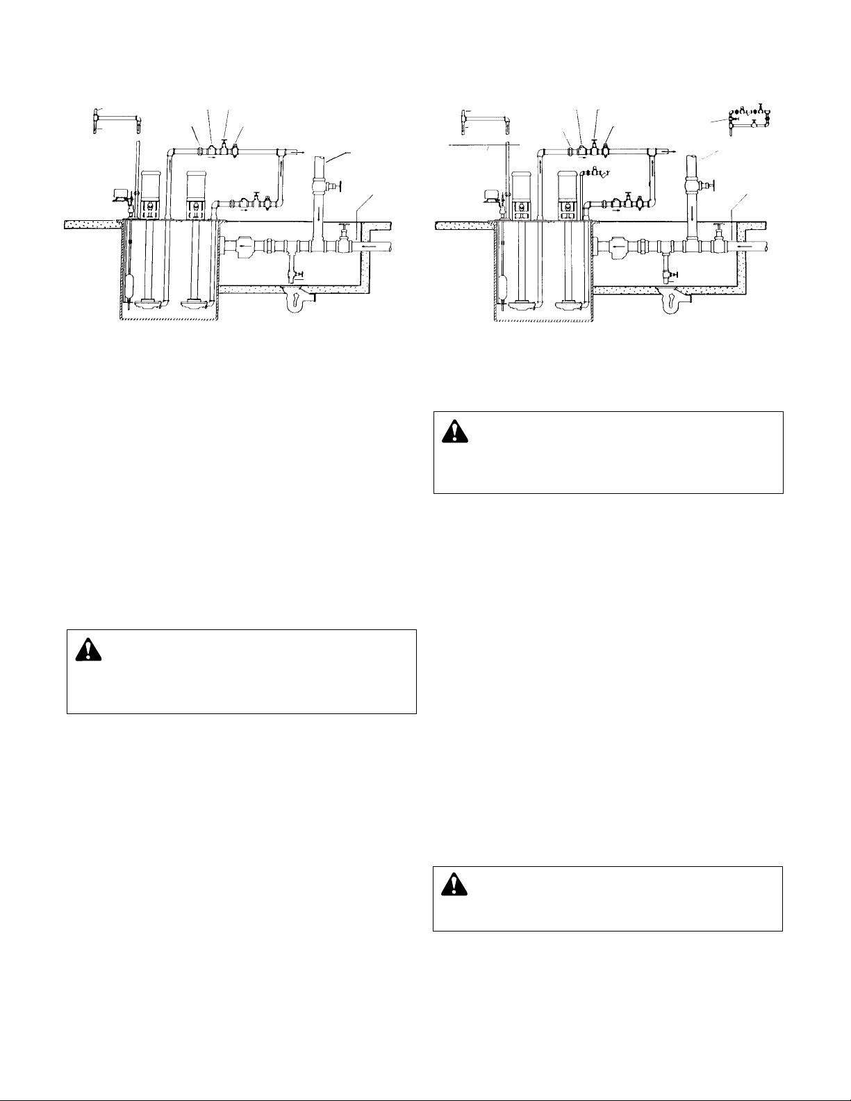
SERIES UH – CONDENSATE UNIT
REPRESENTATIVE PIPING DIAGRAMS
AIR VENT
TO DRAIN
UNION
CHECK VALVE
GATE VALVE
STEAM COCK
DISCHARGE
CONDENSATE
RETURN LINE
UNDERGROUND
CONDENSATE
RETURN LINE
BASKET
STRAINER
(OPTIONAL)
UNION
TO DRAIN
IDPD33
AIR VENT
TO DRAIN
WATER LINE
OF BOILER
UNION
CHECK VALVE
GATE VALVE
STEAM COCK
WATER MAKE-UP
WITH 3 VALVE BYPASS
OPTIONAL
DISCHARGE TO BOILER
DETAIL AA
WATER
MAKE-UP
SUPPLY
(SEE DETAIL AA)
CONDENSATE
RETURN LINE
UNDERGROUND
CONDENSATE
RETURN LINE
BASKET
STRAINER
UNION
TO DRAIN
IDPD44
SERIES UHM BOILER FEED UNIT
WARNING: EXPLOSIBLE
Do not pressurize receiver. Isolate receiver during
leak test. Do not plug overflow. Do not restrict vent opening
to atmosphere. Open valves slowly. Failure to follow these
instructions could result in serious injury or death.
CAUTION: NOT A CHEMICAL PUMP
Inject boiler feed compounds from chemical feed
tank into boiler feed piping – never into condensate tank.
Failure to follow these instructions could result in injury or
property damage.
WARNING: HIGH VOLTAGE ELECTRICITY
Disconnect and lock out power before connecting or
servicing unit. Failure to follow these instructions could
result in serious injury or death.
Page 3
OPEN VENT
TO DRAIN
WATER MAKE-UP
SUPPLY
GV
Y STRAINER
SOLENOID VALVE
CV
DISPLACER SWITCH TO
ACTUATE VACUUM PUMP
FOR OVERFLOW CONTROL
BASKET STRAINER
RETURN LINE
GV
GV
GV
U
U
U
U
CV
PC
VACUUM TIGHT UNDERGROUND BOILER FEED UNIT TYPE CMVU
CV
PUMP MOTOR ACTUATED BY
BOILER WATER LEVEL CONTROLLER
THERMOSTATIC TRAP OPTIONAL
GV
EQUALIZING LINE
TO BOILER
AIR AND EXCESS WATER
SUCTION LINE TO
VACUUM PUMP
PUMP DISCHARGE
IDPD55
PUMP DISCHARGE
IDPD54
AIR SUCTION LINE
TO VACUUM PUMP
EQUALIZING LINE
TO SUPPLY SIDE
OF SYSTEM
PCGVGV
CV
U
THERMOSTATIC TRAP OPTIONAL
PUMP MOTOR ACTUATED BY
FLOAT SWITCHES
CV
GV
U
CV
DISPLACER SWITCH
TO ACTUATE PUMP
BASKET
STRAINER
GV
OPEN VENT
TO DRAIN
RETURN LINE
VACUUM TIGHT UNDERGROUND CONDENSATION PUMP TYPE CVU
LEGEND
CV - CHECK VALVE
GV - GATE VALVE
PC - PLUG LOCK
U - UNION
3
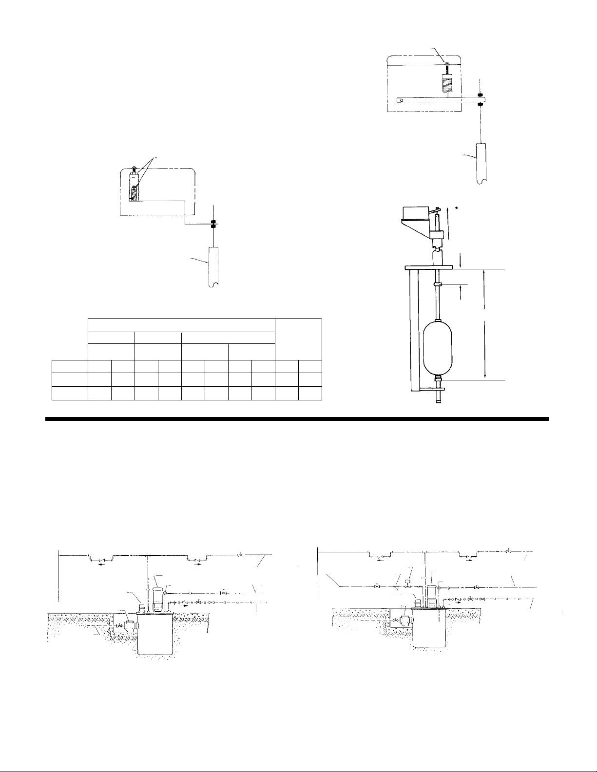
FLOAT SWITCH ADJUSTMENT
The float positions are factory set. These positions should be
reset as necessary. Minor deviation is permissible to meet
local requirements. The settings must avoid “short cycling” of
the pumps.
The float switch and mechanical alternator each have an internal compensating spring to balance the weight of the float
guide rod. These springs are to have just enough tension or
compression on the float switch to counterbalance the guide
(but not the float).
PIPING DIAGRAMS VACUUM TIGHT
UNDERGROUND CONDENSATE &
BOILER FEED UNITS
Type CVU units are designed for use as a mechanical lift in a
vacuum heating system. They are also used to return condensate under vacuum to a boiler feed tank. They have vacuum
tight displacer switch(es) for pump control.
Type CMVU units have water make-up valve and are actuated
by boiler controller. They are designed for use in a vacuum
system to discharge condensate directly to the boiler.
It is necessary to pipe the vent line to atmosphere using full
vent port size piping with check valves installed as shown on
diagrams. It is also recommended that the vent line be
“dripped” to drain to prevent an accumulation of condensate
in the vent pipe.
MECHANICAL
ALTERNATOR
*MAKE SETTINGS
WITH ARM AT
HIGHEST POSITION
FLOAT SWITCH
PIPING DIAGRAM FOR UNDERGROUND
CONDENSATE UNIT USED
IN A VACUUM SYSTEM
PIPING DIAGRAM FOR UNDERGROUND
BOILER FEED UNIT USED
IN A VACUUM SYSTEM
FLOAT SETTING CHART
Condensate Unit
Single Duplex Duplex 2 Float Switch Boiler
Primary Stand-By
Feed
Unit (Mech. Alt.) Float Switch Float Switch Unit
Depth “A”“B”“A”“B”“A”“B”“A”“B”“A”“B”
36" 11" 22" 81/2" 21" 121/2" 22" 11" 22" 14" 22"
48" 11" 34" 81/2" 33" 121/2" 34" 11" 34" 26" 34"
2DFS01
COMPENSATING
SPRING ADJUSTER
FLOAT GUIDE
“A”
“B”
FLOAT GUIDE
COMPENSATING
SPRING ADJUSTERS
IDPD55
Page 4

4
1. Assure that the unit is piped in accordance with instructions
on page 2.
2. Isolate tank before performing any system leak test. Do not
pressurize the tank as part of the leak test. Failure to do this
can result in serious injury or death.
3. Check floats and alternators for free operation.
4. Check power leads in accordance with wiring diagram
enclosed in control cabinet (when furnished).
5. Install drain plugs.
6. Fill receiver half full of water to prime pump(s) and prevent
possible damage to pump seals. Avoid freezing conditions
after unit receiver has been filled.
7. Check for proper rotation of all three phase motors. Rotation
must be clockwise looking down on the motor as indicated by
directional arrow on pump casting. If pump runs backwards,
interchange two wires (3 phase only).
8. Throttle plug cock in discharge line until pressure at pump
(while pump is discharging) approaches pump rated pressure.
Tighten plug nut to secure adjustment.
*9.Connect the water make-up assembly to city water. Use pip-
ing at least as large as the valve piping provided. Provide a
manual fill valve if not included on the unit.
*10.
Boiler Level Controls
Assure that the controls on and related to the boiler match the
control systems provided on the unit (see the wiring diagram
furnished) (applicable when electrical control panel is furnished).
*11.Check that the pump discharge pressure exceeds the maxi-
mum operating pressure of the boiler.
*12.Manually move the make-up water float indicator and assure
that the make-up solenoid admits water.
*13.Manually move the low water cut-off float switch indicator to
check for pump shut-off. (When furnished)
14. Remove start-up label (below) from panel (if applicable) after
complying with instructions.
15. If possible, observe operation thru several cycles.
PUTTING THE UNIT INTO SERVICE (ITEMS MARKED * FOR UHM ONLY)
WARNING: HIGH VOLTAGE
Disconnect and lock out power before connecting or
servicing unit. Failure to follow these instructions could
result in serious injury or death.
WARNING: MAINTAIN BOILER SAFETY FEATURES
When connecting the boiler feed unit to the boiler,
assure that all boiler safety controls (burner cutoff, etc.) are
and remain operational. With certain control arrangements,
dedicated boiler controllers are required for the boiler feed
pumps. Failure to follow these instructions could result in
serious injury, death or extensive property damage.
CAUTION: DO NOT RUN DRY.
SEAL DAMAGE MAY OCCUR.
Inspect pump seal regularly for leaks. Replace as required.
Failure to follow these instructions could result in injury or
property damage.
ELECTRICIAN/INSTALLER/OPERATOR
REMOVE AND DESTROY THIS TAG AFTER —
1. ASSURING THAT ALL PUMPS ROTATE CLOCKWISE PER ARROWS CAST ON VOLUTES. (JOG
PUMP MOMENTARILY TO TEST – INTERCHANGE ANY TWO MOTOR POWER WIRES TO
REVERSE 3PH MOTORS.)
2. ASSURING THAT SHIPPING LOCKS HAVE BEEN REMOVED FROM ALL FLOAT SWITCHES.
WARNING: EXPLOSIBLE
Do not pressurize receiver. Isolate receiver during
leak test. Do not plug overflow. Do not restrict vent opening
to atmosphere. Open valves slowly. Failure to follow these
instructions could result in serious injury or death.
OPERATION AND MAINTENANCE
Operators must be familiar with all sections of this manual to
understand the operation of the unit.
Hot water, steam and electricity can be hazardous.
Check motor nameplate for any lubrication requirements.
LUBRICATION
The only pump bearing requiring lubrication is the ball bearing in
the motor support just below the flexible coupling. It has a reservoir, which is filled with moisture resistant high temperature
grease.
Remove pipe plug in motor support and add approximately 3
ounces of Shell Alvania RL 2 grease (or equivalent) from once a
year (normal) to twice a year for extremely hot conditions. Do not
use ordinary grease.
NOTICE / AUTO RESTART
Single phase motors wil restart automatically after thermal over-
load protector trips.
Overload thermal relays in starters must be reset manually.
A properly installed unit should function unattended for long
periods of time. Peroidic checks to assure proper operation are
highly recommended. Refer to trouble shooting section when
necessary.
A variety of control options are available and are furnished in
accordance with user specifications. Refer to wiring diagrams
(when furnished) to determine control switch settings.
The inlet starter (when furnished) is intended to prrotect the pump
and system. Peroidic cleaning should be included in the maintenance schedule. Check frequently in new systems.
WARNING: HIGH VOLTAGE
Disconnect and lock out power before connecting or
servicing unit. Failure to follow these instructions could
result in serious injury or death.
SAFETY INSTRUCTIONS
SEE COVER OF THIS MANUAL
WARNING: EXPLOSIBLE
Do not pressurize receiver. Isolate receiver during
leak test. Do not plug overflow. Do not restrict vent opening
to atmosphere. Open valves slowly. Failure to follow these
instructions could result in serious injury or death.
CAUTION: SUBSEQUENT DAMAGE
A unit showing symptoms of possible problems
(overflow, noise, leaks, vibrations, continual operation, etc.)
must be corrected immediately. Failure to follow these
instructions may result in full liability for subsequent injury
or property damage.
WARNING: EXPLOSIBLE
The installed boiler feed unit becomes an intergral
part of the boiler feed system. Boiler operation and maintenance requires specific skills and training and may require
licensing or certification. The boiler feed unit must be operated and maintained so as not to jeopardize the boiler
operation. Failure to follow these instructions could result in
serious injury or death.
CAUTION: DO NOT REVERSE
Reverse operation can cause extensive damage to
pumps. Jog the motor to test for direction of rotation. Failure
to follow these instructions could result in injury or property
damage.
Page 5

The mechanical seal can be replaced without pulling the unit or
without removing motor wiring. Follow these instructions.
1. Close inlet gate valve and operate pump momentarily to
remove as much liquid as possible from pump. Close discharge line gate valve.
2. Shut-off and lock out power.
3. Make sure unit is cool enough that pump can be handled
safely.
4. Disconnect motor leads and conduit. If flexible conduit is
used, wiring may not need to be disconnected.
5. Remove motor from motor support (half of the flexible coupling will come away with the motor) and set aside.
6. Remove remaining part of flexible coupling from pump.
7. Remove grease coverplate from bearing support.
8. Remove the snap-ring from above the bearing.
9. Remove the four screws that hold the bearing support in
place.
10. Insert two screws,
3
/8 x 16 at least 11/2" long, into the tapped
holes in the flange around the bottom of the bearing support,
and “jack up” the bearing support by turning both screws
evenly, or by alternating half-turns.
11. With the bearing support freed, remove the stationary part of
the seal, the slinger, and the bearing from the bearing support.
Remove the old gasket, and place the new gasket on the
motor support.
12. Check condition of the bearing, and re-grease if necessary,
with Chevron SRI #2 grease.
13. Remove rotating part of seal from shaft, leaving collar in place
on shaft.
14. Place rotating part of new seal on shaft; soap both the shaft
and the “rubber” portion of seal.
15. Clean the recess in the bearing support where the stationary
part of the seal fits.
16. Soap the “rubber” portion of the stationary part of the seal
and press it and the ceramic seat into the cavity in the bearing
support, being certain both parts are bottomed evenly.
17. Lower the bearing support and its part of the seal over the
shaft very carefully; press the slinger over the end of the shaft
and as far down the shaft as it will go.
18. While the bearing support is still loose, re-install the bearing in
its cavity by pressing the bearing onto the end of the shaft as
far as possible by hand, centering the outer race in the top of
the cavity; be careful that the bottom of the bearing support is
aligned properly in the rabbet of the motor support.
Do not force the bearing, as this may damage the pump.
19. Use a short length of tube or pipe that will clear the shoulder
on the shaft and still fit on to the bearing’s inner race; a length
of
5
/16" threaded rod; a large washer; and a nut. Thread the
rod into the tapped hole in the end of the shaft and place the
tube or pipe over the inner race of the bearing. Add the
washer over the end of the tube or pipe, and turn the nut
down the rod until finger-tight. Check the alignment of the
bearing in its cavity, the bearing support in its rabbet in the
motor support, and the tube or pipe on the bearing inner race.
20. Carefully tighten the nut, guiding all parts as required, until the
bearing is bottomed against the shaft shoulder and the bottom of its cavity.
21. When certain the bearing is in place, remove the nut, washer,
rod, and tube or pipe. Re-install the four screws around the
base of the bearing support.
22. Re-install the snap-ring, and fill the space above the bearing
with shell alvania RL2 grease (or equal).
23. Re-install the grease coverplate.
24. Align the water slinger as well as possible by inserting a narrow screwdriver or other probe through the drain holes in the
bearing support.
25. Re-install the flexible coupling on the shaft using threaded rod
and washer as a driver. Don’t forget the rubber spider.
26. Mount the motor in place, re-connect the motor leads and
conduit. Check for free rotation.
27. Slowly open inlet valves. See warning.
28. Jog to check motor rotation. See caution.
29. Observe operation thru several cycles.
5
Flexible Coupling
Grease Coverplate
Snap-ring
Bearing
Water Slinger
Bearing Support
Motor Support
Mechanical
Seal
CAUTION: HOT SURFACE
Surfaces are hot when system is in operation. Do not
touch hot receiver, let unit cool before servicing. Failure to
follow these instructions could result in serious injury
or death.
WARNING: HIGH VOLTAGE
Disconnect and lock out power before connecting or
servicing unit. Failure to follow these instructions could
result in serious injury or death.
CAUTION: DO NOT RUN DRY
SEAL DAMAGE MAY OCCUR
Inspect pump seal regularly for leaks. Replace as
required. Failure to follow these instructions could result in
serious injury or property damage.
WARNING: EXPLOSIBLE
Do not pressurize receiver. Isolate receiver during
leak test. Do not plug overflow. Do not restrict vent opening
to atmosphere. Open valves slowly. Failure to follow these
instructions could result in serious injury or death.
CAUTION: DO NOT REVERSE
Reverse operation can cause extensive damage to
pumps. Jog the motor to test for direction of rotation.
Failure to follow these instructions could result in serious
injury or death.
SERIES UH AND UHM MECHANICAL SEAL REPLACEMENT
Page 6

6
PUMP SERVICE INSTRUCTIONS FOR UNDERGROUND CENTRIFUGAL PUMPS
Vertical mounting puts motor above floor dirt and water.
These instructions are for pump disassembly. The mechanical
seal can be replaced without complete pump disassembly as
detailed on the prior page.
1. Close inlet gate valve and operate pump momentarily to
remove as much liquid as possible from pump. Close discharge line gate valve.
2. Shut-off and lock out power.
3. Make sure unit is cool enough that pump can be handled safely.
4. Loosen the discharge pipe. Assure that pressure is relieved
per caution note.
5. Disconnect motor leads, conduit and discharge pipe.
6. Remove coverplate and pump assembly.
7. Remove discharge connection and tubing.
8. Remove capscrews holding volute and lower bearing head.
9. To remove impeller from motor shaft proceed as follows:
a) Remove self locking capnut and washer or self locking cap-
screw and washer.
b) Hold end of shaft opposite pump with suitable tool and
back impeller off with a rectangular bar or other flat tool
inserted between the vanes of the impeller.
10. Remove motor from motor support (half of the flexible coupling will come away with the motor) and set aside.
11. Remove remaining part of flexible coupling. Use puller.
12. Remove grease coverplate from bearing support.
13. Remove the snap-ring from above the bearing.
14. Remove the four capscrews that hold the bearing support.
15. Insert two screws
3
/8 x 16 at least 11/2" long, into the tapped
holes in the flange around the bottom of the bearing support,
and the bearing support by turning both screws evenly, or by
alternating half-turns.
16. With the bearing support freed, remove the stationary part of
the seal, the slinger, and the bearing from the bearing support.
Remove the old gasket.
17. Remove bearing (note: bearing is shielded on lower side).
18. Remove rotating part of seal from shaft. Remove collar when
replacing shaft only.
19. Reassemble pump using new gaskets, reversing procedure
and following mechanical seal replacement steps described
on prior page.
20. When replacing lower bearing, remove lower carbon bearing
from lower bearing head and install new bearing.
Note: If lower bearing is made of bronze, then a complete new
lower bearing head assembly is required.
21. Reconnect pump bleed line and motor wiring.
22. Slowly open inlet gate valve. See warning.
23. Jog to check motor rotation. See caution.
CAUTION: PRESSURIZED SYSTEM
Operating system may contain very hot water under
pressure. Close inlet and open drains before servicing.
When servicing,
loosen screws and move components to
assure pressure is relieved before
removing screws. Keep
drains open during servicing. Failure to follow these instructions could result in injury or death.
CAUTION: HOT SURFACE
Surfaces are hot when system is in operation. Do not
touch hot receiver, let unit cool before servicing. Failure to
follow these instructions could result in serious injury or
death.
WARNING: HIGH VOLTAGE
Disconnect and lock out power before connecting or
servicing unit. Failure to follow these instructions could
result in serious injury or death.
CAUTION: DO NOT REVERSE
Reverse operation can cause extensive damage to
pumps. Jog the motor to test for direction of rotation.
Failure to follow these instructions could result in serious
injury or death.
CAUTION: DO NOT RUN DRY.
SEAL DAMAGE MAY OCCUR
Inspect pump seal regularly for leaks Replace as required.
Failure to follow these instructions could result in serious
injury or death.
WARNING: EXPLOSIBLE
Do not pressurize receiver. Isolate receiver during
leak test. Do not plug overflow. Do not restrict vent opening
to atmosphere. Open valves slowly. Failure to follow these
instructions could result in serious injury or death.
GREASE CUP
FLOAT SWITCH
AUTOMATIC
ALTERNATOR
DUPLEX UNITS ONLY
SWITCH BRACKET
COLLARS (2)
SWITCH DRIP
VAPOR SEALS (2)
PIPE NIPPLE
RETAINING RING SHAFT
BEARING COVER
BEARING HOUSING
AIR VENT
CONTROL BASE
GASKET
CONTROL BASE
COVER PLATE
GASKET
2DPU04
2DPU02
RECEIVER
STOP COLLAR
MECHANICAL SEAL
RECEIVER CAST IRON
COLLAR
FLOAT STOP
FLOAT ROD
FLOAT
COLLAR
FLOAT STOP
FLOAT ROD GUIDE
GASKET CASE
IMPELLER
BRONZE ENCLOSED
COLLAR
FLOAT STOP
FLOAT ROD
FLOAT
COLLAR
FLOAT STOP
FLOAT ROD GUIDE
GASKET CASE
IMPELLER
BRONZE ENCLOSED
SLINGER
ORIFICE
ORIFICE
ORIFICE
ORIFICE
MOTOR
KEYS (2)
SET SCREWS (2)
CUSHION SPIDER
FLEXIBLE COUPLING
THRUST BALL BEARING WITH
SINGLE SEAL AND PROVISION
FOR RELUBRICATION
MECHANICAL SEAL
MOTOR SUPPORT
GASKET
MOTOR SUPPORT
DISCHARGE FLANGE
"O" RING
DISCHARGE FLANGE
GASKET
DISCHARGE FLANGE
EXPANSION JOINT
SEAL LUBRICATING
ASSEMBLY (WATER)
IMPELLER SHAFT
STAINLESS STEEL
DISCHARGE PIPE
PUMP SUPPORT
COLUMN. PILOTED
LOWER BEARING
OIL-LESS
LOWER BEARING
HEAD
DISCHARGE ELBOW
CASE
CASE RING BRASS
DRAIN PLUG
INTERMEDIATE
BEARING HOUSING
WHEN USED
INTERMEDIATE
BEARING OIL-LESS
WHEN USED
DISCHARGE PIPE
PUMP SUPPORT
COLUMN. PILOTED
LOWER BEARING
OIL-LESS
LOWER BEARING
HEAD
DISCHARGE ELBOW
CASE
CASE RING BRASS
DRAIN PLUG
INLET
INLET
Page 7

7
TROUBLESHOOTING PROCEDURES (ITEMS MARKED WITH * FOR UHM ONLY)
All units are thoroughly tested at the factory before shipment.
They should operate satisfactorily without further adjustment if
properly installed and providing they have not been damaged
by rough handling in transit. If system or unit performance is
not satisfactory, refer to the following check list.
PUMP WILL NOT START
1. The power supply has been interrupted, disconnect switch
is open or selector switch is improperly positioned.
2. Incorrect voltage for motor. Check voltage and wiring with
motor characteristics.
3. Incorrect starter coil for power supply.
4. The overload relays in the starter have tripped out and must
be reset. Ambient temperature may be too high.
5. Check pump controls or other controls for proper operation.
6. Wiring to control cabinet is incorrect or connections are loose.
7. The strainer is dirty thus retarding flow. Clean periodically.
*8. Boiler is full or boiler control switch is defective.
*9. The low water cut-off float switch is open due to low water,
incorrect adjustment or failure.
PUMP RUNS CONTINUOUSLY
1. Pump is running backward. Rotation of three phase motors
may be corrected by interchanging any two of the three
wires. Rotation should be clockwise looking down on motor.
2. Steam traps are blowing through causing condensate to
return at excessive temperatures. This may reduce the
capacity of pump below its rating, depending on the unit
and type of pump furnished. Traps should be repaired or
replaced.
*3. Pump discharge pressure is less than operating pressure of
the boiler.
4. The total required pressure at the pump discharge is
greater than the pressure for which the pump was
designed. Check the total pressure which includes
atmospheric pressure, the friction head and the static head.
5. A valve in the discharge line is closed or throttled too
tightly. Check valve is installed backwards.
6. The impeller eye is clogged.
7. Pump is too small for the system.
PUMP IS NOISY
1. The pump is working against a lower pressure than
designed for. While pump is discharging, adjust plug cock
in discharge line until pressure at pump approaches pump
rated pressure.
2. Excessive condensate temperature. Correct system conditions. However, this applies to certain units only; others are
designed to handle boiling water.
3. Magnetic hum or bearing noise in motor. Consult motor
manufacturer’s authorized service station nearest unit location.
4. Starter chatters. Trouble is caused by low line voltage, poor
connections, defective starter coil, or burned contacts.
5. Pump is running backward. Rotation of three phase motors
may be charged by interchanging any two of the three
wires.
THE SYSTEM IS NOISY
1. Banging in the steam mains is usually caused by steam
“imploding” in condensate lying in low points in lines. These
pockets can be eliminated by dripping low points, properly
supporting the pipe, or by increasing the pitch of the lines.
2. Improper dripping of the steam mains and risers; where
there is a rise in the steam main, or where it branches off
into a riser, a drip trap must be installed to the drain line.
3. The piping is too small to drain properly.
4. A defective trap is holding condensate in steam supply line.
*5. Defective check valve permits steam to vent thru pump into
the boiler feed tank.
6. A priming boiler is discharging water with the steam.
Consult boiler manufacturer.
EXCESSIVE WATER OVERFLOW FROM UNIT
1. Receiver sized too small to accommodate system surges.
*2. Water make-up valve open or float switch set too high.
*3. Water make-up valve leaks.
Page 8

DEALER SERVICE
If trouble occurs that cannot be rectified, contact your local
B&G representative. He will need the following information in
order to give you assistance.
1. Complete nameplate data of pump and motor.
SEE RATING NAMEPLATE at right.
2. Suction and discharge pipe pressure gauge readings.
3. Ampere draw of the motor.
4. A sketch of the pump hook-up and piping.
5. Provide complete information on boiler control switches
and any motorized or solenoid valves in the boiler feed
piping.
HOFFMAN SPECIALTY
SERIES UH
MODEL
SERIAL
GPM PSI PUMP
CFM IN HG. PUMP
DWGS
POWER V. PH. HZ 60
CONTROL V. PH. 1 HZ 60
TOTAL LARGEST MOTOR
F.L. AMP F.L. AMP
TM
®
DN0016
Morton Grove, Illinois 60053
Xylem Inc.
8200 N. Austin Avenue
Morton Grove, Illinois 60053
Phone: (847) 966-3700
Fax: (847) 965-8379
www.xyleminc.com/brands/bellgossett
Bell & Gossett is a trademark of Xylem Inc. or one of its subsidiaries.
© 2012 Xylem Inc. DN0147D November 2012
 Loading...