

Page 1
INSTRUCTION MANUAL
DN0145
REVISION D
Hoffman Specialty
®
Vacuum Heating Units
Series HV™ (25,000-60,000 Sq. Ft. EDR)
SERIES HV UNITS
25,000-60,000 SQ. FT/. EDR
INSTALLER: PLEASE LEAVE THIS MANUAL FOR THE OWNER’S USE.
SAFETY
INSTRUCTIONS
This safety alert symbol will be used in this manual and on
the unit safety instruction decals to draw attention to safety
related instructions. When used, the safety alert symbol
means ATTENTION! BECOME ALERT! YOUR SAFETY IS
INVOLVED! FAILURE TO FOLLOW THESE INSTRUCTIONS
MAY RESULT IN A SAFETY HAZARD.
WARNING
DO NOT PRESSURIZE TANK.
ISOLATE TANK DURING LEAK TEST.
DO NOT RESTRICT VENT.
DO NOT PLUG OVERFLOW.
OPEN INLET VALVES SLOWLY.
DO NOT USE AS A FLASH TANK.
FAILURE TO FOLLOW
EXPLOSIBLE
(2) All Units
DN0483 (Small) - DN0484 (Large)
INSTRUCTIONS COULD RESULT
IN SERIOUS INJURY OR DEATH.
If the decals as noted below are missing or are illegible con-
tact your local B&G representative for a replacement.
1. Electrical connections to be made by qualified Electrician in
accordance with all National, State and Local codes.
2. Motor must have properly sized starter with properly sized
heaters to provide overload and undervoltage protection.
3. If pump, motor or piping are operating at extremely high or
low temperatures, guarding or insulation is required.
4. Operating personnel should be trained in the operation of
pumps and associated systems (condensate, boiler feed, etc.).
®
WARNING
EXPLOSIBLE
ISOLATE TANK
DURING LEAK TEST
(2) All Units
DN0485 (Small)
DN0486 (Large)
HOFFMAN SPECIALTY
SERIES HV
MODEL
SERIAL
GPM PSI PUMP
CFM IN HG. PUMP
DWGS
POWER V. PH. HZ 60
CONTROL V. PH. 1 HZ 60
TOTAL LARGEST MOTOR
F.L. AMP F.L. AMP
DN0016
DN0116 Units with Panel
TM
Morton Grove, Illinois 60053
CAUTION
DO NOT RUN PUMP DRY,
SEAL DAMAGE MAY OCCUR.
INSPECT PUMP SEAL
REGULARLY FOR LEAKS,
REPLACE AS REQUIRED.
FOR LUBRICATION
REQUIREMENTS, CONSULT
SERVICE INSTRUCTIONS.
FAILURE TO FOLLOW
INSTRUCTIONS COULD
RESULT IN INJURY OR
PROPERTY DAMAGE.
P70644 All Units
P70644
Page 2
2
DESCRIPTION AND INSTALLATION
The Series HV vacuum heating units are designed to serve the
dual purpose of pumping accumulated condensate back to
the boiler feed tank and maintaining vacuum in the condensate system. This vacuum will draw air out of the system
on start-up and facilitate the flow of steam thru the heating
system.
One pump/vacuum producer/discharge valve assembly controls both the condensate discharge and the production of
vacuum. Two pump (duplex) units have a second assembly for
backup and to provide extra capacity to handle peak loads.
Various electrical controls are offered to meet system requirements. These controls are normally supplied as part of the
assembled unit and a wiring diagram is furnished with the unit.
Refer to this electrical diagram as required.
The units respond to both changing condensate levels and
system vacuum requirements.
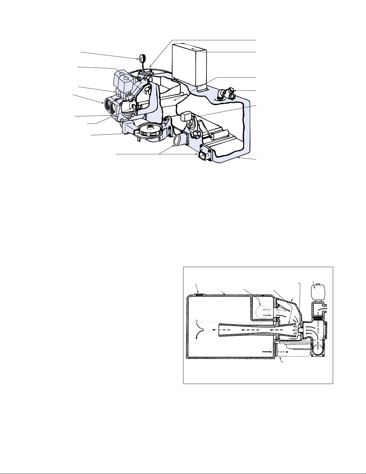
In operation the centrifugal pump circulates water (condensate) thru the multi-jet nozzle creating multiple jets of water
entering the venturi. These jets entrain air and gasses creating
a smooth steady vacuum in the nozzle body and in the condensate system. The air and gasses are separated in the
receiver and vented to atmosphere.
Low system vacuum or high water in the receiver will start the
pump to create vacuum and circulate water.
The discharge valve is opened by means of a solenoid in
response to the condensate level float switch. Controlled
opening of the discharge valve holds sufficient back pressure
in the nozzle body that the vacuum producer continues to
function even when discharging condensate (simultaneous
rating).
When the vacuum and float switches have been satisfied and
the pump stops, the check valve in the nozzle body closes,
preventing the return of air and water to the system.
An internal orifice permits the vacuum in the receiver and in
the system to slowly equalize. Note that the vent line on the
Series HV requires a check valve to prevent return of atmospheric air to the receiver. Without the check valve and orifice,
a system could develop high vacuum upon cooling holding the
check valve closed and thereby preventing flow of condensate
into the unit.
STRAINER
CONTROL PANEL
VENTURI
AIR VENT VALVE
FLOAT SWITCH
RECEIVER
MOUNTING PADS FOR DUPLEX
CENTRIFUGAL PUMPS
CENTRIFUGAL PUMP
MULTI-JET NOZZLE
DISCHARGE
MANIFOLD
SOLENOID
DISCHARGE VALVE
DISCHARGE
CHECK VALVE
VACUUM GAGE
DSK-1330
FIG. 1 SERIES HV VACUUM UNITS 25,000-60,000 EDR
FIG. 2 SERIES HV VACUUM PRODUCER
SOLENOID
DISCHARGE
AIR VENT
RECEIVER
MULTI-JET NOZZLES
INLET
VENTURI
DSK-1328
NOZZLE
BODY
CENTRIFUGAL PUMP
VALVE
Page 3
3
Receivers are non-code cast iron.
PRELIMINARY INSPECTION
Assure that there is no shipping damage.
Assure that nameplate ratings agree with job specifications
and actual conditions.
HANDLING
Use care in installing unit.
LOCATION
Place unit for easy access to all parts. Allow adequate space
for servicing. Check ambient conditions.
NOTICE / TEMPERATURE LIMITS
Motors are designed to operate in 104°F max. ambient.
Insulate or ventilate as required.
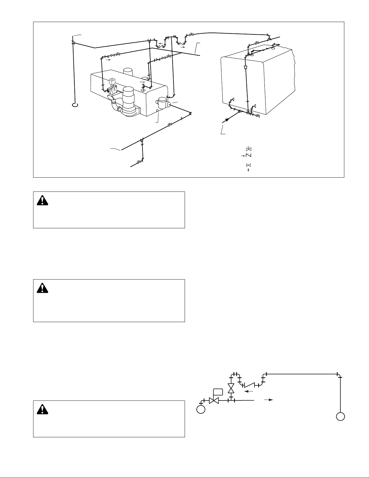
PIPING (GENERAL)
Pipe the unit per the Elementary Piping Diagram. Locate and
support piping so as to not load the discharge valve.
PIPING (Vent)
Install a vent pipe to atmosphere. Pipe to be size of vent port
on unit. Do not restrict or reduce vent opening or exceed 20
feet vertical height unless an overflow connection is provided.
Series HV Units require a check valve in the vent line as shown
on the piping diagram (furnished with unit).
PRIMING PORT
Provide a priming port as shown on piping diagram. Provide a
water supply for priming.
FLOAT SWITCHES
Floats are locked in place to prevent damage during shipment.
Remove shipping locks. Check factory settings. Floats are
adjustable for various levels of operation.
See page 7 for detailed instructions.
EQUALIZING LINE
An equalizing line must be installed with all Series HV units.
This line must be installed to prevent formation of a vacuum
on the radiation side of the system when steam stops flowing
in the mains. This vacuum may be higher than return line vacuum, which would prevent condensate from flowing back to
the pump. To correct this in an unzoned system, install equalizer line as shown in the piping diagram. To correct this in a
zoned system, install equalizer line for each zoned section or
install a vacuum breaker on supply line on radiation side of
each zone control valve.
CAUTION: UNIT LIFTING EYE
Use unit lifting eyes only to lift unit as shipped from
factory. Unit must be empty and disconnected from pipes,
anchors and other restraints. Use proper rigging procedures. Failure to follow these instructions could result in
injury or property damage.
CAUTION: NOT A CHEMICAL PUMP
Inject boiler feed compounds from chemical feed
tank into boiler feed piping – never into condensate tank.
Failure to follow these instructions could result in injury or
property damage.
WARNING: EXPLOSIBLE
Do not pressurize receiver. Isolate receiver during
leak test. Do not plug overflow. Do not restrict vent opening
to atmosphere. Open valves slowly. Failure to follow these
instructions could result in serious injury or death.
TO BOILER
FEED
SYSTEM
REDUCER
STRAINER
SERIES VLR DUPLEX
PIPING DIAGRAM
DRAIN
DRAIN
DRAIN
DV
PRIMING
OPENING
EQUALIZING LINE —
3
/4"
BOILER
FROM BOILER
FEED SYSTEM
— GATE VALVE
— DISCHARGE VALVE
DV
— STEAM OR PLUG COCK
— UNION
— CHECK VALVE
OPEN VENT ABOVE
BOILER WATER LINE
RETURN FROM
HEATING SYSTEM
EQUALIZING CONNECTIONS FOR ZONED SYSTEMS
ZONE CONTROL
VALVE
STEAM MAIN
M
TO ZONE
RETURN MAIN
FIG. 3
SERIES HV PIPING DIAGRAM
Page 4

4
PIPING (Returns)
Gravity return lines from system must be properly pitched
down to unit inlet. Returns must also be trapped to prevent
steam entry into the unit. An inlet basket strainer is
recommended.
Install gate valve in return line for testing pump shut off vacuum, closing off hot returns when cleaning strainer, etc. Do not
install check valve in return line. Avoid elbow or tee located
closer to strainer inlet than 10 times inlet diameter. If unavoidable relocate vacuum switches to top of nearest “dry” point on
return main unless a portion of return is below pump inlet an
accumulation tank is recommended. Accumulator tank may
not be necessary if low length of return is not lower than 24"
below pump inlet or longer than 30'. See TYPICAL PIPINGLOW RETURNS. (Page 5) High pressure steam traps should
empty into uninsulated flash tank where condensate will cool
before entering unit.
DISCHARGE LINE
Install union, check valve, steam cock and gate valve at unit in
each discharge line. Steam cock to be adjusted to cause
pump to operate at specified pressure. If discharge line is
more than 100' long, install pipe 1 or 2 times larger than discharge valve tapping.
ELECTRICAL WIRING & CONTROLS
Connect power wiring per NEC. Recheck nameplate vs. speci-
fications and conditions. All single phase motors have internal
thermal protection.
Three phase motors must use starters with properly sized
overload relays. Overload relays furnished are designed for
manual reset.
WARNING: HIGH VOLTAGE ELECTRICITY
Disconnect and lock out power before connecting or
servicing unit. Failure to follow these instructions could
result in serious injury or death.
PUTTING THE UNIT INTO SERVICE
1. Assure that the unit is piped in accordance with instructions.
2. Isolate tank before performing any system leak test. Do
not pressurize the tank as part of the leak test. Failure to
do this can result in serious injury or death.
3. Check floats for free operation.
4. Check power leads in accordance with wiring diagram
enclosed in control cabinet (when furnished).
5. Install drain plugs.
6. Fill receiver half full of water to prime pump(s) and prevent
possible damage to pump seals. Avoid freezing conditions
after unit receiver has been filled.
7. Check for proper rotation of all three phase motors.
Rotation must be clockwise looking down on the motor as
indicated by directional arrow on pump casting. If pump
runs backwards, interchange two wires (3 phase only).
8. Throttle plug cock in discharge line until pressure at pump
(while pump is discharging) approaches pump rated pressure. Tighten plug nut to secure adjustment.
9. Remove start-up label (below) from panel (if applicable)
after complying with instructions.
10. If possible, observe operation thru several cycles using
selector or vacuum switch settings as noted below.
WARNING: HIGH VOLTAGE
Disconnect and lock out power before connecting or
servicing unit. Failure to follow these instructions could
result in serious injury or death.
CAUTION: DO NOT RUN DRY.
SEAL DAMAGE MAY OCCUR.
Inspect pump seal regularly for leaks. Replace as required.
Failure to follow these instructions could result in injury or
property damage.
CAUTION: DO NOT REVERSE
Reverse operation can cause extensive damage to
pumps. Jog the motor to test for direction of rotation.
Failure to follow these instructions could result in injury or
property damage.
WARNING: EXPLOSIBLE
Do not pressurize receiver. Isolate receiver during
leak test. Do not plug overflow. Do not restrict vent opening
to atmosphere. Open valves slowly. Failure to follow these
instructions could result in serious injury or death.
ELECTRICIAN/INSTALLER/OPERATOR
REMOVE AND DESTROY THIS TAG AFTER —
1. ASSURING THAT ALL PUMPS ROTATE CLOCKWISE PER ARROWS
CAST ON VOLUTES. (JOG PUMP MOMENTARILY TO TEST – INTERCHANGE ANY TWO MOTOR POWER WIRES TO REVERSE 3PH
MOTORS.)
2. ASSURING THAT SHIPPING LOCKS HAVE BEEN REMOVED FROM ALL
FLOAT SWITCHES.
Page 5

5
SPECIAL PIPING ARRANGEMENTS FOR LOW RETURNS
(IF LIFT EXCEEDS 5 FEET, A MECHANICAL LIFT IS RECOMMENDED)
FIG. 4
FIG. 6
FIG. 5
FIG. 8
FIG. 9
FIG. 7
Page 6

OPERATION AND MAINTENANCE
Operators must be familiar with all sections of this manual to
understand the operation of the unit.
Hot water, steam and electricity can be hazardous.
Check motor nameplate for any lubrication requirements.
Pumps require no lubrication.
NOTICE / AUTO RESTART
Single phase motors will restart automatically after thermal
overload protector trips.
Overload thermal relays in starters must be reset manually.
A properly installed unit should function unattended for long
periods of time. Periodic checks to assure proper operation
are highly recommended. Refer to trouble shooting section
when necessary.
A variety of control options are available and are furnished in
accordance with user specifications. Refer to wiring diagrams
(when furnished) to determine control switch settings.
The inlet strainer (when furnished) is intended to protect the
pump and system. Periodic cleaning should be included in the
maintenance schedule. Check frequently in new systems.
GAGE GLASS MAINTENANCE (Vented System)
Clean gage glass as required using commercial glass cleaner.
Dilute muratic acid may be used if required (observe handling
precautions). Never clean gage glass with wire brushes,
scrapers or harsh abrasives.
Do not reuse gage glass or packings or seals.
Immediately replace glass which is broken, cracked, chipped,
scratched or otherwise damaged. Inspect periodically with a
bright concentrated light. Anything which glistens and catches
the fingernail or any star-shaped or crescent-shaped mark
which glistens is cause for replacement. Any gage glass which
appears cloudy or roughened and will not respond to cleaning
procedures should be replaced.
When replacing gage glass, use new packings specified for
this use. Install glass with sufficient end clearance for expansion (keep glass to metal clearance at each end) and tighten
nuts just enough to avoid leakage (do not over tighten).
WARNING: HIGH VOLTAGE
Disconnect and lock out power before connecting or
servicing unit. Failure to follow these instructions could
result in serious injury or death.
SAFETY INSTRUCTIONS
SEE COVER OF THIS MANUAL
WARNING: EXPLOSIBLE
Do not pressurize receiver. Isolate receiver during
leak test. Do not plug overflow. Do not restrict vent opening
to atmosphere. Open valves slowly. Failure to follow these
instructions could result in serious injury or death.
6
POSITION WHEN USED OPERATION
“Vacuum and Float” or “FL-Vac” Normal position
Pumps operate on either low
vacuum or high condensate
“Float Only” or “Float”
Sometimes used for night and week-end service. This Pump starts and stops on
setting not recommended for use with lift fitting. Condensate level change
“Continuous” or “Hand”
Testing and for unusually high
Continuous
lift conditions in return lines.
“Off” (Duplex Units only) Adjust controls, inspect pump Prevent operation of motor
SELECTOR OR VACUUM SWITCH SETTINGS
The vacuum switches are adjusted and tested at the factory
for proper operation. The vacuum switch on a single unit and
the lead switch of a duplex unit is set to close at 3" Hg vacuum and open at 8". The lag switch of a duplex unit is set to
close at 2
1
/2" and open at 8".
These settings are suitable for all normal installations including
those having an accumulator tank or lift fitting. If settings must
be readjusted refer to manufacturer’s instructions.
CAUTION: SUBSEQUENT DAMAGE
A unit showing symptoms of possible problems
(overflow, noise, leaks, vibrations, continual operation, etc.)
must be corrected immediately. Failure to follow these
instructions may result in full liability for subsequent injury
or property damage.
Page 7

PROPER ADJUSTMENT OF CONTROLS RESULTS
IN MINIMUM CONDENSATE IN RECEIVER.
CONTROLS ARE PRESET AT THE FACTORY BUT
MAY VARY DUE TO HANDLING DURING SHIPMENT.
1. Close the inlet gate valve and, with the discharge line
open, operate the pump on “continuous” or “hand” to
remove sufficient water to lower the level to about the 7
1
/2
inch level in the water level gauge glass measured from the
top of the lower gauge cock. If necessary, admit water to
obtain the 7
1
/2 inch level.
2. Open the disconnect switch(es).
3a.(Units equipped with one float switch.) Adjust the cut-in
point of the float switch by depressing the float arm slightly
and adjusting the stop so that the switch turns on when
the float arm is released.
3b.(Units equipped with two float switches.) Adjust the F1, or
lead, float switch in the manner described in 3a. Admit
water to a 1" higher level and adjust the F2, or stand-by,
float switch to cut in.
4. Run pump on “float or FL and VAC” unit float switch opens
and closes the discharge valve. The discharge valve is
closed when the water level in the gauge glass no longer
drops. This level should be at approximately the four inch
level. If not, adjust the float switch.
FLOAT SWITCH ADJUSTMENT PROCEDURES
7
Condensate enters the screen from the bottom and flows outward from the inside. Foreign matter intercepted by the screen
may drop into the large dirt pocket in the lower portion of the
strainer body; however, grease, oil, gasket material and other
foreign substances present in all heating systems are likely to
stick and clog the strainer screen. For this reason it may be
necessary to clean the strainer several times a week during
the first few months of operation.
To clean strainer proceed as follows: (1) open disconnect
switch(es), (2) close return line gate valve, (3) remove drain
plug, (4) remove cap screws, cover and screen, (5) clean
screen thoroughly, (6) flush strainer body and dirt pocket, (7)
inspect gasket, (8) reassemble.
While the pump is shut down inspect and clean the multi-jet
nozzles as follows: (1) drain receiver below nozzle level by
removing drain plug, (2) remove discharge manifold cover
plate and multi-jet nozzle, (3) clean nozzle, (4) inspect gasket
and reassemble, (5) reprime pump to half way level in gauge
glass, (6) close switches, (7) open return line gate valve slowly.
INLET BASKET STRAINER MAINTENANCE
VACUUM GAUGE TAPPING
VACUUM BREAKER TAPPING
CAPSCREWS
COVER
GASKET
SCREEN
STRAINER BODY
DRAIN PLUG
(ON REAR OF STRAINER)
THERMOMETER (ON FRONT OF STRAINER)
Page 8

8
PUMP SERVICE INSTRUCTIONS FOR VACUUM PRODUCING CENTRIFUGAL PUMPS
Vertical mounting puts motor above floor dirt and water.
Close coupled centrifugal pumps are designed for years of
trouble free service. Units have mechanical shaft seals and are
vertically mounted to put the motor above floor dirt and water.
1. Drain hurling chamber.
2. Shut-off and lock out power.
3. Make sure unit is cool enough that pump can be handled
safely. Open drain to remove remaining liquid.
4. Carefully remove pump drain plug and bleed line. Wait for
complete drainage.
5.Loosen the motor bracket to pump volute capscrews.
Assure that the pressure is relieved per caution note.
6.Complete the removal of the hardware. Remove pump/
motor assembly and place on work bench.
7. Remove self locking stainless steel capscrews and stainless steel washer (or self locking brass cap nut and
washer) that secure the impeller in place.
8. To remove impeller from motor shaft proceed as follows:
(1) Keyed Shafts. Remove impeller with gear puller or other
means which will not damage impeller or bend motor
shaft.
(2) Threaded Shafts. Hold end of motor shaft opposite
pump with large screwdriver or other suitable tool and
back impeller off with a rectangular bar or other flat tool
inserted between the vanes of the impeller.
9. Remove rotating part of seal from shaft, being careful not
break carbon face.
10. Remove capscrews holding motor bracket to motor and
remove bracket.
11. Remove stationary part of seal assembly, being careful not
to chip or break ceramic seal.
12. To install seal proceed as follows:
(1) Clean recess in bracket thoroughly. Coat recess and
“rubber” portion of seat with soap solution. Press seat
into recess firmly by hand making certain both parts
bottom evenly. If seal cannot be bottomed with fingers
place cardboard shipping disc on ceramic and force
into place with tool.
(2) Carefully place bracket in position on motor shaft with-
out displacing ceramic seat and secure bracket to
motor with capscrews.
(3) Place motor vertically with pump end up. Do not
attempt assembly of seal and impeller with shaft
horizontal.
(4) The “carbon” of rotating part of seal should not be
loose. If it is, hold in place with grease, Using clean, lint
free cloth, wipe mating surfaces perfectly clean. Soap
shaft and push seal onto shaft so that carbon will contact ceramic seal. If spacer is required, use grease to
cause spacer to adhere to bottom of seal after seal has
been put on shaft, Be sure spacer is on larger diameter
of shaft so that will not catch between shoulder and
impeller.
13. Replace impeller on shaft. Replace stainless steel washer
and secure impeller with capscrew or cap nut.
14. Place new gasket on pump volute and reassemble motor
and pump subassembly on pump volute.
15. Reconnect pump bleed line and motor wiring.
16. Close drain and slowly open inlet valves. See warning.
17. Jog to check motor rotation. See caution.
18. Observe operation thru several cycles.
CAUTION: PRESSURIZED SYSTEM
Operating system may contain very hot water. Close
inlet and open drains before servicing. When servicing,
loosen screws and move components to assure pressure is
relieved before
removing screws. Keep drains open during
servicing. Failure to follow these instructions could result in
injury or death.
CAUTION: HOT SURFACE
Surfaces are hot when system is in operation. Do not
touch hot receiver, let unit cool before servicing. Failure to
follow these instructions could result in serious injury or
death.
WARNING: HIGH VOLTAGE
Disconnect and lock out power before connecting
servicing unit. Failure to follow these instructions could
result in serious injury or death.
WARNING: EXPLOSIBLE
Do not pressurize receiver. Isolate receiver during
leak test. Do not plug overflow. Do not restrict vent opening
to atmosphere. Open valves slowly. Failure to follow these
instructions could result in serious injury or death.
CAUTION: DO NOT REVERSE
Reverse operation can cause extensive damage to
pumps. Jog the motor to test for direction of rotation.
Failure to follow these instructions could result in serious
injury or death.
CAUTION: DO NOT RUN DRY.
SEAL DAMAGE MAY OCCUR
Inspect pump seal regularly for leaks Replace as required.
Failure to follow these instructions could result in serious
injury or death.
WATER
SLINGER
MECHANICAL
SEAL
MOTOR BRACKET
VOLUTE
IMPELLER
WEAR RING
VIEW OF
THREADED
IMPELLER
2DPF03
Page 9

9
TROUBLESHOOTING SERIES HV UNITS
ALL UNITS ARE THOROUGHLY TESTED AT THE FACTORY BEFORE SHIPMENT AND SHOULD OPERATE SATISFACTORILY
WITHOUT FURTHER ADJUSTMENT IF PROPERLY INSTALLED AND IF NOT DAMAGED BY ROUGH HANDLING IN
TRANSIT. IF SYSTEM OR UNIT PERFORMANCE IS NOT SATISFACTORY, REFER TO THE FOLLOWING CHECK LIST.
PUMP WILL NOT START
1. The power supply has been interrupted, disconnect switch is
open or selector switches improperly positioned.
2. Insufficient condensate has accumulated to actuate float switch.
3. Vacuum is not low enough to actuate vacuum switch.
4. Incorrect voltage for motor. Check voltage and wiring with motor
characteristics.
5. Incorrect starter coil for power supply.
6. The overload relays in the starter have tripped out and must be
reset. Ambient temperature may be too high.
7. Check float switch, vacuum switch or other control for proper
operation.
8. Wiring to control panel is incorrect or connections are loose.
PUMP DOES NOT RETURN ALL CONDENSATE TO
BOILER FEED SYSTEM (SYSTEM FLOODS)
1. Pump is running backward looking down on motor. Rotation of 3
phase motors may be corrected by interchanging any two of the
three wires. Pump should run clockwise.
2. Steam traps are blowing through causing condensate to return at
excessive temperatures. If 160°F is exceeded the capacity of the
pump may be reduced below its rating. Traps should be repaired
or replaced.
3. The total pressure at the pump discharge is greater than the pressure for which the pump was designed. Check the total pressure
which includes the boiler pressure, the friction head and the static
head.
4. A valve in the discharge line between pump and boiler is closed or
throttled too tightly. Check valve is installed backwards.
5. Condensate is held up in system periodically by induced vacuum
in boiler or radiation then released in a flood when the pump
starts. Install equalizer line.
6. The strainer is dirty thus retarding flow. Refer to instructions for
cleaning.
7. The impeller eye is clogged with trash. Clean.
8. The bellows type discharge valve fails to open. This may be
caused by the solenoid valve remaining in a closed position, or
dirt becoming lodged in the pressure release line. Float switch
failure may also cause the discharge valve to remain shut.
Replace the bellows type discharge with the solenoid operated
discharge valve. If solenoid discharge valve has already been
installed the solenoid may be stuck shut or the float switch failed.
9. Systems with accumulator tanks should have equalizer line run
from accumulator tank to steam header NOT from accumulator
tank to pump receiver NOR from pump receiver to steam header.
Install vacuum breaker on accumulator tank, NOT on pump.
10. Pump is too small for the system.
VACUUM PUMP RUNS CONTINUOUSLY OR
FAILS TO PRODUCE SUFFICIENT VACUUM*
1. Selector switch is set on “continuous” or “hand”.
2. The temperature of the condensate is too high. Normal operating
condensate temperature should not exceed 160°F for rated
capacities. Correct the cause for high temperature condensate.
3. There are excessive leaks in the system piping preventing the
pump from producing sufficient vacuum to satisfy the vacuum
switch setting. To confirm this, make sure pump is primed, close
inlet valve, close equalizing line valve, plug other check valve on
this line, replace vacuum breaker with plug and observe shut-off
vacuum while pump is running.
4. The vacuum or float switch electrical contacts remain in closed
position. Adjust controls.
5. The nozzle, strainer, or impeller passageways are clogged with
foreign matter. Refer to instructions for cleaning.
6. A vacuum breaker is set too low. It should not admit air at a
vacuum within the range of the vacuum switch setting.
7.The pump has lost its hurling water. There should never be less
water than shown on float adjustment sketch. Loss of hurling
water may be caused by:
(1) Discharge valve leaks due to dirt or worn seat.
(2) Orifice in guide screw in discharge valve is closed.
(3) Discharge valve bellows is ruptured.
(4) Solenoid pilot valve remains in open position.
(5) Float switch failure.
Replace the bellows discharge valve with the solenoid operated
discharge valve. If the valve has already been replaced with the
solenoid operated discharge valve the loss of hurling water may
be caused by:
(1) Solenoid discharge valve leaks due to dirt or worn seat.
(2) Solenoid discharge valve stuck in open position.
(3) Check valve in nozzle body is leaking.
(4) Float switch failure.
8. Check valve in equalizer line or air vent line from receive or accumulator tank leaks, or is installed backwards.
9. One nozzle body check valve, Figure 2, page 2, on duplex pump
remains open, permitting air to recirculate.
10. Pump is too small for the system.
11. Lower float switch does not turn off. Float rests on receiver bottom and should be raised.
PUMP STARTS AND STOPS IN RAPID SUCCESSION
1. A check valve in return line. Remove.
2. A partially closed inlet valve. Valve should be a gate valve rather
than globe.
3. A lift in return line at or near the pump. Low return lines will fill
with condensate between pump operations. The inertia of the collected water may be quite great, and before the vacuum suddenly
produced by starting of the pump can set the water in motion, the
vacuum at the pump may reach the cut-off point of the vacuum
switch, thus stopping the pump. The vacuum quickly recedes as
the condensate moves into the receiver and the pump “trips in”
on vacuum control again, thus repeating this “hunting action”.
There are two ways to correct this difficulty:
(1) If the vacuum sensing line can be drained away from the vacuum
switch(es), connect this sensing line into the nearest “dry”
point in the return main so that the operation of the unit may
be governed by the vacuum in the system.
(2) If the nearest “dry” point on the return main is more than
2 ft. above the vacuum switch, relocate and reconnect the
switches to sense the vacuum at this point. If a separate selector switch for “Fl-Vac, “Float”, “Hand” operation is not already
furnished with the unit, one must be provided for each vacuum
switch for installation in control panel.
4. Elbow in return line too close to unit inlet. Correct as described in
item 3, or if there is no lift in the return line at or near the pump,
extend the 3/4" equalizing line to top of “dry” point on return main.
5. Equalizer line is improperly connected.
6. Strainer clogged with dirt. Clean strainer.
*Product life and product efficiency are greatly affected by system maintenance.
A tight (leak-free) system with properly functioning traps is essential for efficient
operation.
Page 10

PUMP MAKES NOISE
1. The pump is working against a lower pressure than designed for.
While pump is discharging, adjust square headed steam cock in
discharge line until pressure at pump approaches pump rated
pressure. Secure adjustment of steam cock by tightening lock
nut.
2. Excessive condensate temperature. Correct system conditions.
3. Magnetic hum or bearing noise in motor. Consult motor manufacturer’s authorized service station nearest pump location.
4. Starter chatters. Trouble is caused by low line voltage, poor connections, defective starter coil, or burned contacts.
5. Pump is running backward.
6. Water hammer when discharge valve closes:
(1) Adjust steam cock to reduce discharge velocity or
(2) Install surge chamber on boiler side of discharge check valve or
(3) Install additional check valve near boiler or
(4) Install discharge piping 1 or 2 sizes larger.
THE SYSTEM IS NOISY
1. Banging in the steam mains is usually caused by “imploding” in
condensate lying in low points in lines. These pockets can be
eliminated by “dripping” low points, properly supporting the pipe,
or by increasing the pitch of the lines.
2. Improper dripping of the steam mains and risers. Where there is a
rise in the steam main, or where it branches off into a riser, a drip
trap must be installed to the drain line.
3. The piping is too small to drain properly.
4. A defective trap is holding condensate in radiation.
5. A priming boiler is permitting a carry-over of water with the steam.
A priming boiler is caused by:
(1) Oil or other foreign matter. Clean boiler thoroughly.
(2) A reduction of the steam liberating area due to too high a
water level in the boiler. Reduce water line.
(3) Overloading. Reduce firing rate.
(4) Undersized steam outlet area, resulting in velocities in excess
of 15 to 25 ft. per second.
DEALER SERVICE
If trouble occurs that cannot be rectified, contact your local
B&G representative. He will need the following information in
order to give you assistance.
1. Complete nameplate data of pump and motor.
SEE RATING NAMEPLATE at right.
2. Vacuum readings.
3. Ampere draw of the motor.
4. A sketch of system piping.
HOFFMAN SPECIALTY
SERIES HV
MODEL
SERIAL
GPM PSI PUMP
CFM IN HG. PUMP
DWGS
POWER V. PH. HZ 60
CONTROL V. PH. 1 HZ 60
TOTAL LARGEST MOTOR
F.L. AMP F.L. AMP
DN0016
Morton Grove, Illinois 60053
TM
®
Xylem Inc.
8200 N. Austin Avenue
Morton Grove, Illinois 60053
Phone: (847) 966-3700
Fax: (847) 965-8379
www.xyleminc.com/brands/bellgossett
Bell & Gossett is a trademark of Xylem Inc. or one of its subsidiaries.
© 2012 Xylem Inc. DN0145D November 2012
 Loading...