

Page 1
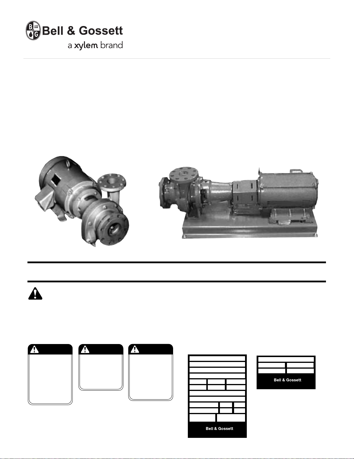
Domestic® Pump
2’ NPSH Horizontal Pumps
INSTRUCTION MANUAL
DN0141
REVISION D
Series HB17,™ HB35,™ DB,™ DB-F
™
SERIES DB
INSTALLER: PLEASE LEAVE THIS MANUAL FOR THE OWNER’S USE.
SERIES DBF
SAFETY
INSTRUCTIONS
This safety alert symbol will be used in this manual and on
the unit safety instruction decals to draw attention to safety
related instructions. When used, the safety alert symbol means
ATTENTION! BECOME ALERT! YOUR SAFETY IS INVOLVED!
FAILURE TO FOLLOW THESE INSTRUCTIONS MAY RESULT
IN A SAFETY HAZARD.
WARNING
ROTATING COMPONENTS
DISCONNECT AND LOCK OUT
POWER BEFORE SERVICING.
DO NOT OPERATE WITHOUT
ALL GUARDS IN PLACE.
CONSULT INSTALLATION
AND SERVICE INSTRUCTION
SHEET BEFORE OPERATING
OR SERVICING.
FAILURE TO FOLLOW
INSTRUCTIONS COULD
RESULT IN INJURY
OR DEATH.
P70642
WARNING
EYEBOLTS OR LIFTING
LUGS IF PROVIDED ARE
FOR LIFTING ONLY THE
COMPONENTS TO WHICH
THEY ARE ATTACHED.
FAILURE TO FOLLOW
INSTRUCTIONS COULD
RESULT IN INJURY
OR DEATH.
P70643
CAUTION
DO NOT RUN PUMP DRY,
SEAL DAMAGE MAY OCCUR.
INSPECT PUMP SEAL
REGULARLY FOR LEAKS,
REPLACE AS REQUIRED.
FOR LUBRICATION
REQUIREMENTS, CONSULT
SERVICE INSTRUCTIONS.
FAILURE TO FOLLOW
INSTRUCTIONS COULD
RESULT IN INJURY OR
PROPERTY DAMAGE.
P70644
If the decals as noted below are missing or are illegible contact
your local B&G representative for a replacement.
1. Electrical connections to be made by qualified Electrician in
accordance with all National, State and Local codes.
2. Motor must have properly sized starter with properly sized
heaters to provide overload and undervoltage protection.
3. If pump, motor or piping are operating at extremely high or
low temperatures, guarding or insulation is required.
4. Operating personnel should be trained in the operation of
pumps and associated systems (condensate, boiler feed, etc.).
TM
SERIES
MODEL
SERIAL
GPM PSI PUMP
CFM IN HG. PUMP
DWGS
POWER V. PH. HZ60
CONTROL V. PH. 1 HZ60
TOTAL LARGEST MOTOR
F.L. AMP F.L. AMP
DN0016
TM
Morton Grove, Illinois 60053
DOMESTIC® PUMPS
SERIES
SERIAL
DN0024
TM
GPM
PSI
Morton Grove, Illinois 60053
®
Page 2
DESCRIPTION
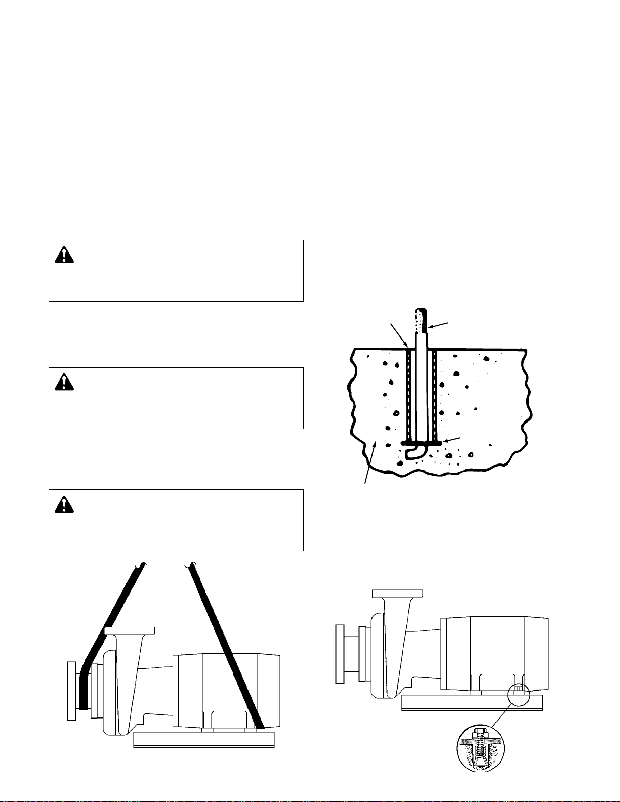
FOUNDATION BOLT
PIPE SLEEVE
WASHER
BUILT-UP
CONCRETE FOUNDATION
These horizontal end suction pumps feature a flow inducing
propeller and one or two impellers in series. These pumps
are supplied with or without mounting base (except for the
DB-F which requires a mounting base). All pumps are constructed with mechanical seals intended for high temperature
operations.
All models are bronze fitted with replaceable bronze wear rings.
APPLICATION
The 2' NPSHR rating of these pumps makes them uniquely
suited to pumping hot water. With 2 feet of static suction head,
the pumps will pump boiling water. Typical applications are on
condensate return and boiler feed systems.
These pumps are also well suited for general pumping service
of benign liquids.
WARNING: EXPLOSIBLE
Maximum suction pressure is 35 psi unless otherwise
specified by manufacturer. Do not exceed this pressure.
Failure to follow these instructions could result in serious
injury or death.
PRELIMINARY INSPECTION
Assure that there is no shipping damage.
Assure that nameplate ratings agree with job specifications and
actual conditions.
LOCATION
The best pump location for sound and vibration absorption
is on a concrete floor with sub soil underneath. If the pump
location is overhead, special precautions should be undertaken to reduce possible sound transmission, consult a sound
specialist.
If the pump is not installed on a closed system, it should be
placed as near as possible to the source of the liquid supply,
and located to permit installation with the fewest number of
bends or elbows in the suction pipe.
The installation must be evaluated to determine that the Net
Positive Suction Head Available (NPSHA) meets or exceeds the
Net Positive Suction Head Required (NPSHR) as stated by the
pump performance curve.
INSTALLATION
This pump is built to provide years of service if installed properly and attached to a suitable foundation. A base of concrete
weighing 21/2 times the weight of the pump is recommended.
(Check the shipping ticket for pump weight.)
If possible, tie the concrete pad in with the finished floor. Retain
access to pump mounting screws of DB-F pumps.
CAUTION: NOT A CHEMICAL PUMP
Inject boiler feed compounds from chemical feed tank
into boiler feed piping – never into pump suction. Failure to
follow these instructions could result in injury or property
damage.
PUMP LOCATION
Locate the pump so there is sufficient room for inspection,
maintenance and service. If the use of a hoist or tackle is
needed, allow ample head room.
WARNING: Eyebolts or lifting lugs if provided are for
lifting only the components to which they are
attached. If lifting of the entire pump is required, do so with
slings placed under the pump assembly as shown. Failure
to follow these instructions could result in injury or death.
To facilitate easy servicing, some type of expansion fitting
should be utilized. The female portion should be inserted into a
suitable hole in the floor so that its top surface is flush with the
floor surface. Thus, when the hold-down bolts are removed,
the motor can be removed by sliding it back from the pump.
(See below.)
2
Page 3
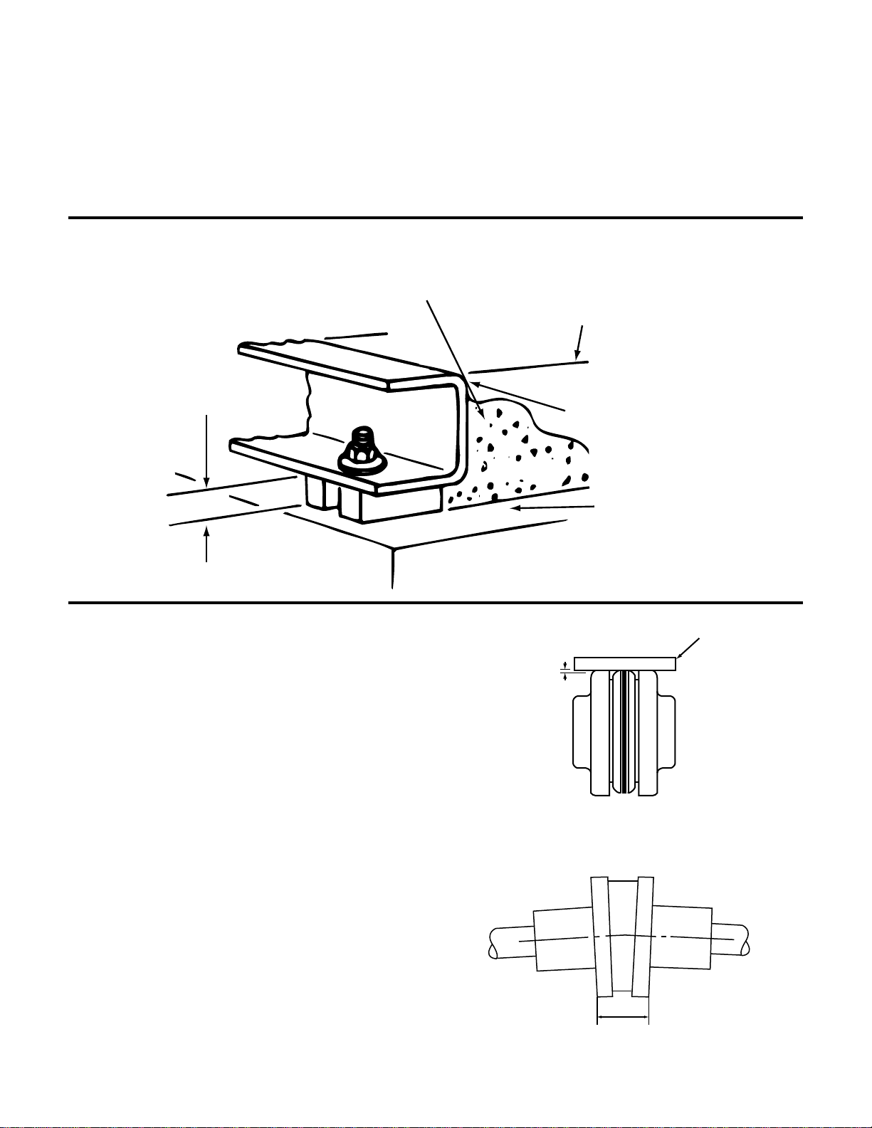
LEVELING
NOTE:
TO KEEP SHIMS IN PLACE
ALLOW NON-SHRINKING
GROUT TO FLOW AROUND
HOLD DOWN LUGS
ALLOW 1" FOR SHIMS.
PLACE ON BOTH SIDES
OF ANCHOR BOLTS
APPROX.
1" GAP
GROUT ONLY TO
TOP OF BASE RAIL
PUMP BASE RAIL
CONCRETE FOUNDATION
GROUT
PUMP BASE
STRAIGHT EDGE
.015 MAX
DISTANCES ACROSS
COUPLER FLANGES
SHOULD BE EQUAL
(CHECK 4 PLACES)
Place the pump on its concrete foundation supporting it with
steel wedges or shims totaling 1" in thickness. These wedges
or shims should be put on both sides of each anchor-bolt to
provide a means of leveling the base. (See below.)
IT IS VERY IMPORTANT THAT THE PUMP-BASE BE SET
LEVEL TO AVOID ANY MECHANICAL DIFFICULTIES WITH
THE MOTOR OR PUMP. THIS PUMP WAS PROPERLY
ALIGNED (IF FURNISHED WITH A MOTOR) AT THE FACTORY.
LEVELING OF PUMP BASE
ON CONCRETE FOUNDATION
HOWEVER, SINCE ALL PUMP BASES ARE FLEXIBLE THEY
MAY SPRING AND TWIST DURING SHIPMENT. DON’T PIPE
THE PUMP UNTIL IT IS REALIGNED. AFTER PIPING IS
COMPLETED AND AFTER THE PUMP IS GROUTED IN AND
BOLTED-DOWN, ALIGN IT AGAIN. IT MAY BE NECESSARY
TO RE-ADJUST THE ALIGNMENT FROM TIME TO TIME
WHILE THE UNIT AND FOUNDATION ARE NEW.
FLEXIBLE COUPLING ALIGNMENT
(SERIES DB-F PUMPS ONLY)
Check parallel alignment by placing a straight edge across the
two coupling flanges and measuring the maximum offset at
various points around the periphery of the coupling. DO NOT
rotate the coupling. If the maximum offset exceeds the .015,
realign the coupling.
Check angular alignment with a micrometer or caliper. Measure
from the outside of one flange to the outside of the other at
intervals around the periphery of the coupling. DO NOT rotate
the coupling. The difference between the maximum and minimum must not exceed .056".
If a correction is necessary, be sure to recheck the parallel
alignment.
(Note: For maximum life, keep misalignment values as near to
zero as possible.)
If the coupling employs the two-piece sleeve with the wire ring,
force the ring into its groove in the center of the sleeve. It
may be necessary to pry the ring into position with a blunt
screwdriver.
All alignment should be done by moving or shimming the motor
only. Adjustments in one direction may alter alignment in
another. Therefore, check alignment in all directions after a correction is made.
If couplings are to operate at speeds higher than 1800 RPM,
greater accuracy of shaft alignment will be required. A dial indicator should then be used.
CHECK PARALLEL ALIGNMENT
ANGULAR ALIGNMENT CHECK
3
Page 4
GROUTING
After the pump has been leveled, securely bolted to the floor,
and properly aligned, a good grade of non-shrinking grout
ELECTRICAL WIRING & CONTROLS
Connect power wiring per NEC. Recheck nameplate vs. specifications and conditions. All single phase motors have internal
thermal protection.
WARNING: HIGH VOLTAGE ELECTRICITY
Disconnect and lock out power before connecting or
servicing unit. Failure to follow these instructions could
result in serious injury or death.
should be poured inside the pump base. To hold wedges or
shims in place, allow the grout to flow around them.
Three phase motors must use starters with properly sized overload relays. Overload relays furnished are designed for manual
reset.
ROTATION
Pump rotation is clockwise when viewed from back of the
motor. An arrow is also located on the motor bracket or motor
to show the direction of rotation.
PIPING
Always install a section of straight pipe between the suction
side of the pump and first elbow. This reduces turbulence of
the suction by straightening out the flow of liquid before it
enters the pump. The length should be equal to five times the
diameter of the pipe. A Bell & Gossett suction diffuser can be
used if there is not adequate room for a straight suction line.
Be sure to eliminate any pipe-strain on the pump. Support the
suction and discharge pipes independently by use of pipe
hangers near the pump. Line up the vertical and horizontal
piping so that the bolt-holes in the pump flanges match the
bolt-holes in the pipe flanges. DO NOT ATTEMPT TO SPRING
THE SUCTION OR DISCHARGE LINES INTO POSITION.
Bearing wear will result if suction or discharge lines are forced
into position. The code for Pressure Piping (A.S.A.B. 31.1) lists
many types of supports available for various applications.
PUTTING THE UNIT INTO SERVICE
1. Assure that the unit is piped in accordance with instructions.
WARNING: EXPLOSIBLE
Maximum suction pressure is 35 psi unless otherwise
specified by manufacturer. Do not exceed this pressure.
Failure to follow these instructions could result in serious
injury or death.
2. Validate that the connected system is ready to operate.
3. Connect electrical supply per National Electrical Code.
WARNING: HIGH VOLTAGE
Disconnect and lock out power before connecting or
servicing unit. Failure to follow these instructions could
result in serious injury or death.
4. Install drain plugs.
5. Prime pump and bleed air from system. Avoid freezing
conditions after pump has been primed.
6. Check for proper rotation of all three phase motors.
Rotation must be clockwise looking down on the motor as
indicated by directional arrow on pump casting. If pump
runs backwards, interchange two wires (3 phase only).
4
As a rule, ordinary wire or band hangers are not adequate to
maintain alignment. It is very important to provide a strong,
rigid support for the suction and discharge lines.
Where considerable temperature changes are anticipated,
fittings for absorbing expansion should be installed in the system in such a way as to avoid strain on the pump.
A check valve and an isolation/throttling valve should be
installed at the discharge of the pump.
NOTES:
1. When installing the pump, suction and discharge gauge
ports should be installed in the pipeline.
2. The pipeline should have isolation valves around the pump
and have a drain valve in the suction pipe.
3. When installing the suction and discharge connections to a
threaded pump housing the use of PTFE tape sealer or a
high quality thread sealant is recommended.
CAUTION: DO NOT REVERSE
Reverse operation can cause extensive damage to
pumps. Jog the motor to test for direction of rotation. Failure
to follow these instructions could result in serious injury or
property damage.
7. Throttle plug cock in discharge line until pressure at pump
(while pump is discharging) approaches pump rated pressure. Secure adjustment.
CAUTION: DO NOT RUN DRY.
SEAL DAMAGE MAY OCCUR.
Inspect pump seal regularly for leaks. Replace as required.
Failure to follow these instructions could result in injury or
property damage.
8. Bleed all air from the volute. Where appropriate, use an
air bleed line to a tank ahead of the pump or to the pump
suction.
9. If possible, observe operation thru several cycles.
Page 5

OPERATION AND MAINTENANCE
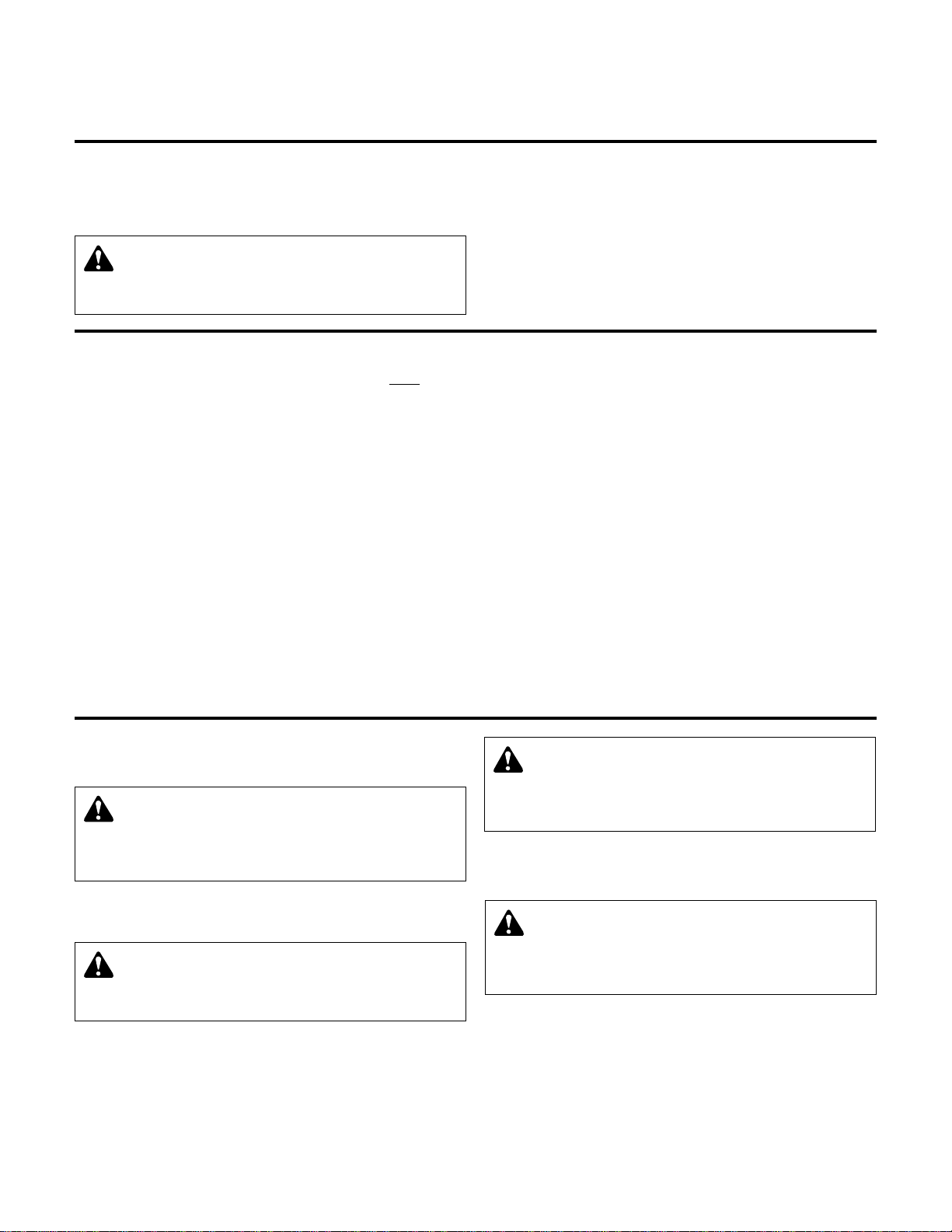
Retaining
Ring
1.062
Operators must be familiar with all sections of this manual to
understand the operation of the unit.
Hot water, steam and electricity can be hazardous.
SAFETY INSTRUCTIONS
SEE COVER OF THIS MANUAL
WARNING: EXPLOSIBLE
Maximum suction pressure is 35 psi unless otherwise
specified by manufacturer. Do not exceed this pressure.
Failure to follow these instructions could result in serious
injury or death.
WARNING: HIGH VOLTAGE
Disconnect and lock out power before connecting or
servicing unit. Failure to follow these instructions could
result in serious injury or death.
Check motor nameplate for any lubrication requirements.
NOTICE/AUTO RESTART
Single phase motors will restart automatically after thermal
overload protector trips.
Overload thermal relays in starters must be reset manually.
LUBRICATION
While pump is running regrease pump bearing with #2
lithium base petroleum grease about every 2500 hours of operation or every 6 months whichever occurs first.
Lubricate motor per motor manufacturer’s instructions.
GENERAL INSTRUCTIONS
1. Keep this pump and motor properly lubricated.
2. When there is a danger of freezing, drain the pump.
3. Inspect pump regularly for leaky seals or gaskets and
loose or damaged components. Replace or repair as
required.
SEAL REVISION
As of June 1997, DB and DB-F pumps use a Type 2 seal. This
seal is interchangeable with pumps that pre-date this cut-off
date. Regardless of date of manufacture of the pump, when
installing the Type 2 seal, the retaining ring is oriented with the
large OD facing the seal. (See illustration.)
CAUTION: SUBSEQUENT DAMAGE
A unit showing symptoms of possible problems (overflow, noise, leaks, vibrations, continual operation, etc.) must
be corrected immediately. Failure to follow this instruction
may result in full liability for subsequent injury or property
damage.
Specific maintenance and service instructions follow.
PUMP SERVICE INSTRUCTIONS FOR SERIES DB AND DB-F PUMP ENDS
1. Close pump isolation valve or system return line valve.
Operate pump momentarily to discharge as much water as
possible. Close pump discharge valve.
CAUTION: HOT SURFACES
Surfaces may be hot when system is in operation. Do
not tough exposed components, let unit cool before servicing. Failure to follow these instructions could result in serious injury or death.
2. Shut-off and lock out power.
WARNING: HIGH VOLTAGE
Disconnect and lock out power before connecting or
servicing unit. Failure to follow these instructions could
result in serious injury or death.
4. Carefully remove pump drain plug and air relief tube. Wait
for complete drainage.
5. Loosen both the discharge connection and the suction
housing to pump volute fasteners. Assure that pressure is
relieved per caution note.
CAUTION: PRESSURIZED SYSTEM
Operating system may contain very hot water under
pressure. Close inlet and open drains before servicing.
When servicing, loosen screws and move components to
assure pressure is relieved before removing screws. Keep
drains open during servicing. Failure to follow these instructions could result in injury or property damage.
3. Make sure unit is cool enough that pump can be handled
safely. Open drain to remove remaining liquid.
5
Page 6

PUMP SERVICE INSTRUCTIONS FOR SERIES DB AND DB-F PUMP ENDS cont.’d
SEAL COLLAR
2ND STAGE VOLUTE
MECHANICAL
SEAL COLLAR
MECHANICAL SEAL
2ND STAGE IMPELLER
DIAPHRAM
W/ WEAR RING
PIN
SHAFT EXTENSION
WASHER
SET SCREW
FIRST STAGE VOLUTE
FIRST STAGE
IMPELLER
SUCTION
HOUSING
PIN
PROPELLER
DIFFUSER
15
16
6. Remove discharge connection and suction connection.
Unbolt motor and or pump from base. Place assembly on
workbench.
7. Remove suction housing and then axial flow impeller,
shaft, and straightening vanes in the following manner:
Remove axial flow impeller set screws. Remove the axial
flow impeller, remove the straightening vanes, and
unscrew the shaft extension.
8. Remove cap screws holding pump volute and motor
bracket together. Remove volute by lifting straight away
from motor and bracket assembly.
9. Remove first centrifugal impeller by inserting two pry bars
between motor bracket and impeller on opposite sides of
impeller, being careful to pry equally, and ONLY WHERE
THE SHROUD OR THE IMPELLER IS SUPPORTED BY A
VANE. Lift off the diaphragm plate and wearing rings as an
assembly. Remove second centrifugal impeller, using a
puller. The machined groove on the impeller hub is for this
purpose.
10. To install new seal proceed as follows:
(1) Thoroughly clean recess in head. Moisten or soap the
“rubber” portion of seal. Press rubber and ceramic into
recess firmly by hand making certain both parts bottom
evenly. If seat cannot be bottomed with fingers place
the cardboard shipping disc on seat and force into
place with flat tool. Wipe clean with soft clean cloth to
remove dirt or excess soap.
(2) Carefully place head into position on motor shaft with-
out displacing ceramic seat, and secure bracket to
motor with cap screws.
(3) Place motor vertically with pump end up. Do not
attempt reassembly of pump with the shaft horizontal.
(4) The “carbon” of the rotating part of the seal should not
be loose. If it is, hold in place with grease. Using a
clean, lint-free cloth, wipe mating surfaces, perfectly
clean. Soap the shaft and push seal onto shaft so that
it touches the carbide seat.
(5) Replace seal collar as close as possible to original
position, and tighten the set screw.
11. Replace second impeller on shaft, being careful to bottom
it on shaft shoulder. Replace diaphragm plate with its
wearing rings, and replace first impeller. Reassemble
pump volute to bracket.
12. Reassemble propeller. Tighten thoroughly.
13. Reassemble straightening vanes, being careful to locate
properly on pin. Reassemble axial flow impeller and
tighten the set screws holding it to the propeller stem.
Reassemble suction housing using new gasket.
14. Reposition the pump in place, and bolt down. Reconnect
discharge and suction.
15. Reconnect air relief tubing and motor wiring.
NOTE: See page 4 for additional DB-F instructions
(Coupler Alignment).
CAUTION: DO NOT RUN DRY.
SEAL DAMAGE MAY OCCUR.
Inspect pump seal regularly for leaks. Replace as required.
Failure to follow these instructions could result in injury or
property damage.
16. Close drain and slowly open inlet gate valves.
WARNING: EXPLOSIBLE
Do not pressurize receiver. Do not plug overflow. Pipe
vent opening to atmosphere. Do not restrict. Open valves
slowly. Failure to follow these instructions could result in
serious injury or death.
17. Three phase motors should be started momentarily to
check rotation. If pump runs backward, interchange any
two motor leads. (Any electrical service should be performed by a qualified electrician).
CAUTION: DO NOT REVERSE
Reverse operation can cause extensive damage to
pumps. Jog the motor to test for direction of rotation. Failure
to follow these instructions could result in serious injury or
property damage.
18. Observe operation thru several cycles.
2DPB03
SERIES DB CROSS SECTION
PUMP SERVICE INSTRUCTIONS FOR SERIES HB17 AND HB35 PUMPS
1. Close pump isolation valve or system return line valve.
not tough exposed components, let unit cool before servicing. Failure to follow these instructions could result in serious injury or death.
6
Operate pump momentarily to discharge as much water as
possible. Close pump discharge valve.
CAUTION: HOT SURFACES
Surfaces may be hot when system is in operation. Do
2. Shut-off and lock out power.
WARNING: HIGH VOLTAGE
Disconnect and lock out power before connecting or
servicing unit. Failure to follow these instructions could
result in serious injury or death.
3. Make sure unit is cool enough that pump can be handled
safely. Open drain to remove remaining liquid.
Page 7

PUMP SERVICE INSTRUCTIONS FOR SERIES HB17 AND HB35 PUMPS cont.’d
MECHANICAL
SEAL
M & R
BRACKET
VOLUTE W/
WEAR RING
IMPELLER
PROPELLER STEM
PIN
WASHER
SET SCREW
PROPELLER CAP
SET SCREW
PROPELLER
SUCTION HOUSING
DIFFUSER
ROTATED FOR CLARITY
DISCHARGE FLANGE
LOCKING CAPSCREW
PROPELLER SUCTION
CASTING
PROPELLER CAP
PROPELLER
DIFFUSER
SHAFT EXTENSION
4. Carefully remove pump drain plug and air relief tube. Wait
for complete drainage.
5. Loosen both the discharge connection and the suction
housing to pump volute fasteners. Assure that pressure is
relieved per caution note.
CAUTION: PRESSURIZED SYSTEM
Operating system may contain very hot water under
pressure. Close inlet and open drains before servicing.
When servicing, loosen screws and move components to
assure pressure is relieved before removing screws. Keep
drains open during servicing. Failure to follow these instructions could result in injury or property damage.
6. Complete the removal of the above hardware. Remove
pump/motor assembly and place on work bench.
7a. Remove the suction housing capscrews and separate the
pump/motor assembly from the suction housing. Note, the
diffuser should separate from the suction housing to allow
the pump/motor assembly to be removed.
7b. Remove propeller, propeller stem and diffuser from the
assembly as follows: Keyed Motor Shafts (5HP and larger).
Remove propeller set screws. Remove propeller, remove
diffuser, and unscrew the propeller stem.
8. Remove capscrews holding motor bracket and pump
volute together. Remove motor and bracket assembly
from volute by lifting straight away from volute.
9. To remove impeller from the motor shaft proceed as
follows: Keyed Shafts. Remove impeller with gear puller or
other means which will not damage impeller or bend motor
shaft.
10. Remove rotating part of seal from shaft, being careful not
to break carbon face.
11. Remove capscrews holding motor bracket to motor and
remove bracket.
12. Remove stationary part of seal assembly, being careful not
to chip or break ceramic seal.
13. To install seal proceed as follows:
(1) Clean recess in bracket thoroughly. Coat recess and
“rubber” portion of seat with soap solution. Press seat
into recess firmly by hand making certain both parts
bottom evenly. If seat cannot be bottomed with fingers
place cardboard shipping disc on ceramic and force
into place with flat tool.
(2) Carefully place bracket into position on motor shaft
without displacing ceramic seat and secure bracket to
motor with capscrews.
(3) Place motor vertically with pump end up. Do
not attempt assembly of seal and impeller with shaft
horizontal.
(4) The “carbon” of rotating part of seal should not be loose.
14. Place impeller on shaft. Make sure impeller is seated.
15. Reassemble volute to bracket.
If it is, hold in place with grease. Using clean, lint free
cloth, wipe mating surfaces perfectly clean. Soap shaft
and push seal onto shaft so that carbon will contact
ceramic seal. If spacer is required, use grease to cause
spacer to adhere to bottom of seal after seal has been
put on shaft. Be sure spacer is on larger diameter of shaft
so that it will not catch between shoulder and impeller.
SERIES HB17 CROSS SECTION
SERIES HB-35 CROSS SECTION
16. Install stem over drive pin in impeller eye. Tighten lock nut.
17. Set stem to .004 TIR.
18. Install diffuser.
19. Install propeller and tighten set screws.
19a.Install propeller cap and tighten set screws.
20. Using new gasket and noting alignment pin, install assembly on suction housing.
21. Install suction housing and discharge fasteners and tighten.
22. Reconnect pump bleed line and motor wiring.
CAUTION: DO NOT RUN DRY.
SEAL DAMAGE MAY OCCUR.
Inspect pump seal regularly for leaks. Replace as required.
Failure to follow these instructions could result in injury or
property damage.
23. Close drain and slowly open inlet valves.
WARNING: EXPLOSIBLE
Do not pressurize receiver. Do not plug overflow. Pipe
vent opening to atmosphere. Do not restrict. Open valves
slowly. Failure to follow these instructions could result in
serious injury or death.
24. Jog to check motor rotation.
CAUTION: DO NOT REVERSE
Reverse operation can cause extensive damage to
pumps. Jog the motor to test for direction of rotation. Failure
to follow these instructions could result in serious injury or
property damage.
25. Observe operation thru several cycles.
7
Page 8
DOMESTIC® PUMPS
Bell & Gossett
Morton Grove, Illinois 60053
Xylem Inc.
8200 N. Austin Avenue
Morton Grove, Illinois 60053
Phone: (847) 966-3700
Fax: (847) 965-8379
www.xyleminc.com/brands/bellgossett
Bell & Gossett is a trademark of Xylem Inc. or one of its subsidiaries.
© 2012 Xylem Inc. DN0141D November 2012
 Loading...