

Page 1
Domestic® Pump
WARNING
Vacuum Heating Units
INSTRUCTION MANUAL
DN0136
REVISION C
Series VCD™ and VCL
INSTALLER: PLEASE LEAVE THIS MANUAL FOR THE OWNER’S USE.
™
SAFETY
INSTRUCTIONS
This safety alert symbol will be used in this manual and on
the unit safety instruction decals to draw attention to safety
related instructions. When used, the safety alert symbol means
ATTENTION! BECOME ALERT! YOUR SAFETY IS INVOLVED!
FAILURE TO FOLLOW THESE INSTRUCTIONS MAY RESULT
IN A SAFETY HAZARD.
DO NOT PRESSURIZE TANK.
ISOLATE TANK DURING LEAK TEST.
DO NOT RESTRICT VENT.
DO NOT PLUG OVERFLOW.
OPEN INLET VALVES SLOWLY.
EXPLOSIBLE
(2) All Units
DN0483 (Small) - DN0484 (Large)
DO NOT USE AS A FLASH TANK.
FAILURE TO FOLLOW
INSTRUCTIONS COULD RESULT
IN SERIOUS INJURY OR DEATH.
EXPLOSIBLE
ISOLATE TANK
DURING LEAK TEST
(2) All Units
DN0485 (Small)
DN0486 (Large)
If the decals as noted below are missing or are illegible contact
your local B&G representative for a replacement.
1. Electrical connections to be made by qualified Electrician in
accordance with all National, State and Local codes.
2. Motor must have properly sized starter with properly sized
heaters to provide overload and undervoltage protection.
3. If pump, motor or piping are operating at extremely high or
low temperatures, guarding or insulation is required.
4. Operating personnel should be trained in the operation of
vacuum/condensate return units.
TM
WARNING
SERIES HV
MODEL
SERIAL
GPM PSI PUMP
CFM IN HG. PUMP
DWGS
POWER V. PH. HZ 60
CONTROL V. PH. 1 HZ 60
TOTAL LARGEST MOTOR
F.L. AMP F.L. AMP
DN0016
DN0116 Units with Panel
TM
Morton Grove, Illinois 60053
CAUTION
DO NOT RUN PUMP DRY,
SEAL DAMAGE MAY OCCUR.
INSPECT PUMP SEAL
REGULARLY FOR LEAKS,
REPLACE AS REQUIRED.
FOR LUBRICATION
REQUIREMENTS, CONSULT
SERVICE INSTRUCTIONS.
FAILURE TO FOLLOW
INSTRUCTIONS COULD
RESULT IN INJURY OR
PROPERTY DAMAGE.
P70644 All Units
P70644
Page 2
2
DESCRIPTION
The Series VCD and Series VCL vacuum heating units are
designed to serve the dual purpose of pumping accumulated
condensate back to the boiler feed tank and maintaining
vacuum in the condensate system.
These units have separate compartments for the vacuum producer (the hurling water chamber) and for the condensate (the
condensate receiver).
The 25VCD and 50VCD models have both compartments integrally cast in one casting while the 100 and 150 VCD models
have separate compartments bolted together with external lift
pipes connecting them.
Series VCL units are customized to user specifications and
constructed using a choice of rectangular cast iron condensate
receivers, underground receivers, or cylindrical steel receivers.
In the case of steel condensate receivers, the vacuum unit can
be mounted on this receiver or mounted separately and field
piped. All models will have one or two condensate pumps and
one or two vacuum pumps as specified.
A variety of control options are available and furnished as specified. When control panels are factory supplied, electrical diagrams are shipped in the cabinets.
Receivers and hurling chambers are non-code cast iron or
steel.
PRELIMINARY INSPECTION
Assure that there is no shipping damage.
Assure that nameplate ratings agree with job specifications and
actual conditions.
HANDLING
Use care in installing unit. Utilize Lifting Eyes equally when
slinging.
LOCATION
Place unit for easy access to all parts. Allow adequate space
for servicing. Check ambient conditions.
NOTICE/TEMPERATURE LIMITS
Motors are designed to operate in 104°F (40°C) max. ambient.
Insulate or ventilate as required.
PIPING (General)
Pipe the unit per the Representative Piping Diagram. Locate
and support piping so as to not load the pump discharge.
WARNING: EXPLOSIBLE
Do not pressurize receiver. Isolate receiver during leak
test. Do not plug overflow. Do not restrict vent opening to
atmosphere. Open valves slowly. Failure to follow these
instructions could result in serious injury or death.
CAUTION: UNIT LIFTING EYE
Use unit lifting eyes only to lift unit as shipped from
factory. Unit must be empty and disconnected from pipes,
anchors and other restraints. Use proper rigging procedures. Failure to follow these instructions could result in
injury or property damage.
CAUTION: NOT A CHEMICAL PUMP
Inject boiler feed compounds from chemical feed tank
into boiler feed piping – never into condensate tank. Failure
to follow these instructions could result in injury or property
damage.
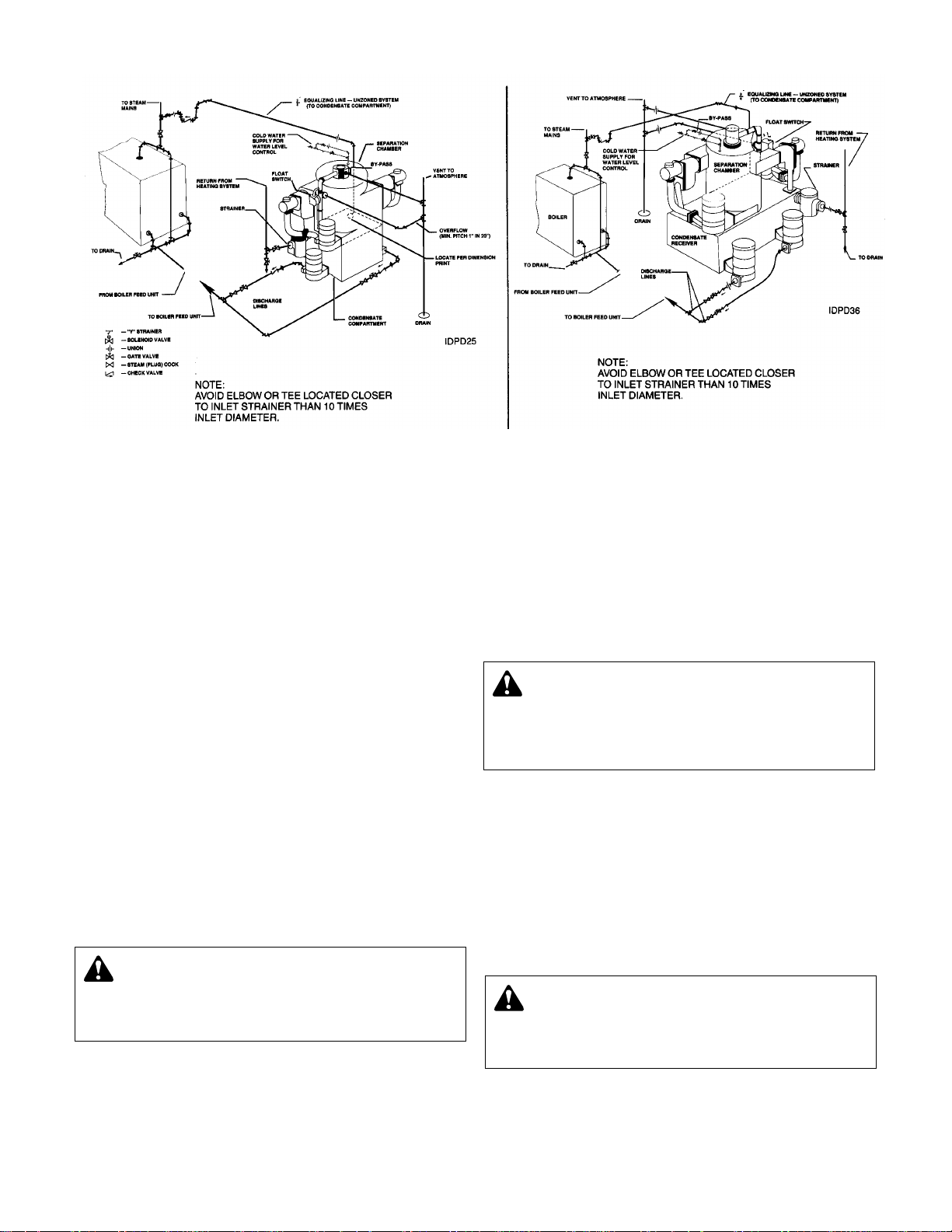
FIG. 1
100 & 150 VCD CONFIGURATION
SERIES VCL (NOT SHOWN) USES SIMILAR PIPING
25 & 50 VCD CONFIGURATION
REPRESENTATIVE PIPING DIAGRAM
Page 3
PIPING (Returns)
Gravity return lines from system must be properly pitched down
to unit inlet. Returns must also be trapped to prevent steam
entry into the unit. An inlet basket strainer is recommended.
SUCTION PIPING
Suction piping between the condensate receiver and the
vacuum producer should be at least as large as the inlet to the
vacuum producer.
PIPING (Vent)
Install a vent pipe to atmosphere. Pipe to be size of vent port
on unit. Do not restrict or reduce vent opening or exceed 20
feet vertical height unless an overflow connection is provided.
PIPING (Overflow)
Pipe overflow port to drain using an overflow loop when con-
densate temp will exceed 200ºF. (93°C).
The overflow port on the hurling chamber acts as the overflow
for both the vacuum producer and condensate return units.
Pipe to a suitable drain.
Series VCL units have a high level (overflow control) float
switch to start the vacuum pumps when the lower receiver is at
the “full” level. The vacuum pumps will siphon condensate from
the receiver into the hurling chamber.
Excess condensate will then overflow out of the hurling chamber to drain.
FLOAT SWITCHES & MECHANICAL ALTERNATORS
Floats are locked in place to prevent damage during shipment.
Remove shipping locks. Check factory settings. Floats and
mechanical alternators are adjustable for various levels of operation. The lead pump should start with tank
3
/4 full and shut off
at 2" or more above pump inlet. Lag pump should start before
the tank overflows. Settings should avoid “short cycling” of the
pump.
Vacuum switch adjustment is explained on the following page.
An electric alternator (when furnished) must operate off the
lead vacuum switch.
ELECTRICAL WIRING & CONTROLS
Connect power wiring per the National Electrical Code.
Recheck nameplate vs specifications and conditions. All single
phase motors have internal thermal protection.
Three phase motors must use starters with properly sized overload relays. Overload relays furnished are designed for manual
reset.
EQUALIZING LINE
A vacuum may be formed on radiation side of system when
steam stops flowing in mains. This vacuum may be higher than
return line vacuum, which would prevent condensate from
flowing back to pump. To correct this in an unzoned system,
install equalizer line as shown. To correct this in a zoned system, install equalizer line for each zoned section or install a
vacuum breaker on supply line on radiation side of each zone
valve.
ACCUMULATOR TANK
An accumulator tank may be used to facilitate lifting conden-
sate. The accumulator tank will be fitted with a float switch to
start the vacuum pump as accumulator fills. The vacuum pump
will then siphon condensate into the condensate receiver.
The vacuum sensor line in an accumulator tank system must
sense the vacuum in the accumulator tank as shown on the low
return piping diagrams. (Figure 9, page 5.)
3
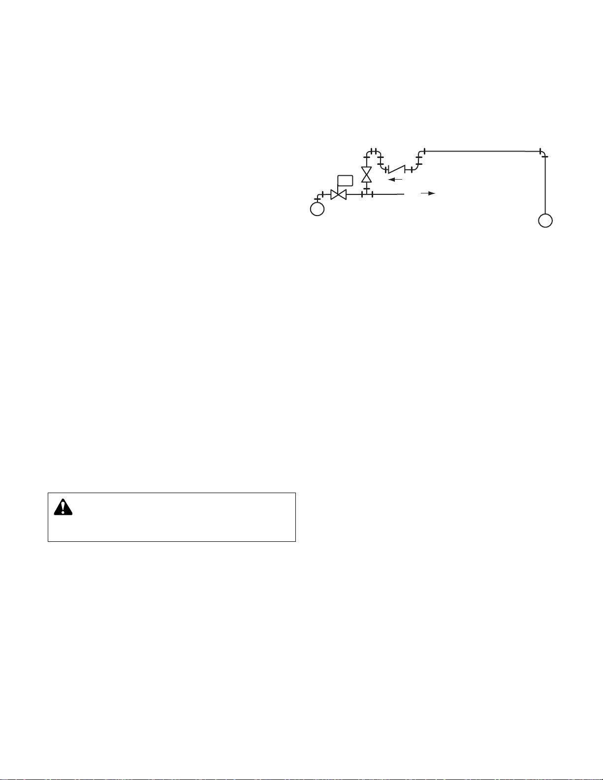
ZONE CONTROL
VALVE
STEAM MAIN
M
TO ZONE
RETURN MAIN
WARNING: HIGH VOLTAGE ELECTRICITY
Disconnect and lock out power before connecting or
servicing unit. Failure to follow these instructions could
result in serious injury or death.
FIG. 2 EQUALIZING CONNECTIONS FOR ZONED SYSTEMS
Page 4
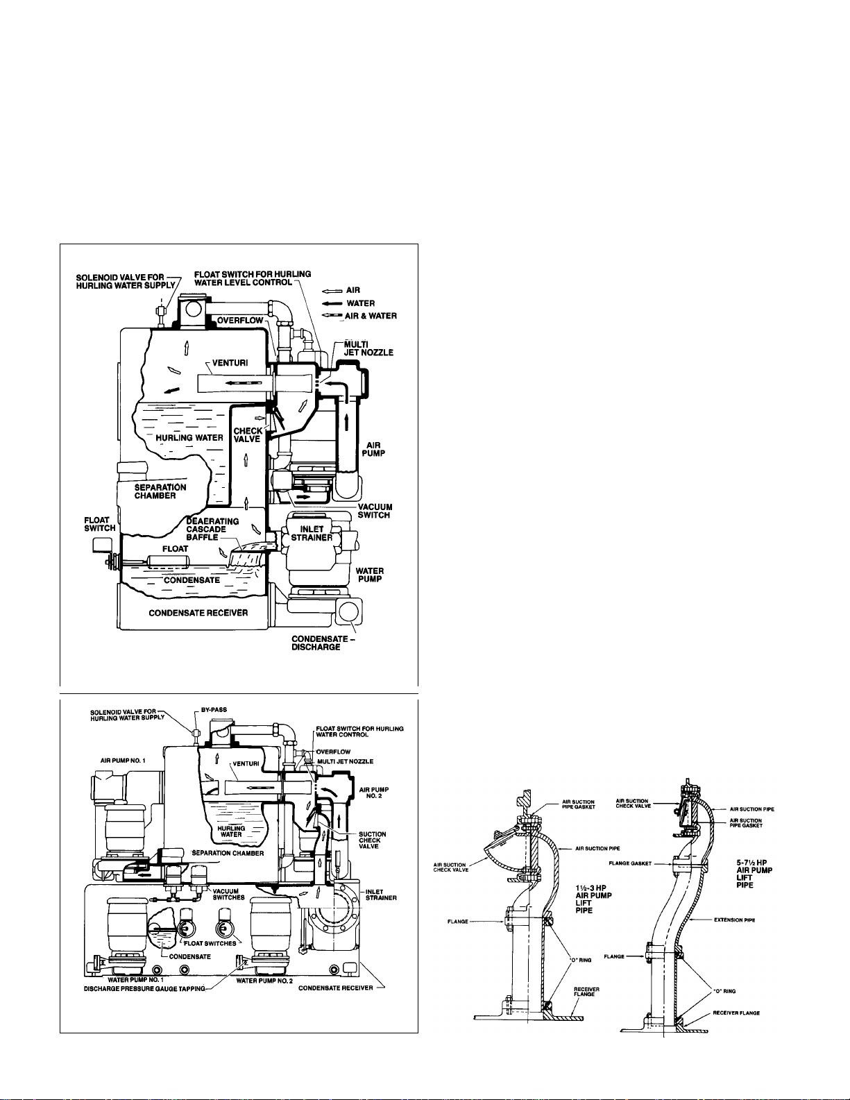
SEQUENCE OF OPERATION
There are two separate and independent cycles of operation
in the VCD design – one of air evacuation and the other for
condensate return. This is accomplished by completely separating the air pumps from the condensate storage receiver
and water pumps. Fig 3 below illustrates a single, two compartment receiver, divided horizontally, where the air pumps
operate from the upper compartment or separation chamber
while the water pumps operate from the lower compartment
or condensate receiver. The unit below is similar except that
the air pump separation chamber and condensate receiver are
separate units, connected as shown in Figure 4. The operation
for both types of construction is identical.
AIR EVACUATION CYCLE
The independent air evacuation cycle begins when the vacuum
switch, responding to system requirements, starts the centrifugal “air” pump. This pump circulates “hurling” water from the
separation chamber through the multi-jet nozzle, venturi and
returns it to the separation chamber. The water, forced at high
velocity across the gap between nozzle and venturi, entrains air
and gases in multiple jet streams, creating a smooth, steady
vacuum in the condensate receiver and system. The mixture is
discharged through the venturi into the separation chamber
where the air and gases separate from the “hurling” water and
are vented. When the desired vacuum has been produced in
the system, the vacuum switch stops the pump, and the check
valve at air inlet to separation chamber closes. preventing the
return of air to the system.
Replacement of the hurling water evaporated from the separation chamber is controlled by a solenoid valve connected to the
water supply and actuated by a float switch.
CONDENSATE RETURN CYCLE
The condensate return cycle begins when a float switch starts
a water pump on condensate rise. The condensate is pumped
into the boiler feed system until the preset low float switch setting has been reached.
DUPLEX PUMPS
The second or lag pump of duplex water and/or air pumps
functions if the first or lead pump fails and automatically operates to double the capacity in the event of abnormal demand.
TEMPERATURE LIMIT SWITCH
Some units may be equipped with temperature limit switches.
When located on the separation chamber, it is used to admit
cooling water if the hurling temperature exceeds a predetermined limit.
A condition may be encountered where the temperature of the
condensate fluctuates intermittently to critically high levels,
where operation under vacuum could cause the condensate to
vaporize. A temperature limit switch can be installed on the
condensate receiver to prevent the air pump(s) from operating
where such a condition exists. Upon temperature drop the vacuum switch(es) will again control operation of the air pump(s).
VACUUM SWITCH ADJUSTMENTS
The vacuum switches are adjusted and tested at the factory for
proper operation. The vacuum switch on the single unit and the
lead switch of the duplex unit is set to close at 3" Hg vacuum
and open at 8". The lag switch of a duplex unit is set to close
at 2" and open at 8".
These settings are suitable for all normal installations including
those having an accumulator tank or lift fitting when properly
piped. If settings must be readjusted, refer to manufacturer’s
instruction.
4
FIG. 4 100 & 150 VCD LIFT PIPE ASSEMBLIES
FIG. 3
CUT-AWAY VIEW OF VCD PUMP WITH 50 VCD RECEIVER
25 VCD RECEIVERS ARE SIMILAR
CUT-AWAY VIEW OF VCD PUMP WITH 100 VCD
OR 150 VCD RECEIVERS
Page 5

5
SPECIAL PIPING ARRANGEMENTS FOR LOW RETURNS
(IF LIFT EXCEEDS 5 FEET, A MECHANICAL LIFT IS RECOMMENDED)
Page 6

6
PUTTING THE CONDENSATE PUMPS INTO SERVICE
1. Assure that the unit is piped in accordance with instructions
and diagrams.
Confirm that incoming power agrees with ratings of motors and
that wiring diagrams (when furnished) match specificatons and
job requirements.
A variety of control options are available. Refer to the wiring
diagram (when furnished) for information on electrical controls.
2. Isolate tank before performing any system leak test. Do not
pressurize the tank as part of the leak test. Failure to do this
can result in serious injury or death.
3. Check floats and make-up solenoid for proper operation.
4. Check power leads in accordance with wiring diagram
enclosed in control cabinet (when furnished).
5. Install drain plugs.
6. Fill receiver half full of water to prime pump(s) and prevent pos-
sible damage to pump seals. Avoid freezing conditions after
unit receiver has been filled.
7. Check for proper rotation of all three phase motors. Rotation
must be clockwise looking down on the motor as indicated by
directional arrow on pump casting. If pump runs backwards,
interchange two wires (3 phase only).
Vacuum switches are factory set per job specifications and readjustment should not be necessary. Refer to switch manufacturer’s
literature for details of adjusting procedure. If resetting is required,
it is helpful to disconnect wiring and set one switch at a time. The
“lead” switch must make and break at a slightly deeper vacuum
than the “lag” switch.
The electric alternator (when provided) must always operate from
the lead vacuum switch.
An optional temperature limit switch may be provided to add cooling water to the hurling chamber when hurling water temperature
rises above 160ºF or to cut out the vacuum pumps when the return
condensate temperature rises above 180ºF. These are provided to
improve vacuum efficiency or to protect the vacuum pumps from
damage. The switch should close on rising temperature.
Remove start-up label (below) from panel (if applicable) after complying with instructions.
WARNING: HIGH VOLTAGE
Disconnect and lock out power before connecting or
servicing unit. Failure to follow these instructions could result
in serious injury or death.
CAUTION: DO NOT REVERSE
Reverse operation can cause extensive damage to
pumps. Jog the motor to test for direction of rotation. Failure
to follow these instructions could result in injury or property
damage.
CAUTION: DO NOT RUN DRY.
SEAL DAMAGE MAY OCCUR.
Inspect pump seal regularly for leaks. Replace as required.
Failure to follow these instructions could result in injury or
property damage.
WARNING: EXPLOSIBLE
Do not pressurize receiver. Isolate receiver during leak
test. Do not plug overflow. Do not restrict vent opening to
atmosphere. Open valves slowly. Failure to follow these
instructions could result in serious injury or death.
PUTTING THE VACUUM PRODUCER INTO SERVICE
WARNING: AVOID REACTIVE CHEMICALS
Avoid drawing explosive, flammable, highly corrosive
or otherwise highly reactive liquids or vapors into the hurling
chamber. Failure to follow these instructions could result in
serious injury, death or extensive property damage.
1. Assure that the unit is piped in accordance with instructions.
2. Isolate tank before performing any system leak test. Do not
pressurize the tank as part of the leak test. Failure to do this
can result in serious injury or death.
3. Check floats and alternators for free operation.
4. Check power leads in accordance with wiring diagram
enclosed in control cabinet (when furnished).
5. Install drain plugs.
6. Fill receiver half full of water to prime pump(s) and prevent pos-
sible damage to pump seals. Avoid freezing conditions after
unit receiver has been filled.
7. Check for proper rotation of all three phase motors. Rotation
must be clockwise looking down on the motor as indicated by
directional arrow on pump casting. If pump runs backwards,
interchange two wires (3 phase only).
8. Throttle plug cock in discharge line until pressure at pump
(while pump is discharging) approaches pump rated pressure. Tighten plug nut to secure adjustment.
9. Remove start-up label (below) from panel (if applicable)
after complying with instructions.
10. If possible, observe operation thru several cycles.
WARNING: HIGH VOLTAGE
Disconnect and lock out power before connecting or
servicing unit. Failure to follow these instructions could result
in serious injury or death.
CAUTION: DO NOT REVERSE
Reverse operation can cause extensive damage to
pumps. Jog the motor to test for direction of rotation. Failure
to follow these instructions could result in injury or property
damage.
CAUTION: DO NOT RUN DRY.
SEAL DAMAGE MAY OCCUR.
Inspect pump seal regularly for leaks. Replace as required.
Failure to follow these instructions could result in injury or
property damage.
WARNING: EXPLOSIBLE
Do not pressurize receiver. Isolate receiver during leak
test. Do not plug overflow. Do not restrict vent opening to
atmosphere. Open valves slowly. Failure to follow these
instructions could result in serious injury or death.
ELECTRICIAN/INSTALLER/OPERATOR
REMOVE AND DESTROY THIS TAG AFTER —
1. ASSURING THAT ALL PUMPS ROTATE CLOCKWISE PER ARROWS CAST ON VOLUTES. (JOG
PUMP MOMENTARILY TO TEST – INTERCHANGE ANY TWO MOTOR POWER WIRES TO
REVERSE 3PH MOTORS.)
2. ASSURING THAT SHIPPING LOCKS HAVE BEEN REMOVED FROM ALL FLOAT SWITCHES.
Page 7

FLOAT SWITCH SETTINGS
Float switches and mechanical alternators are factory adjusted and
tested for proper operation. Shipping brackets on these switches
are used to preserve these adjustments while pump is in transit.
Remove these brackets before putting pump into operation. If
adjustments are disturbed for any reason they can be correctly
reset as follows:
ADJUSTMENT OF FLOAT SWITCHES
IN CONDENSATE RECEIVER
1. Close inlet gate valve and operate water pump on “Hand” to
remove water to the low level dimensioned.
2. Adjust cut-off point of float switch F1 so that switch opens at
low level shown. Both switches of duplex units should open
at same low level (See switch manufacturer’s instructions).
Set selector switches to OFF.
3a. (One float switch in condensate receiver). Fill lower compart-
ment thru strainer. Remove drain plug from strainer. When
water stops flowing from drain opening, adjust cut-in point of
float switch by depressing float arm slightly and setting
adjusting strip so that switch turns on when float arm is released.
3b. (Two float switches in condensate receiver). Adjust the F1 or
lead float switch as described in 3a. Adjust cut-in point of
second or stand-by switch F2 at a level 1" higher than F1.
ADJUSTMENT OF MECHANICAL ALTERNATOR
2. Fill lower compartment thru strainer. Remove drain plug from
strainer. When water stops flowing from drain opening, set
upper adjusting strip by depressing float arm with operating
level so that both sets of contacts close when operating lever
is lowly released. (See switch manufacturer’s instructions).
3. Set the lower adjusting strip for minimum differential
(no lost motion of adjusting plate). Set selector switches
to AUTOMATIC. When adjustments have been properly made,
both pumps will automatically shut off at the proper level.
HURLING WATER CONTROL FLOAT
SWITCH ON SEPARATION CHAMBER
The switch is factory adjusted and does not require field
settings.
OPERATION AND MAINTENANCE
Operators must be familiar with all sections of this manual to
understand the operation of the unit.
Hot water, steam and electricity can be hazardous.
Check motor nameplate for any lubrication requirements. Pumps
require no lubrication.
NOTICE/AUTO RESTART
Single phase motors will restart automatically after thermal over-
load protector trips.
Overload thermal relays in starters must be reset manually.
A properly installed unit should function unattended for long periods
of time. Periodic checks to assure proper operation are highly
recommended. Refer to trouble shooting section when necessary.
Frequent starting and stopping of the pumps (short cycling) is a
symptom of system problems and will lead to premature
failure of the vacuum producer. See Trouble Shooting procedures.
A variety of control options are available and are furnished in
accordance with user specifications. Refer to wiring diagrams
(when furnished) to determine control switch settings.
The inlet strainer (when furnished) is intended to protect the pump
and system. Periodic cleaning should be included in the maintenance schedule. Check frequently in new systems.
GAGE GLASS MAINTENANCE (Vented Systems)
Clean gage glass as required using commercial glass cleaner.
Dilute muratic acid may be used if required (observe handling
precautions). Never clean gage glass with wire brushes,
scrapers or harsh abrasives.
Do not reuse gage glass or packing or seals.
Immediately replace glass which is broken, cracked, chipped,
scratched or otherwise damaged. Inspect periodically with a bright
concentrated light. Anything which glistens and catches the fingernail or any star-shaped or crescent-shaped mark which glistens is
cause for replacement. Any gage glass which appears cloudy or
roughened and will not respond to cleaning procedures should be
replaced.
When replacing gage glass, use new packings specified for this
use. Install glass with sufficient end clearance for expansion (keep
glass to metal clearance at each end) and tighten nuts just enough
to avoid leakage (do not over tighten).
WARNING: HIGH VOLTAGE
Disconnect and lock out power before connecting or
servicing unit. Failure to follow these instructions could
result in serious injury or death.
CAUTION: SUBSEQUENT DAMAGE
A unit showing symptoms of possible problems (over-
flow, noise, leaks, vibrations, continual operation, etc.) must
be corrected immediately. Failure to follow these instructions
may result in full liability for subsequent injury or property
damage.
SAFETY INSTRUCTIONS
SEE COVER OF THIS MANUAL
WARNING: EXPLOSIBLE
Do not pressurize receiver. Isolate receiver during leak
test. Do not plug overflow. Do not restrict vent opening to
atmosphere. Open valves slowly. Failure to follow these
instructions could result in serious injury or death.
7
FIG. 11
Page 8

8
The switch which controls the hurling water makeup valve is
located inside the float housing near the vacuum unit overflow.
The switch is under a triangular coverplate which is retained by
one #6 screw (loosen bolts retaining the cover edges only if
necessary). The actuating cam can be rotated for testing by
using a screwdriver in the slot provided.
Adjust the switch location so that the switch snaps at approximately mid-range of the cam travel. The #6 screw near the
cam goes thru a slot in the switch mounting plate. Loosen this
screw (and farthermost screw thru the switch) to permit adjustment of the switching position. Tighten screws and recheck
operation after making any adjustment.
The cam should be positioned on the shaft for maximum
switch roller movement in operation. The cam is retained by a
socket set screw.
Replacement seal tube assemblies are available in case of
leakage around the float pivot shaft.
HURLING CHAMBER FLOAT SWITCH ADJUSTMENT
Pump Model Position Purpose Operation
VCD 2
Automatic Normal. Pump starts on high condensate level, stops on low.
Off Adjust controls, inspect pump. Prevent operation of motor. Caution: See footnote 1.
VCD 3 Lead Set one switch to “lead”, other to “lag”. Lead pump starts first on high condensate level, lag pump
and
Lag Reverse periodically. runs in emergency.
VCD4 Off Adjust controls, inspect pump. Prevent operation of motor. Caution: See footnote 1.
Any Hand Test rotation and/or pressure. Caution – Pump may run dry and damage seal.
VCD 2
Automatic Normal. Pump starts on low vacuum, stops on high vacuum.
and Off Sometimes right or week-end.
2
Unit operates as a simple condensation pump.
VCD 3
Continuous Testing or high lifts in returns. Pump operates continuously.
Off Sometimes right or week-end.
2
Unit operates as a condensation pump.
Lead Set one switch to “lead”, other to “lag”. Lead pump starts first on low vacuum, lag pump also runs on
VCD 4 Lag Reverse periodically. start up or with large system leaks.
Continuous Testing or high lifts in returns. Air pump runs continuously.
VCD 2 Float & Vacuum Normal. Pump starts on high condensate level or low vacuum.
4
Float Only Sometimes night or week-end.
2
Air pump responds only to condensate level change.
VCD 3 Continuous Testing or high lifts in returns. Pump operates continuously.
VCD4 Off Adjust controls, inspect pump. Prevent operation of motor. Caution: See footnote 1.
VCD 4 No. 1 pump leads Set one switch to “lead”, other to “lag”. Lead pump starts first on float and/or vacuum depending on
Only
No. 2 pump leads Reverse periodically. setting of other vacuum pump selector switch.
CONTROL PANEL SELECTOR SWITCH SETTINGS
WATER
AIR
AIR WITH
ACCUMULATOR
3
1
Caution – this is not a disconnect switch for power supply.
2
Not recommended for systems with lift fittings.
3
Air pumps respond to conditions in accumulator tank.
4
Duplex air pump runs on abnormally high rate of condensate flow, and on start-up.
FLOAT ROD
MICRO SWITCH
CAM
FLOAT BALL
CAM SET
SCREW
INSPECTION PLATE
Page 9

9
These closed coupled vertical centrifugal pumps are equipped
with mechanical seals. If system has not been properly cleaned
prior to installation of pump, foreign matter such as dirt, pipe scale,
core sand, etc. may clog the impeller and damage the seal. A
strainer is recommended in return line to pump.
Pump must not be
operated dry
. Seals may be damaged if operated without water
present.
1. Close inlet line gate valve and operate pump momentarily to
remove as much liquid as possible from pump. Close discharge line gate valve.
2. Shut-off and lock out power.
3. Disconnect wiring to motor.
4. Make sure unit is cool enough that pump can be handled
safely. Open receiver drain to remove remaining liquid.
5. Loosen the motor to pump volute fasteners. Assure that pres-
sure is relieved per caution note.
6. Remove four capscrews (7) holding pump case to motor and
lift motor and impeller out of pump case.
7. Remove pump/motor assembly and place on work bench.
8. Hold top end of motor shaft with large screwdriver via screw-
driver slot in shaft and back off impeller (counter-clockwise)
with a rectangular bar or other flat tool inserted between
vanes of the impeller.
9. Remove the rotating part of the mechanical seal from the end
of the shaft.
10. Remove seal holder (2) with stationary ceramic part of
mechanical seal and cup rubber from the end of the shaft.
11. Remove stationary ceramic part of mechanical seal and cup
rubber from recess in seal holder.
12. To install new seal proceed as follows: Clean recess in seal
holder thoroughly. Orient motor so that conduit opening on
motor is left when looking at motor shaft. Replace seal
holder on the face of the motor maintaining concentricity with
motor face. Place new ceramic part of seal in the cup rubber
over motor shaft and press firmly into recess of seal holder by
hand, making certain both parts bottom evenly. If assembly
cannot be bottomed with fingers place a wooden or cardboard tube over shaft onto ceramic and push into place. Using
a clean, lint-free cloth, wipe the mating surfaces of the seal
clean of any foreign matter. Moisten the carbon section of the
rotating part of the seal and place onto shaft to seat against
ceramic. Place seal spring on to shaft.
13. Hold motor shaft as described in #8 and replace the impeller
on the shaft (clockwise rotation) making sure it is tight.
14. Orient motor for pump reassembly with conduit opening to the
left. When mounting the pump case, discharge should be 90º
to the right of conduit opening on motor. Use care to insure
tight gasket fit to prevent water leakage.
15. Replace four capscrews (7). Tighten down capscrews evenly
to avoid damage.
16. Reconnect pump bleed line (where applicable) and motor
wiring.
17. Close drain and slowly open inlet valves. See warning.
18. Jog to check motor rotation. See caution.
19. Observe operation thru several cycles.
CAUTION: PRESSURIZED SYSTEM
Operating system may contain very hot water under
pressure. Close inlet and open drains before servicing. When
servicing,
loosen screws and move components to assure
pressure is relieved before
removing screws. Keep drains
open during servicing. Failure to follow these instructions
could result in injury or property damage.
CAUTION: DO NOT REVERSE
Reverse operation can cause extensive damage to
pumps. Jog the motor to test for direction of rotation. Failure
to follow these instructions could result in injury or property
damage.
CAUTION: DO NOT RUN DRY.
SEAL DAMAGE MAY OCCUR.
Inspect pump seal regularly for leaks. Replace as required.
Failure to follow these instructions could result in injury or
property damage.
WARNING: HIGH VOLTAGE
Disconnect and lock out power before connecting or
sevicing unit. Failure to follow these instructions could result
in injury or property damage.
PUMP SERVICE INSTRUCTIONS MODEL FOR 609PF CENTRIFUGAL PUMPS ONLY
CAUTION: HOT SURFACES
Surfaces are hot when system is in operation. Do not
touch hot receiver, let unit cool before servicing. Failure
to follow these instructions could result in injury or property
damage.
WARNING: EXPLOSIBLE
Do not pressurize receiver. Isolate receiver during leak
test. Do not plug overflow. Do not restrict vent opening to
atmosphere. Open valves slowly. Failure to follow these
instructions could result in serious injury or death.
1. Motor
2. Seal Holder
3. Seal
4. Impeller
5. Gasket
6. Case
7. Capscrew
(motor to
volute)
8. Wear Ring
9. Pipe Plug
10. Slinger
1
10
7
3
4
8
6
9
5
2
FIG. 12
2DPF01
Page 10

10
Closed coupled centrifugal pumps are designed for years of trouble free service. Units have mechanical shaft seals.
1. Close inlet line gate valve and operate pump momentarily to
remove as much liquid as possible from pump. Close discharge line gate valve.
2. Shut-off and lock out power.
3. Make sure unit is cool enough that pump can be handled
safely. Open receiver drain to remove remaining liquid.
4. Carefully remove pump drain plug and bleed line. Wait for
complete drainage.
5. Loosen the motor bracket to pump volute capscrews. Assure
that pressure is relieved per caution note.
6. Complete the removal of the above hardware. Remove
pump/motor assembly and place on work bench.
7. Remove self locking stainless steel capscrews and stainless
steel washer (or self locking brass cap nut and washer) that
secure the impeller in place.
8. To remove impeller from motor shaft proceed as follows:
(1) Keyed Shafts. Remove impeller with gear puller or other
means which will not damage impeller or bend motor shaft.
(2) Threaded Shafts. Hold end of motor shaft opposite pump
with large screwdriver or other suitable tool and back
impeller off with a rectangular bar or other flat tool inserted
between the vanes of the impeller.
9. Remove the rotating part of seal from shaft, being careful not
to break carbon face.
10. Remove capscrews holding motor bracket to motor and
remove bracket.
11. Remove stationary part of seal assembly, being careful not to
chip or break ceramic seal.
12. To install new seal proceed as follows:
(1) Clean recess in bracket thoroughly. Coat recess and
“rubber”portion of seat with soap solution. Press seat into
recess firmly by hand making certain both parts bottom
evenly. If seal cannot be bottomed with fingers place cardboard shipping disc on ceramic and force into place with
flat tool.
(2) Carefully place bracket in position on motor shaft without
displacing ceramic seat and secure bracket to motor with
capscrews.
(3) Place motor vertically with pump end up. Do not attempt
assembly of seal and impeller with shaft horizontal.
(4) The carbon of rotating part of seal should not be loose. If it
is, hold in place with grease. Using clean, lint free cloth,
wipe mating surfaces perfectly clean. Soap shaft and push
seal onto shaft so that carbon will contact ceramic seal. If
spacer is required, use grease to cause spacer to adhere
to bottom of seal after seal has been put on shaft. Be sure
spacer is on larger diameter of shaft so that it will not catch
between shoulder and impeller.
13. Replace impeller on shaft. Replace stainless steel washer and
secure impeller with capscrew or cap nut.
14. Place new gasket on pump volute and reassemble motor and
pump subassembly on pump volute.
15. Reconnect pump bleed line and motor wiring.
16. Close drain and slowly open inlet valves. See warning.
17. Jog to check motor rotation. See caution.
18. Observe operation thru several cycles.
CAUTION: PRESSURIZED SYSTEM
Operating system may contain very hot water under
pressure. Close inlet and open drains before servicing. When
servicing,
loosen screws and move components to assure
pressure is relieved before
removing screws. Keep drains
open during servicing. Failure to follow these instructions
could result in injury or property damage.
CAUTION: DO NOT REVERSE
Reverse operation can cause extensive damage to
pumps. Jog the motor to test for direction of rotation. Failure
to follow these instructions could result in injury or property
damage.
CAUTION: DO NOT RUN DRY.
SEAL DAMAGE MAY OCCUR.
Inspect pump seal regularly for leaks. Replace as required.
Failure to follow these instructions could result in injury or
property damage.
WARNING: HIGH VOLTAGE
Disconnect and lock out power before connecting or
sevicing unit. Failure to follow these instructions could result
in injury or property damage.
PUMP SERVICE INSTRUCTIONS MODEL FOR CENTRIFUGAL PUMPS
Vertical mounting puts motor above floor dirt and water
CAUTION: HOT SURFACES
Surfaces are hot when system is in operation. Do not
touch hot receiver, let unit cool before servicing. Failure
to follow these instructions could result in injury or property
damage.
WARNING: EXPLOSIBLE
Do not pressurize receiver. Isolate receiver during leak
test. Do not plug overflow. Do not restrict vent opening to
atmosphere. Open valves slowly. Failure to follow these
instructions could result in serious injury or death.
FIG. 13
VIEW OF
THREADED
IMPELLER
WATER
SLINGER
MECHANICAL
SEAL
MOTOR BRACKET
WEAR RING
VOLUTE
IMPELLER
2DPF03
Page 11

TROUBLESHOOTING PROCEDURES – VACUUM PRODUCER
All units are thoroughly tested at the factory before shipment.
They should operate satisfactorily without further adjustment if
properly installed and providing they have not been damaged
by rough handling in transit. If system or unit performance is
not satisfactory, refer to the following check list.
PUMP WILL NOT START
1. The power supply has been interrupted, disconnect switch
is open or selector switch is improperly positioned.
2. Incorrect voltage for motor. Check voltage and wiring with
motor characteristics.
3. Incorrect starter coil for power supply.
4. The overload relays in the starter have tripped out and must
be reset. Ambient temperature may be too high.
5. Check pump controls or other controls for proper operation.
6. Wiring to control cabinet is incorrect or connections are
loose.
7. The system has vacuum and vacuum switches are open.
PUMP RUNS CONTINUOUSLY
1. Pump is running backward. Rotation of three phase motors
may be corrected by interchanging any two of the three
wires. Rotation should be clockwise looking down on motor.
2. System flow or leaks prevent the unit from developing
design vacuum. Vacuum system must be tight.
3. System is drawing vacuum greater than the vapor pressure
of a liquid – the liquid is being boiled and then condensed
in the vacuum unit.
4. Holes in the nozzle plate are plugged and the system will
not develop vacuum. Inspect and clean nozzle plates.
5. Incorrect liquid level in the hurling chamber (flooded or
empty).
6. Improper vacuum switch adjustment or selector switch in
“continous” position.
7. Hurling water level incorrect.
SYSTEM OVERFLOWS
1. System may be normal. Cooling water is required to lower
vapor pressure of hurling water to be able to draw deep
vacuum.
2. Temperature limit switch is set lower than required and
adds unnecessary water.
3. The design vacuum is greater than the vapor pressure of a
liquid within the system. The liquid is being boiled from the
system and condensed in the hurling chamber.
4. Temperature limit switch is wired incorrectly.
5. Float switch is improperly adjusted. Remove float switch
cover plate and readjust the cam activating the electrical
switch.
THE SYSTEM STARTS AND STOPS RAPIDLY
1. Pumping against a small closed system. Add vacuum stor-
age tank or reset vacuum switches.
2. Closed or partially closed valve in air line.
3. Pipe friction losses in suction line cause higher vacuum
close to vacuum producer. Relocate vacuum lines to point
which senses true system vacuum.
BOTH PUMPS RUN
1. Improper vacuum switch adjustment. Readjust lead
vacuum switch to make and break at deeper vacuums than
the lag switch.
TROUBLESHOOTING PROCEDURES – CONDENSATE PUMP
All units are thoroughly tested at the factory before shipment.
They should operate satisfactorily without further adjustment if
properly installed and providing they have not been damaged
by rough handling in transit. If system or unit performance is
not satisfactory, refer to the following check list.
PUMP WILL NOT START
1. The power supply has been interrupted, disconnect switch
is open or selector switch is improperly positioned.
2. Incorrect voltage for motor. Check voltage and wiring with
motor characteristics.
3. Incorrect starter coil for power supply.
4. The overload relays in the starter have tripped out and must
be reset. Ambient temperature may be too high.
5. Check pump controls or other controls for proper operation.
6. Wiring to control cabinet is incorrect or connections are
loose.
7. The strainer is dirty thus retarding flow. Clean periodically.
8. Insufficient condensate has accumulated to actuate float
switch.
PUMP RUNS CONTINUOUSLY
1. Pump is running backward. Rotation of three phase motors
may be corrected by interchanging any two of the three
wires. Rotation should be clockwise looking down on motor.
2. Steam traps are blowing through causing condensate to
return at excessive temperatures. This may reduce the
capacity of pump below its rating, depending on the unit
and type of pump furnished. Traps should be repaired or
replaced.
3. The total required pressure at the pump discharge is
greater than the pressure for which the pump was
designed. Check the total pressure which includes atmospheric pressure, the friction head and the static head.
4. A valve in the discharge line is closed or throttled too
tightly. Check valve is installed backwards.
5. The impeller eye is clogged.
6. Pump is too small for system.
CONDENSATE PUMP IS NOISY
1. The pump is working against a lower pressure than
designed for. While pump is discharging, adjust plug cock
in discharge line until pressure at pump approaches pump
rated pressure.
2. Excessive condensate temperature. Correct system conditions. However, this applies to certain units only; others are
designed to handle boiling water.
3. Magnetic hum or bearing noise in motor. Consult motor
manufacturer’s authorized service station nearest unit
location.
4. Starter chatters. Trouble is caused by low line voltage, poor
connections, defective starter coil, or burned contacts.
5. Pump is running backward.
11
Page 12

SYSTEM IS NOISY
1. Banging in the steam mains is usually caused by “implod-
ing” in condensate lying in low points in lines. These
pockets can be eliminated by dripping low points, properly
supporting the pipe, or by increasing the pitch of the lines.
2. Improper dripping of the steam mains and risers; where
there is a rise in the steam main, or where it branches off
into a riser, a drip trap must be installed to the drain line.
3. The piping is too small to drain properly.
4. A defective trap is holding condensate in steam supply line.
PUMP DOES NOT RETURN ALL CONDENSATE
TO BOILER FEED SYSTEM (PUMP FLOODS)
1. Pump is running backward looking down on motor.
Rotation of 3 phase motors may be corrected by interchanging any two of the three wires. Pump should run
clockwise.
2. Steam traps are blowing through causing condensate to
return at excessive temperatures. This may reduce the
capacity of pump below its rating, depending on the unit
and type of pump furnished. Traps should be repaired or
replaced.
3. The total pressure at the pump discharge is greater than the
pressure for which the pump was designed. Check the total
pressure which includes the boiler pressure, the friction
head and the static head.
4. A valve in the discharge line between pump and boiler is
closed or throttled too tightly. Check valve is installed
backwards.
5. Condensate is held up in system periodically by induced
vacuum in boiler or radiation then released in a flood when
pump starts. Install equalizer line per piping diagram.
6. The strainer is dirty thus retarding flow. Refer to instructions
for cleaning.
7. The impeller eye is clogged with trash.
8. Systems with accumulator tanks should have equalizer line
run from accumulator tank to steam header as shown on
pages 2 & 3: NOT from accumulator tank to pump receiver
NOR from pump receiver to steam header. Install vacuum
breaker on accumulator tank, NOT on pump.
9. Pump is too small for the system.
DOMESTIC® PUMPS
DEALER SERVICE
If trouble occurs that cannot be rectified, contact your local
B&G representative. He will need the following information in
order to give you assistance.
1. Complete nameplate data of pump and motor.
SEE RATING NAMEPLATE at right.
2. Suction and discharge pipe pressure gauge readings.
3. Ampere draw of the motor.
4. A sketch of the pump hook-up and piping.
5. Provide complete information on boiler control switches
and any motorized or solenoid valves in the boiler feed
piping.
Bell & Gossett
Morton Grove, Illinois 60053
Xylem Inc.
8200 N. Austin Avenue
Morton Grove, Illinois 60053
Phone: (847) 966-3700
Fax: (847) 965-8379
www.xyleminc.com/brands/bellgossett
Bell & Gossett is a trademark of Xylem Inc. or one of its subsidiaries.
© 2012 Xylem Inc. DN0136C November 2012
 Loading...