

Page 1
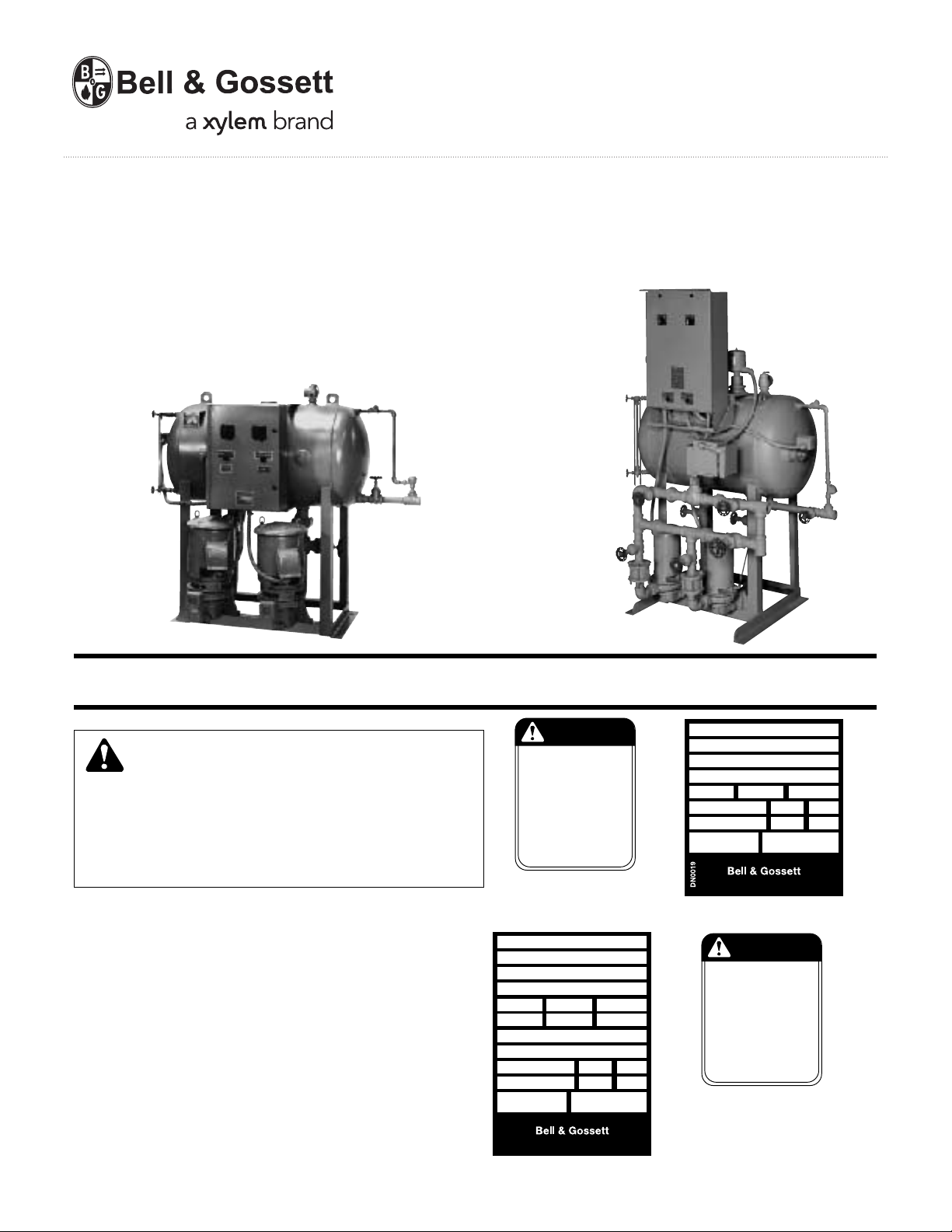
Domestic® Pump
250˚F Condensate Units
INSTRUCTION MANUAL
DN0130
REVISION D
Series SA™ and SA-P
™
SERIES SA-P
SERIES SA
™
INSTALLER: PLEASE LEAVE THIS MANUAL FOR THE OWNER’S USE.
WARNING
SAFETY
INSTRUCTIONS
This safety alert symbol will be used in this manual and on
the unit safety instruction decals to draw attention to safety
related instructions. When used, the safety alert symbol means
ATTENTION! BECOME ALERT! YOUR SAFETY IS INVOLVED!
FAILURE TO FOLLOW THESE INSTRUCTIONS MAY RESULT
IN A SAFETY HAZARD.
If the decals are missing or are illegible contact your local B&G
representative for a replacement.
1. Electrical connections to be made by a qualified Electrician
in accordance with all National, State and Local codes.
2. Motor must have properly sized starter with properly sized
heaters to provide overload and undervoltage protection.
3. If pump, motor or piping are operating at extremely high or
low temperatures, guarding or insulation is required.
4. Operating personnel should be trained in the operation of
condensate return units.
Ê
Ê
Ê
Ê
Ê
EXPLOSIBLE
DO NOT EXCEED PRESSURE
RATING OF THE UNIT.
DO NOT ALTER OR DEFEAT
PRESSURE RELIEF V
OPEN VALVES SLOWLY.
MAXIMUM PRESSURE 15 PSI.
FAILURE TO FOLLOW
INSTR
UCTIONS COULD
RESUL
T IN INJURY OR
PROPER
TY DAMAGE.
DN0124 ALL UNITS
Ê
Ê
Ê
Ê
Ê
Ê
Ê
Ê
Ê
SERIES
Ê
MODEL
Ê
SERIAL
GPM PSI PUMP
CFM IN HG. PUMP
Ê
DWGS
Ê
Ê
POWER V. PH. HZ60
CONTROL V. PH. 1 HZ60
TOTAL LARGEST MOTOR
F.L. AMP F.L. AMP
Morton Grove, Illinois 60053
DN0016
DN0016 UNITS PANEL
™
DOMESTIC® PUMPS
Ê
SERIES
Ê
MODEL
Ê
SERIAL
GPM PSI PUMP
POWER V. PH. HZ60
CONTROL V. PH. 1 HZ60
TOTAL LARGEST MOTOR
F.L. AMP F.L. AMP
Morton Grove, Illinois 60053
ALVE.
DN0124
DN0019 UNITS LESS PANEL
Ê
TM
Ê
TM
Ê
Ê
Ê
Ê
Ê
Ê
CAUTION
DO NOT RUN PUMP DRY,
SEAL DAMAGE MAY OCCUR.
INSPECT PUMP SEAL
REGULARL
REPLACE AS REQUIRED
FOR LUBRICATION
REQUIREMENTS,
SERVICE INSTR
FAILURE TO FOLLOW
INSTR
UCTIONS COULD
RESUL
T IN INJURY OR
PROPER
TY DAMAGE.
P70644 ALL UNITS
Ê
TM
Y FOR LEAKS,
CONSULT
UCTIONS.
Ê
Ê
Ê
Ê
Ê
.
P70644
Page 2
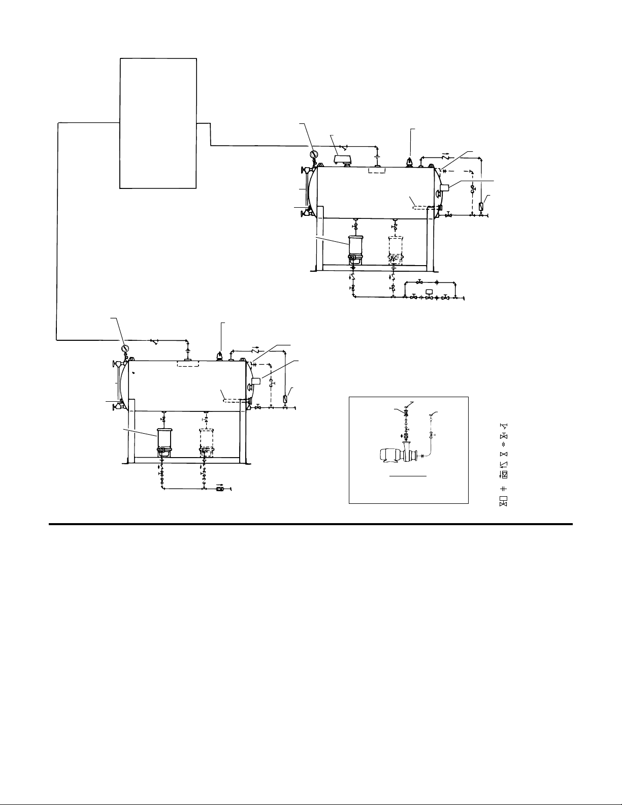
MECHANICAL DRAIN
VALVE (OPTIONAL)
FLOAT SWITCH
FOR STAND BY
THERMOSTATIC
VENT TRAP
TO DRAIN
PUMP
DISCHARGE
DOMESTIC SERIES B35
CENTRIFUGAL PUMP
(SERIES DB PUMP
OPT., SEE DETAIL AA)
GAUGE
GLASS
DIAL
TEMP.
GAUGE
ANODE
COMPOUND GAUGE
PROPORTIONING
REGULATOR
PRESSURE RELIEF VALVE,
PIPE TO DRAIN (PITCH DOWN)
STEAM
ABSORPTION UNIT
OR
CONVERTER
OR
FAN COIL UNIT
OR
STEAM PROCESS
EQUIPMENT
COMPOUND
GAUGE
GAUGE
GLASS
DIAL
TEMP.
GAUGE
DOMESTIC SERIES B35
CENTRIFUGAL PUMP
(SERIES DB PUMP
OPT., SEE DETAIL AA)
PUMP
DISCHARGE
TO DRAIN
ANODE
THERMOSTATIC
VENT TRAP
PRESSURE RELIEF VALVE
PIPE TO DRAIN (PITCH DOWN)
MECHANICAL DRAIN
VALVE (OPTIONAL)
FLOAT SWITCH
PUMP DISCHARGE
FLEXIBLE
PUMP
CONNECTOR
PUMP
SUCTION
LEGEND:
“Y” STRAINER
GATE VALVE
UNION
PLUG COCK
CHECK VALVE
NON SLAM
CHECK VALVE
FLANGE
PROPORTIONING
CONTROL VALVE
DETAIL AA
DETAIL OF RECOMMENDED PIPING TO
SERIES DB HIGH PRESSURE PUMP
1DPD22
1DPD32
High Temperature Condensate Units
Series SA and SA-P
REPRESENTATIVE PIPING DIAGRAMS
SERIES SA-P
DESCRIPTION OF EQUIPMENT
The Series SA, and SA-P units consists of an ASME Code
stamped steel receiver (permitting operating under pressure up
to 15 psig [1.0 Bar] and equivalent temperature up to 250°F
[121°C]). Series B35 centrifugal pump(s) designed for 2 ft. (0.6M)
NPSH, corrosion inhibitor (anode), water level gauge, thermometer, pressure relief valve, thermostatic air vent trap, compound gauge, valve(s) in pump suction, and a drain (gate)
valve. Occasionally, Series SA units are fully vented; these
receivers feature ASME Code construction except the code
stamped is omitted. In addition to the above components, the
Series SA-P employs a proportioning regulator and valve (electric or pneumatic). The Series SA unit uses float switch controls.
Control panels and components supplied per specification.
When Series SA units are furnished with ASME Code stamped
receivers, relief valve and air vent trap to permit pressurization,
then the receiver inlet is directly connected to the outlet of the
steam absorption unit or other steam process equipment with-
2
SERIES SA
out steam traps in the return line. When used in this manner, a
separate SA unit is usually required for each independently
controlled heating unit.
It is, however, possible to use a single SA unit with multiple
heating units. Detailed information and drawings will be furnished on request.
The relief valve on the unit is set at 15 psi (1.0 Bar) and rated at
1900 pph (862 Kg/hr) steam. Any additional system protection
must be provided as required by others.
PRELIMINARY INSPECTION
Assure that there is no shipping damage.
Assure that nameplate ratings agree with job specifications and
actual conditions.
HANDLING
Use care in installing unit.
Page 3
CAUTION: UNIT LIFTING EYE
Use unit lifting eyes only to lift unit as shipped from
factory. Unit must be empty and disconnected from pipes,
anchors and other restraints. Use proper rigging pr
ocedures. Failure to follow these instructions could result in
injury or property damage.
LOCATION
Place unit for easy access to all parts. Allow adequate space
for servicing. Check ambient conditions.
NOTICE / TEMPERATURE LIMITS
Motors are designed to operate in 104°F (40°C) max. ambient.
Insulate or ventilate as required.
WARNING: EXPLOSIBLE
Do not exceed pressure rating of unit (normally 15 psi
[1.0 Bar]). Do not alter or defeat relief valve (must be 15 psi
[1.0 Bar] max.). Pipe relief valve discharge to a safe location.
Failure to follow these instructions could result in serious
injury or death.
PIPING (General)
Pipe the unit per the Elementary Piping Diagram. Locate and
support piping so as to not load the pump discharge.
RETURNS
Gravity return lines from system should be properly pitched to
drain to unit by gravity. A “Y” strainer and gate valve should be
installed in the return line.
PIPING (Relief Valve)
The discharge from the relief valve should be piped to a location for safe for potential full flow steam. There must also be
provision for drainage of the liquid discharged.
WARNING: RELIEF VALVE REQUIRED
For sale operation the system requires a relief valve
set at 15 psi (1.0 Bar) or less. The relief valve discharge must
be piped to a location where 15 psi (1.0 Bar) steam can be
safely discharged. Do not restrict, reduce or valve the relief
valve discharge line. Failure to follow these instructions
could result in serious injury or death.
WARNING: LIMITED PRESSURE RELIEF
VALVE CAPACITY
The pressure relief valve supplied on the unit may not be
sufficient to relieve rated capacity of the unit or full output of
the boiler. Relief valve supplied is rated at 1900 pph (862
Kg/hr) steam. The tank is rated to withstand 125 psi (8.5 Bar),
but the operating pressure must not exceed 15 psi (1.0 Bar).
Professional system design or evaluation, by others, must
evaluate the upstream system and provide for necessary
additional protection. Discharge thru the pressure relief
valve is a symptom of a system failure. The unit must be
valved off immediately. Failure to follow these instructions
could result in serious injury, death or extensive property
damage.
THERMOSTATIC VENT TRAP OR ATMOSPHERIC VENT
Connect piping from drain line, thermostatic vent trap, and
mechanical drain valve (if so equipped) to drain. Occasionally,
Series SA units are furnished fully vented, without thermostatic
vent trap. Oversize vent openings are then supplied; install full
size vent pipe to atmosphere.
CAUTION: NOT A CHEMICAL PUMP
Inject boiler feed compounds from chemical feed tank
into boiler feed piping – never into condensate tank. Failure
to follow these instructions could result in injury or property
damage.
FLOAT SWITCHES & MECHANICAL ALTERNATORS
Float switch and/or displacer switches, standard or proportional,
are provided to meet system r
Floats are locked in place to prevent damage during ship
equirements.
ment.
Remove shipping locks. Check factory settings. Floats and
mechanical alternators are adjustable for various levels of operation. The lead pump should start with tank 3/4 full and shut of
at 2" (51mm) or more above pump inlet. Lag pump should start
before the tank overflows. Settings should avoid “short
cycling” of the pump.
Displacer positions are adjusted by removing the contr
oller
from the top of the tank and changing cable lengths.
PROPORTIONING ELECTRIC REGULATOR
AND PROPORTIONING (SLIDE WIRE) ELECTRIC VALVE
The regulator is actuated by a float-operated mechanism. Its
function is to regulate the action of the proportioning type of
motor operated valve, so the amount of flow through the valve
is in balance with the water level change.
By accurately following the changes in the water level, the float
actuates a potentiometer slide wire located in the proportioning
regulator. Connected to a similar potentiometer in a relay and
valve operator, the regulator causes the valve to open, close, or
hold in a fixed position.
PNEUMATIC PROPORTIONING
REGULATOR AND CONTROL VALVE
The pneumatic proportional control utilizes controlled air pressure to modulate the discharge valve opening. An air pressure
switch set a 2-3 psi (0.1-0.2 Bar) starts and stops the pump(s)
while the discharge valve is essentially closed.
DISCHARGE CONNECTION – SERIES SA AND SA-P UNITS
A check valve, gate valve and square head steam plug cock
should be located close to pump in discharge line. The plug
cock(s) may be omitted on Series SA-P units equipped with
proportioning discharge valves. If discharge line is more than
100 ft. (30M) long, it should usually be one size larger than the
pump tapping. When the pump is to discharge to a vented
receiver at approximately the same elevation, the steam pressure in the receiver may be greater than the static head at the
pump discharge causing condensate and steam to be forced
through the pump. This condition can be corrected by installing
a back-pressure valve with a spring pressure approximately
equal to the maximum receiver pressure.
ELECTRICAL WIRING & CONTROLS
Connect power wiring per NEC. Recheck nameplate vs. specifications and conditions. All single phase motors have internal
thermal protection.
WARNING: HIGH VOLTAGE ELECTRICITY
Disconnect and lock out power before connecting or
servicing unit. Failure to follow these instructions could
result in serious injury or death.
f
3
Page 4

Three phase motors must use starters with properly sized overload relays. Overload relays furnished are designed for manual
reset.
A variety of electrical controls are available to meet system
specifications. Wiring diagrams are enclosed in electrical
panels when the panels are furnished as part of the unit.
Consult wiring diagrams for specific electrical control
information.
INSULATION
Series SA units frequently handle condensate at temperatures
up to 250°F (121°C). Insulating the receiver and return piping
will effectively conserve heat otherwise lost through radiation
and convection from the receiver shell and reduce ambient
temperatures.
PUTTING THE UNIT INTO SERVICE
1. Assure that the unit is piped in accordance with instructions
on pages 2, 3 and 4.
WARNING: EXPLOSIBLE
Do not exceed 15 psi (1.0 Bar) rated pressure. Do not
restrict relief valve dischar
follow these instructions could result in serious injury or
death.
2. Check floats and alternators for fr
3. Check power leads in accordance with wiring diagram
enclosed in control cabinet (when furnished).
WARNING: HIGH VOLTAGE
Disconnect and lock out power before connecting or
servicing unit. Failure to follow these instructions could
result in serious injury or death.
4. Install drain plugs.
5. Fill receiver half full of water to prime pump(s) and prevent
possible damage to pump seals. Avoid freezing conditions
after unit receiver has been filled.
6. Check for proper rotation of all three phase motors. Rotation
must be clockwise looking down on the motor as indicated
by directional arrow on pump casting. If pump runs backwards, interchange two wires (3 phase only).
ge. Open valves slowly. Failure to
ee operation.
CAUTION: DO NOT REVERSE
Reverse operation can cause extensive damage to
pumps. Jog the motor to test for direction of rotation. Failure
to follow these instructions could result in injury or property
damage.
7. Throttle plug cock in discharge line until pressure at pump
(while pump is discharging) approaches pump rated pr
sure. Tighten plug nut to secure adjustment.
CAUTION: DO NOT RUN DRY
SEAL DAMAGE MAY OCCUR.
Inspect pump seal regularly for leaks. Replace as required.
Failure to follow these instructions could result in injury or
property damage.
8. Remove start-up label (below) from panel (if applicable) after
complying with instructions.
ELECTRICIAN / INSTALLER / OPERATOR
Remove and destroy this tag after –
1.Assuring that all pumps rotate clockwise per arrows cast
on volutes. (Jog pump momentarily to test – interchange
any two motor power wires to reverse 3Hp motors.)
2.Assuring that shipping locks have been removed from all
float switches.
9. If possible, observe operation thru several cycles.
.
es-
OPERATION AND MAINTENANCE
Operators must be familiar with all sections of this manual to
understand the operation of the unit.
Hot water, steam and electricity can be hazardous.
SAFETY INSTRUCTIONS
SEE COVER OF THIS MANUAL
WARNING: EXPLOSIBLE
Do not exceed 15 psi (1.0 Bar) rated pressure. Do not
restrict relief valve discharge. Open valves slowly. Failure to
follow these instructions could result in serious injury or
death.
WARNING: HIGH VOLTAGE
Disconnect and lock out power before connecting or
servicing unit. Failure to follow these instructions could
result in serious injury or death.
Check motor nameplate for any lubrication requirements.
Pumps require no lubrication.
4
NOTICE / AUTO RESTART
Single phase motors will restart automatically after
thermal overload protector trips.
Overload thermal relays in starters must be reset manually.
A properly installed unit should function unattended for long
periods of time. Periodic checks to assure proper operations
are highly recommended. Refer to trouble shooting section
when necessary.
A variety of control options are available and are furnished in
accordance with user specifications. Refer to wiring diagrams
(when furnished) to determine control switch settings.
The inlet strainer (when furnished) is intended to protect the
pump and system. Periodic cleaning should be included in the
maintenance schedule. Check frequently in new systems.
CAUTION: SUBSEQUENT DAMAGE
A unit showing symptoms of possible problems (overflow, noise, leaks, vibrations, continual operation, etc.) must
be corrected immediately. Failure to follow these instructions may result in full liability for subsequent injury or property damage.
Page 5

MAINTENANCE PROCEDURE FOR RED LINE GAGE GLASS
PYREX® Tubular Glass
Nut
Insure Clearance Between
Glass Surface and the
Upper and Lower Fixtures
Tie Rod
Gland
Packing
WARNING: EXPLOSIBLE
Improper installation or maintenance of tubular glass
can cause immediate or delayed glass breakage resulting in
bodily injury. To avoid br
eakage observe the following Do’s
and Do Not’s and Use and Care Instructions, as well as
tubular gage manufacturer’s instructions. If a gage glass
breaks, contained substances can be released and glass
can be blown out of the unit with great force. Always wear
safety glasses when looking toward a gage or working on a
gage glass assembly. Guard against the possibility of fir
e
and explosion. Protect glass from impact, scratches, other
surface damage and sudden temperature changes. These
can weaken or stress the glass and lead to breakage.
Failure to observe the following Do’s and Do Not’s can result
in glass breakage and its explosive release of pressurized
system contents and flying glass particles.
DO NOT’S
DO NOT work on any gage until you have carefully read these
warnings & instructions.
DO NOT reuse any tubular glass, packing, or seals.
DO NOT use glass that is scratched, chipped, or otherwise
damaged. Used glasses may contain damage and are poor
safety risks.
DO NOT exceed the glass or gage manufacturer’s recommended working pressure or maximum recommended gage
glass length.
DO NOT bump, impact or scratch the glass.
DO NOT tighten gland nut and packing beyond gage manufac-
turer’s recommendations.
DO NOT operate gages unless gage valve sets are equipped
with drain vent and safety ball check.
DO NOT attempt to clean glass while the unit is in operation.
Cleaning should be done without removing the gage glass.
DO NOT attempt to inspect the glass, to adjust tie rods, pack-
ing nuts or glands, to inspect or tighten other fittings without
isolating the gage from the pressure vessel and opening the
drain vent.
DO NOT weld, impact, or sandblast in the gage glass area
without protecting the glass.
DO NOT have glass-to-metal contact.
DO NOT subject gage glass to bending or twisting stresses.
DO NOT allow the gage glass to contact the bottom of the
packing gland.
DO’s
DO inspect the gage glass daily, keep maintenance records,
and conduct routine replacements.
DO install protective guards where necessary to protect
personnel.
DO protect the outside of the gage glass from sudden temper
ature changes, such as drafts, water spray, etc.
DO remove all deposits from the seal areas, the gland nuts,
glands (where used) and use new packing before installing a
tubular gage glass.
DO examine gage glass for damage and seals for hard deposits
and tears.
DO verify that the tubular gage glass, gland, nuts, packing, etc.
are the correct size and type before installing.
DO ensure that system is protected by safety shut-off system
(e.g. safety ball check).
MAINTENANCE
Examine the gage glass regularly for any signs of clouding,
scratching, erosion, or corrosion. In new processes, the glass
should be inspected daily until the need for replacement
becomes apparent. This will help establish the routine inspection and routine replacement cycles.
CLEANING
Keep gage glass clean using non-abrasive commercial glass
cleaners. Where regular cleaners do not seem to work, use
dilute acids such as Hydrochloric (muriatic) acid. Always
observe safety rules when handling hazardous cleaning solutions. Never use wire brushes, metal scrapers, or harsh abrasives which could scratch the glass.
INSPECTION
Scratches, corrosion, chips, surface flaws, or nicks on the surface or edges weaken the gage glass. To examine for these,
shine a very bright concentrated light (“Burton Lite” or powerful flashlight) at about 45° angle. Anything which glistens and
catches the fingernail or any star-shaped or crescent-shaped
mark which glistens, is cause for replacement. Any gage glass
which appears cloudy or roughened and will not respond to
cleaning procedures, should be replaced.
STORING
Keep gage glasses in original packaging until ready to install.
HANDLING
Avoid bumping, chipping, or scratching glass. Any glass-toglass contact can cause scratches and must be avoided.
-
INSTALLATION
Always follow tubular gage manufacturer’s recommended procedures for glass replacement.
Before installing a gage glass, remove all deposits from the seal
contact surfaces of the gland nut and the gland (where used).
Check sealing surfaces for cleanliness and smoothness. Once
a gage glass has been removed from its mounting, regardless
of the reason for its removal. Discard the glass and replace with
a new piece.
Always use new packing, seals, and/or O-rings (if required)
when replacing a tubular gage glass. Used packing seals and
O-rings will not properly support the gage glass or provide the
proper pressure seal without stressing the glass.
5
Page 6

1. Hold fittings rigidly to prevent misalignment, which can
cause severe bending stresses in the glass, when packing
nuts are tightened.
2. Provide metal washers so nuts can be tightened without
twisting packing or tube.
3. Provide positive, but not excessive, clearance between
glass, packing nuts, and bearing washers.
4. Keep glass short enough to allow for expansion.
5. Provide positive clearance between the ends of the gage
glass and the metal fittings. Glass-to-metal contact will
keep the gage glass from expanding and cause breakage.
6. Tighten packing nuts enough to prevent leakage, but not so
much that you hinder expansion and contraction. Follow
gage manufacturer’s r
7. Generally, you can use cylindrical or conical rubber pack
ings for LOW and MEDIUM pressures. HIGHer pressures
and HIGH temperatures may require specialized packings.
In all cases you should follow the recommendations of the
gage manufacturer.
ecommendations.
-
TROUBLE SHOOTING PROCEDURES
All units are thoroughly tested at the factory before shipment.
They should operate satisfactorily without further adjustment if
properly installed and providing they have not been damaged
by rough handling in transit. If system or unit performance is
not satisfactory, refer to the following check list.
Pump Will Not Start
1. The power supply has been interrupted, disconnect switch
is open, or selector switch is improperly positioned.
2. Incorr
3. Incorr
4. The overload r
5. Check pump contr
6. Wiring to control cabinet is incorrect or connections are
7. The strainer is dirty thus retarding flow. Clean periodically.
Pump Runs Continuously
1. Pump is running backward. Rotation of three phase motors
2. The total required pressure at the pump discharge is greater
3. A valve in the discharge line is closed or throttled too
4. The impeller eye is clogged.
5. Pump is too small for system.
Condensate Pump is Noisy
1. The pump is working against a lower pressure than
ect voltage for motor. Check voltage and wiring with
motor characteristics.
ect starter coil for power supply.
reset. Ambient temperatur
loose.
may be corrected by interchanging any two of the three
wires. Rotation should be clockwise looking down on motor.
than the pressure for which the pump was designed. Check
the total pressure which includes atmospheric pressure, the
friction head and the static head.
tightly. Check valve is installed backwards.
designed for. While pump is discharging, adjust plug cock in
discharge line until pressure at pump approaches pump
rated pressure.
elays the starter have tripped out and must be
e may be too high.
ols or other controls for proper operation.
2. Excessive condensate temperature. Correct system conditions. However, this applies to certain units only; others are
designed to handle boiling water.
3. Magnetic hum or bearing noise in motor. Consult motor
manufacturer’s authorized service station nearest unit
location.
4. Starter chatters. Trouble is caused by low line voltage, poor
connections, defective starter coil, or burned contacts.
5. Pump is running backwar
The System is Noisy
1. Banging in the steam main is usually caused by steam
“imploding” in condensate lying in low points in lines. These
problems can be eliminated by dripping low points, pr
supporting the pipe, or by increasing the pitch of the lines.
2. Impr
3. The piping is too small to drain properly.
Steam Flow is Restricted
1. Thermostatic vent not open when cold.
2. Valve closed between vent line and drain or checkvalve
Relief Valve Discharging
1. Incoming steam pressure exceeds 15 psi (1.0 Bar) –
SA-P Pumps Don't Start or Run Continuously
1. If pneumatic system, check pressure setting or pneumatic
2. If electric, check displacer adjustments.
oper dripping of the steam mains and risers; where
there is a rise in the steam main, or where it branches off into
a riser, a drip trap must be installed in the drain line.
installed backwards.
upstream pressure must not exceed 15 psi (1.0 Bar). Correct
system.
pressure switch. Air pressure to engage switch at 2-3 psi
(0.1-0.2 Bar).
d.
operly
6
Page 7

7
DEALER SERVICING
If trouble occurs that cannot be rectified, contact your local
B&G r
epresentative. He will need the following information in
order to give you assistance.
1. Complete nameplate data of pump and motor. SEE RATING
NAMEPLATE.
2. Suction and discharge pipe pressure gauge readings.
3. Ampere draw of the motor.
4. A sketch of the pump hook-up and piping.
1. Close pump isolation valve or system return line valve.
Operate pump momentarily to discharge as much water as
possible. Close pump discharge valve.
2. Shut-off and lock out power.
3. Make sure unit is cool enough that pump can be handled
safely. Open drain to remove remaining liquid.
4. Carefully remove pump drain plug and bleed line. Wait for
complete drainage.
5. Loosen both the discharge connection and the suction
housing to pump volute fasteners. Assure that pressure is
relieved per caution note.
6. Complete the removal of the above hardware. Remove
pump/motor assembly and place on work bench.
7a. Remove the suction housing capscrews and separate the
pump/motor assembly from the suction housing. Note, the
diffuser should separate from the suction housing to allow
the pump/motor assembly to be removed.
7b. Remove propeller, propeller stem and diffuser from the
assembly as follows:
(1) Threaded Motor Shafts (3Hp and less). Remove pro-
peller lock nut. Remove propeller with propeller stem as
an assembly with the diffuser. To install a new propeller,
remove the propeller set screws and separate from the
stem.
(2) Keyed Motor Shafts (5Hp and larger). Remove propeller
set screws. Remove propeller, remove diffuser, and
unscrew the propeller stem.
Morton Grove, Illinois 60053
TM
TM
SERIES
MODEL
SERIAL
GPM PSI PUMP
CFM IN HG. PUMP
DWGS
POWER V. PH. HZ60
CONTROL V. PH. 1 HZ60
TOTAL LARGEST MOTOR
F.L. AMP F.L. AMP
DN0016
PUMP SERVICE INSTRUCTIONS FOR SERIES B35 PUMPS AS USED ON SA & SA-P UNITS
CAUTION: PRESSURIZED SYSTEM
Operating system may contain very hot water and
steam under pressure. Close inlet and open drains before
servicing. When servicing, loosen screws and move components to assure pressure is relieved before removing screws.
Keep drains open during servicing. Failure to follow these
instructions could result in injury or property damage.
CAUTION: HOT SURFACES
Surfaces are hot when system is in operation. Do not
touch hot receiver, let unit cool before servicing. Failure to
follow these instructions could result in serious injury or
death.
WARNING: HIGH VOLTAGE
Disconnect and lock out power before connecting or
servicing unit. Failure to follow these instructions could
result in serious injury or death.
HEAVY DUTY
BALL BEARING MOTOR
WATER SLINGER
MECHANICAL SEAL
STAINLESS STEEL SHAFT
MOTOR BRACKET
PUMP VOLUTE W/WEAR RING
IMPELLER
IMPELLER
AXIAL FLOW PROPELLER
PROPELLER SET SCREW
SUCTION HOUSING
Page 8

Xylem Inc.
8200 N. Austin Avenue
Morton Grove, Illinois 60053
Phone: (847) 966-3700
Fax: (847) 965-8379
www.xyleminc.com/brands/bellgossett
Bell & Gossett is a trademark of Xylem Inc. or one of its subsidiaries.
© 2012 Xylem Inc. DN0130D November 2012
 Loading...